Jetson Device Tree
In the previous two articles, we walked through the complete boot process of a Jetson from power-on to Ubuntu using the UART boot log:
Power On --> MB1/2 --> UEFI --> L4TLauncher --> Linux Kernel --> RootFS --> Systemd
Once you understand the boot chain, the next natural question is: How does Linux actually know which hardware is connected on this board?
For example, the same Jetson Orin Nano Module works fine on the official NVIDIA Developer Kit Carrier Board, but when you move it to another Carrier Board, USB may stop working.
The Jetson module hasn't changed, and the Linux Kernel hasn't changed either. So why can simply swapping the carrier board completely change the behavior of the whole system? This brings us to a very important concept in Jetson hardware development: Device Tree. In this article, we will mainly address the following questions:
- What exactly is the Device Tree that people keep talking about?
- Why can't many hardware components be used directly after changing the Carrier Board?
- Why do Seeed Studio Jetson carrier boards need their own BSP, instead of directly using the NVIDIA official BSP?
What Exactly Is Device Tree?
As mentioned earlier, the Linux Kernel is responsible for managing the low-level hardware in the system. So how does the Kernel know what devices are on the carrier board? The answer is Device Tree. The role of Device Tree is to tell the Linux Kernel what hardware is on the board and how that hardware is connected. For example, the schematic defines that a sensor is connected to a certain I2C bus, what the bus address is, and which GPIO the Reset is connected to; this kind of information usually appears in the Device Tree in the corresponding form. So I prefer to think of the Device Tree as a hardware connection manual written for the Linux Kernel.
Schematics are drawn for humans; the Device Tree is written for the Linux Kernel.
Later, we will combine this with Seeed Studio's real L4T BSP to see what these "hardware connection relationships" actually look like in code. Seeed Studio has open-sourced the BSP of all Jetson products in Seeed-Studio/Linux_for_Tegra. There are many files ending in .dts in the repository — these are the Device Tree files we are going to discuss.
An Example: How Does Device Tree Affect PCIe / NVMe?
We said Device Tree is "a hardware connection manual written for the Linux Kernel". So what does it actually look like in real code? Let's look directly at the Device Tree of the Seeed Studio J401. In the Seeed Studio open-source repository, there is a Device Tree file named tegra234-j401-p3768-0000+p3767-0000.dts. Opening it, you can see a node like this:
vdd_3v3_pcie: regulator-vdd-3v3-pcie {
    compatible = "regulator-fixed";
    regulator-name = "VDD_3V3_PCIE";

    regulator-min-microvolt = <3300000>;
    regulator-max-microvolt = <3300000>;

    gpio = <&gpio_aon
            TEGRA234_AON_GPIO(AA, 5)
            GPIO_ACTIVE_HIGH>;

    enable-active-high;
};
This configuration describes a 3.3V power rail used for PCIe. Some of the more important information here is:
regulator-name
→ This power rail is named VDD_3V3_PCIE

3300000
→ The voltage is 3.3V

TEGRA234_AON_GPIO(AA, 5)
→ Controlled by AON GPIO AA.5

enable-active-high
→ This power rail is enabled when the GPIO is driven high
In other words, a certain PCIe Power Enable signal on the Carrier Board schematic is ultimately described to Linux through the Device Tree. This is a very intuitive example of "hardware connection relationships being written into the Device Tree". When all these configurations are correct, the Kernel has the chance to establish the PCIe Link and detect the NVMe connected to the PCIe bus. Let's combine this with the boot log from the previous article. When the configuration is correct, the UART boot log shows something like:
[    6.639293] tegra194-pcie 14160000.pcie: Link up
[    6.649851] nvme nvme0: pci function 0004:01:00.0
[    6.665906] nvme0n1: p1 p2 p3 ...
So we can build a very important relationship here:
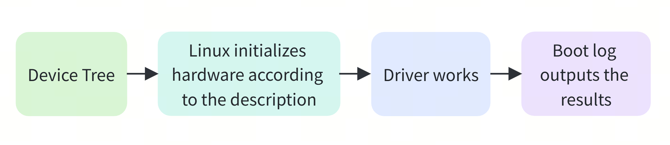
In other words, the boot log shows the result, while the Device Tree is one of the important configuration sources that produce that result.
If the Device Tree does not match the real Carrier Board, problems will occur. Suppose the new Carrier Board moved the PCIe 3.3V Enable to a different GPIO, but the Device Tree still says:
AON GPIO AA.5
Then Linux may keep controlling the wrong GPIO according to the old design.
As a result, the NVMe SSD may not be detected properly: the boot log may reach the Linux Kernel, but the PCIe Link up message never appears. By now, you should have a basic understanding of the Device Tree.
Device Tree File Formats: What's the Difference Between DTS, DTSI, DTB, and DTBO?
In the Jetson BSP, you often see these four types of files: .dts, .dtsi, .dtb, and .dtbo. They look very similar, but their roles are different.
| File | Full Name | Main Role | Directly Readable | Example in Seeed Open-Source Repo |
|---|---|---|---|---|
| .dts | Device Tree Source | Describes a specific board or an overlay | ✅ | tegra234-j401-p3768-0000+p3767-0000.dts |
| .dtsi | Device Tree Source Include | Stores common configurations reusable by multiple DTS files | ✅ | tegra234-p3768-0000+p3767-xxxx-nv-common.dtsi |
| .dtb | Device Tree Blob | Binary Device Tree compiled from DTS/DTSI | ❌ | tegra234-j401-p3768-0000+p3767-0000-recomputer.dtb |
| .dtbo | Device Tree Blob Overlay | Adds or modifies part of the hardware configuration on top of the base Device Tree | ❌ | tegra234-p3767-camera-p3768-imx219-dual-seeed.dtbo |
First, Let's Look at DTS and DTSI
You can think of .dts as the "entry file" of a specific board, while .dtsi is more like a common configuration module.
For example, the DTS of the Seeed J401 includes other Device Tree files:
#include "tegra234-p3767.dtsi"
#include "tegra234-p3768-0000.dtsi"
So in a real project, the Device Tree is not one huge .dts file written all the way through; it is composed of many .dtsi files combined layer by layer.
You can compare it to the C language:
.dtsi is somewhat like .h
.dts is somewhat like the .c that finally combines these configurations
Of course, this analogy is not exactly equivalent; it is just to help you understand the relationship between them more quickly.
DTB: The Binary Device Tree Linux Actually Uses
.dts and .dtsi are meant for developers to read and modify.
After they are compiled by dtc (Device Tree Compiler), .dtb files are generated.
What Linux actually reads at boot is the compiled .dtb, not the .dts files in the source directory.
DTBO: Modifying Only Part of the Hardware Configuration
Some hardware is not installed on every device, for example cameras. If you had to copy and maintain the entire J401 Device Tree just to add one IMX219 sensor, it would be very cumbersome. This kind of problem can be handled with a DTBO (Device Tree Overlay).
For example, there is a Camera Overlay in the Seeed BSP:
tegra234-p3767-camera-p3768-imx219-dual-seeed.dtbo
It is not a complete J401 Device Tree; it only describes the IMX219 Camera related configuration, such as:
- I2C address
- Reset / Power GPIO
- CSI interface
- NVCSI / VI connection relationships
- Camera Sensor node
- etc.
You can also see similar configuration in Seeed's recomputer-orin-j401.conf:
OVERLAY_DTB_FILE+=tegra234-p3767-camera-p3768-imx219-dual-seeed.dtbo
In other words, the base hardware configuration of the J401 still uses the original DTB; you only need to additionally add the Camera-related configuration.
Beyond Device Tree: Jetson Also Has Earlier Board-Level Configuration
At this point, I believe you have a general understanding of the Device Tree, and you already have the answer to the question at the beginning of this article. But have you noticed a new question:
The Device Tree is the schematic for the Linux Kernel. But based on the boot log from the previous article — before the Linux Kernel even starts, who configures the GPIO, Pinmux, and Pad Voltage? The answer is: the Bootloader stage itself also has its own set of board-level configuration.
So on Jetson, you cannot simply equate "carrier board adaptation" with "modifying a Kernel DTB". A more complete relationship should be:
                Carrier Board
                     ↓
              Real hardware connections
                     ↓
        ┌────────────┴────────────┐
        ↓                         ↓
Bootloader Board Config     Kernel Device Tree
        ↓                         ↓
   MB1 / MB2 / UEFI          Linux Kernel
        ↓                         ↓
Pinmux / Pad Voltage        USB / PCIe / Camera
 GPIO / Early HW             Ethernet / Sensor
If you want to understand the relationship between them, I suggest you learn directly from Seeed Studio's Linux_for_Tegra repository.
Taking the J401 as an example, recomputer-orin-j401.conf is used when flashing. You can think of this file as an important "board-level configuration entry" for the J401.
Depending on the Jetson Module SKU, it selects the corresponding DTB, for example:
tegra234-j401-p3768-0000+p3767-0000-recomputer.dtb
tegra234-j401-p3768-0000+p3767-0001-recomputer.dtb
tegra234-j401-p3768-0000+p3767-0003-recomputer.dtb
tegra234-j401-p3768-0000+p3767-0004-recomputer.dtb
Here you can see a very important piece of information:
Device Tree is not only related to the Carrier Board; it is also related to the combination of Carrier Board + Jetson Module.
But the .conf file contains more than just:
DTB_FILE --> The Kernel Device Tree used by Linux
You will also see:
PINMUX_CONFIG --> Pinmux configuration
PMC_CONFIG --> Pad Voltage / PMC related configuration
OVERLAY_DTB_FILE --> Additional overlays such as Camera and Display
BPFDTB_FILE --> Device Tree used by BPMP
We will not go into the details of the rest here. If you are interested, you can study it on your own, and you are also welcome to join the Seeed Jetson community to discuss it together.
How to Confirm the Device Tree Linux Is Currently Actually Using?
If the device can already boot into the system desktop, you can also directly check the Device Tree the current system is actually running.
Export the currently running Device Tree:
sudo dtc -I fs -O dts /proc/device-tree > running.dts
Then you can directly inspect the corresponding nodes. For example:
grep -n "pcie" running.dts
grep -n "usb" running.dts
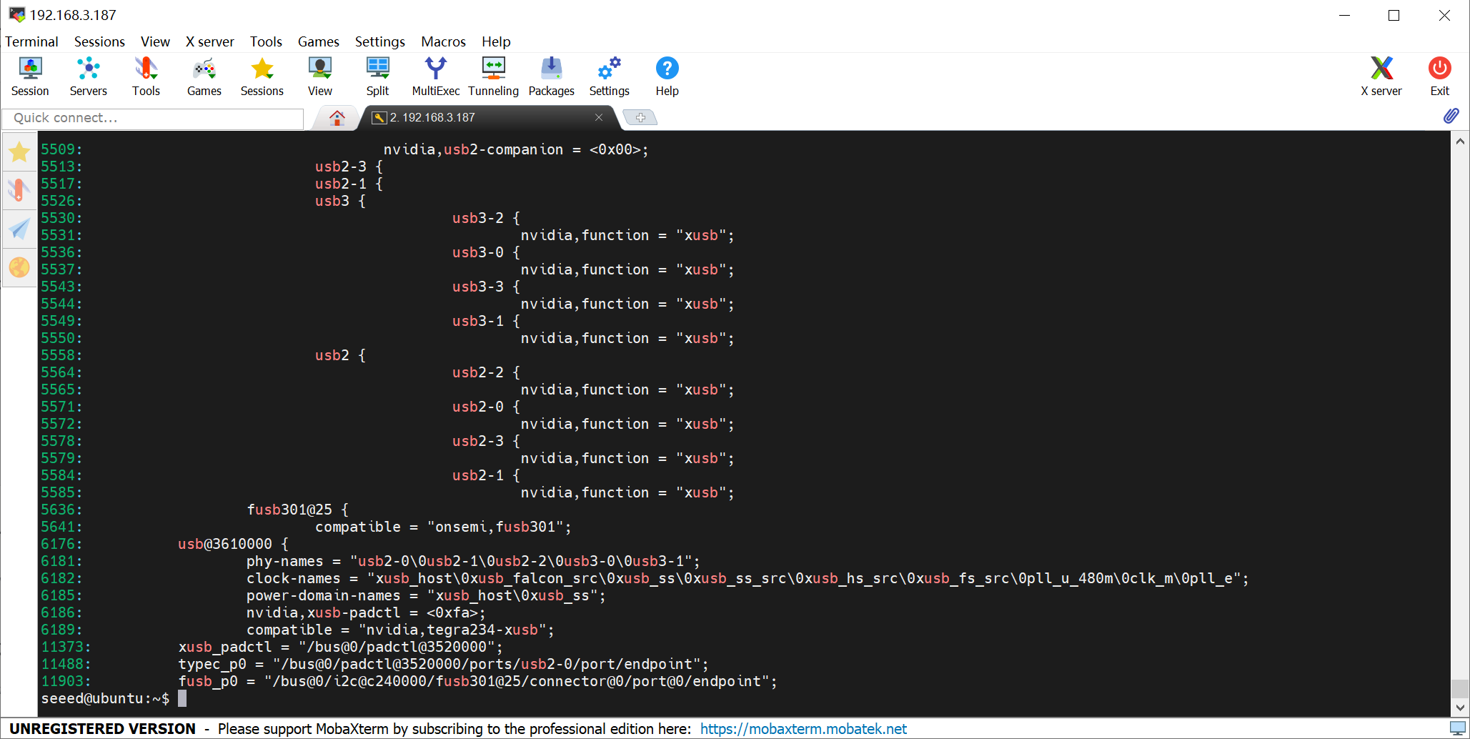
When debugging the Device Tree, what you should really confirm is not only which DTS you modified, but more importantly whether the system is actually loading the modified version.
Conclusion
The Device Tree itself is not complicated. The core problem it solves is actually only one:
Let the software know what hardware is on this Carrier Board and how that hardware is connected.
But on Jetson, carrier board adaptation is not just the Kernel Device Tree.
From Seeed Studio's L4T BSP, you can see that what a carrier board really needs is a complete set of board-level configurations. This is also why Seeed Studio's Jetson products need their own BSP, instead of simply directly using the NVIDIA Developer Kit configuration.
Tech Support & Product Discussion
Thank you for choosing our products! We are here to provide you with different support to ensure that your experience with our products is as smooth as possible. We offer several communication channels to cater to different preferences and needs.