Use an SPI Display on reComputer J4012 Classic
Introduction
This wiki introduces how to connect and drive an SPI display on the Seeed reComputer J4012 Classic. It covers the basic workflow of using an SPI display through the 40-pin header, including hardware wiring, SPI interface configuration, device node checking, dependency installation, compiling a C++ demo, and running a simple display test.
In this guide, an ST7789 SPI LCD display is used as an example. For other SPI display modules, such as ST7735 or ILI9341, the overall workflow is similar, but the wiring details, display resolution, initialization sequence, and driver parameters may be different.
The method in this guide can also be used as a reference for other SPI display applications.
Hardware Preparation
Required Hardware
| Item | Description |
|---|---|
| reComputer J4012 Classic | Jetson-based edge AI computer |
| SPI display module | This guide uses an ST7789 SPI LCD display as an example |
| Dupont wires | Used to connect the display to the 40-pin header |
| HDMI display or SSH terminal | Used to configure and test the device |
Required Software
| Software | Description |
|---|---|
| JetPack / Ubuntu | Operating system running on reComputer J4012 Classic |
| g++ | Used to compile the C++ demo |
| spidev | Linux SPI userspace interface |
| sysfs GPIO | Used to control GPIO pins such as DC and RES |
Hardware Connection
40-pin Header
The reComputer J4012 Classic provides a 40-pin expansion header. SPI signals and GPIO pins can be used through this header to connect small display modules.
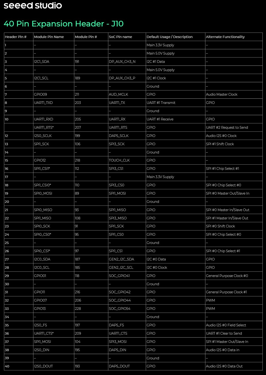
Figure 1. 40-pin header pinout of reComputer J4012 Classic
SPI Display Wiring Example: ST7789
In this guide, an ST7789 SPI display is used as the example display module. Connect the display to the 40-pin header according to the table below.
| ST7789 Pin | J4012 Classic 40-pin Pin | Function | Description |
|---|---|---|---|
| GND | Pin 6 | GND | Ground |
| VCC | Pin 1 | 3.3V | Power input for the display |
| SCL | Pin 23 | SPI SCLK | SPI clock signal |
| SDA | Pin 19 | SPI MOSI | SPI data from J4012 Classic to the display |
| RES | Pin 31 | GPIO / PQ.06 | Hardware reset signal |
| DC | Pin 29 | GPIO / PQ.05 | Data / command selection |
| CS | Pin 24 | SPI CS | SPI chip select |
| BLK | Pin 17 | 3.3V | Backlight power, always on |
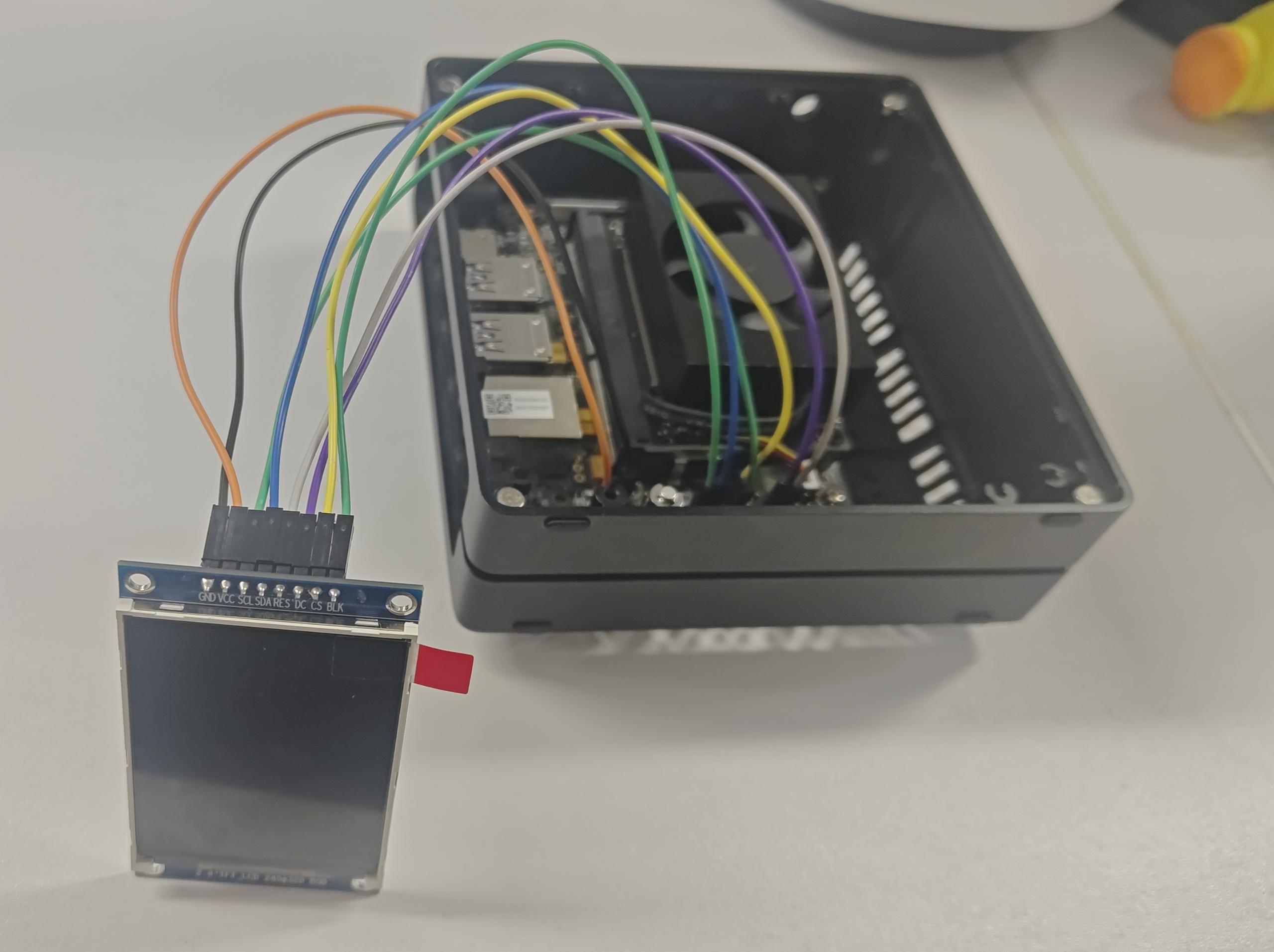
Figure 2. Wiring between reComputer J4012 Classic and ST7789 SPI display
Enable SPI Interface
- JetPack 5 / JetPack 6
- JetPack 7
Before running the display demo, the SPI interface on the 40-pin header should be enabled.
Open the Jetson-IO configuration tool:
sudo /opt/nvidia/jetson-io/jetson-io.py
Select the 40-pin header configuration menu.
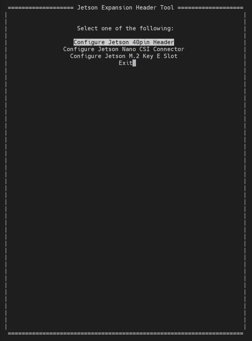
Figure 3. Jetson-IO main menu
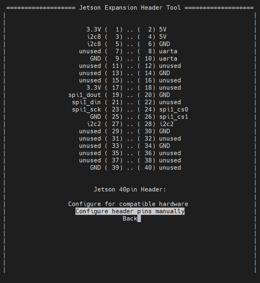
Figure 4. Select "Configure header pins manually"
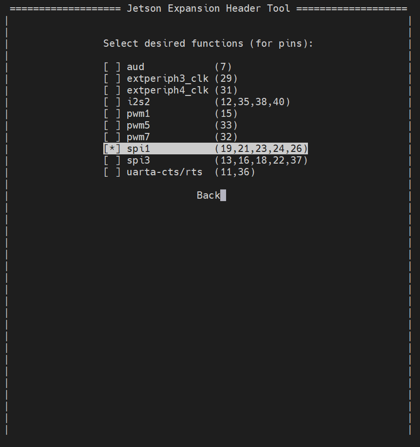
Figure 5. Enable spi1 function on the 40-pin header
Save the configuration and reboot the device:
sudo reboot
After the device reboots, load the spidev kernel module:
sudo modprobe spidev
This step makes sure the Linux userspace SPI driver is available before checking or accessing /dev/spidev*.
Before running the display demo, enable the SPI interface and configure the GPIO pins used by the display in the Jetson Expansion Header Tool.
Open the Jetson-IO configuration tool:
sudo /opt/nvidia/jetson-io/jetson-io.py
Select the 40-pin header configuration menu.
Figure 3. Jetson-IO main menu
Figure 4. Select "Configure header pins manually"
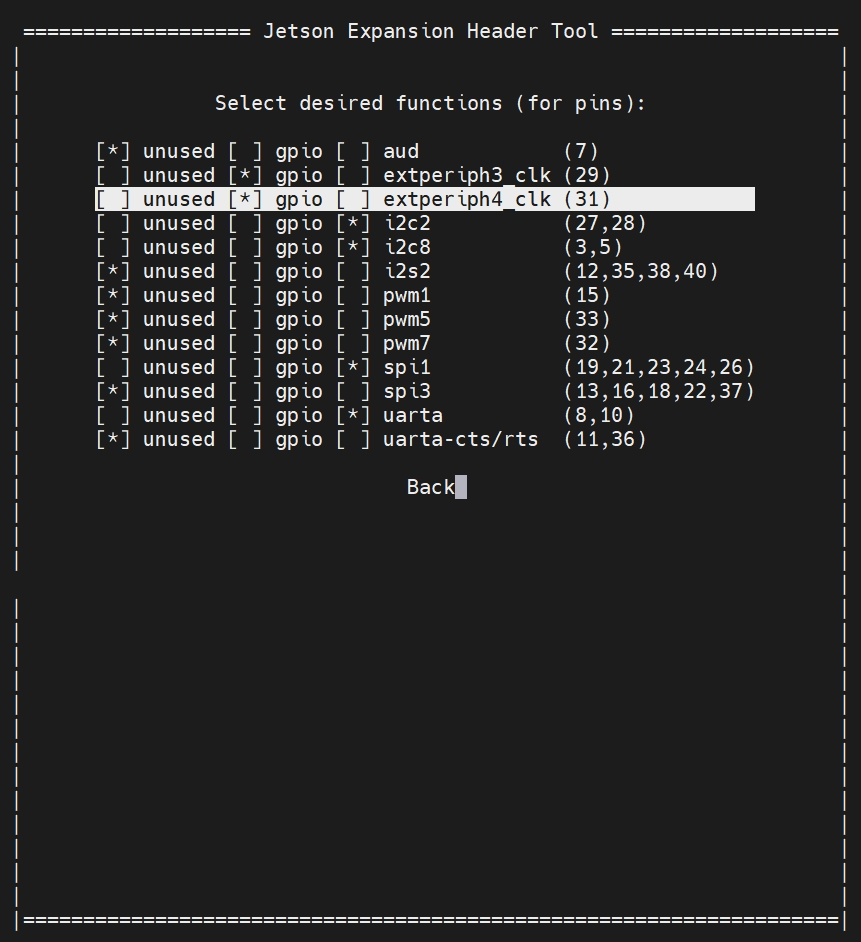
Figure 5. Enable spi1 and configure Pin 29 and Pin 31 as gpio
In JetPack 7, select the following functions in the Jetson Expansion Header Tool:
- Enable
spi1for the SPI signals on Pin 19, Pin 23, and Pin 24. - Set Pin 29 (
extperiph3_clk) togpiofor theDCsignal. - Set Pin 31 (
extperiph4_clk) togpiofor theRESsignal.
Save the configuration and reboot the device:
sudo reboot
After the device reboots, load the spidev kernel module:
sudo modprobe spidev
This step makes sure the Linux userspace SPI driver is available before checking or accessing /dev/spidev*.
Check SPI Device
After the device reboots, check whether the SPI device node has been generated:
ls /dev/spidev*
If SPI is enabled correctly, you may see output similar to the following:
/dev/spidev0.0
/dev/spidev0.1
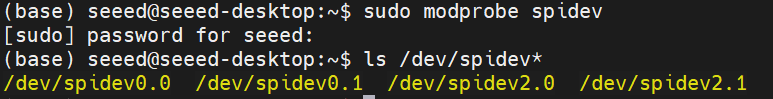
Figure 6. SPI device node generated successfully
In this guide, the ST7789 display uses the SPI signals connected to Pin 19, Pin 23, and Pin 24. The example code uses /dev/spidev0.0 by default. If your system generates a different SPI device node, please modify the SPI device path in the code.
Install Dependencies
Update the package list:
sudo apt update
Install the C++ compiler:
sudo apt install -y g++
Check whether the SPI device node exists:
ls /dev/spidev*
GPIO Control
- JetPack 5
- JetPack 6
- JetPack 7
Before running the display demo, export the GPIO pins used by DC and RES. The demo controls these two pins through the sysfs GPIO interface.
In this guide:
| Signal | 40-pin Pin | GPIO name | GPIO number |
|---|---|---|---|
| DC | Pin 29 | PQ.05 | 453 |
| RES | Pin 31 | PQ.06 | 454 |
When exporting GPIO through /sys/class/gpio/export, use the GPIO number instead of the GPIO name. In this guide, GPIO 453 corresponds to PQ.05, and GPIO 454 corresponds to PQ.06:
sudo sh -c 'echo 453 > /sys/class/gpio/export'
sudo sh -c 'echo 454 > /sys/class/gpio/export'
After exporting, the corresponding GPIO nodes should appear as PQ.05 and PQ.06. Check whether the GPIO nodes exist:
ls /sys/class/gpio/PQ.05
ls /sys/class/gpio/PQ.06
JetPack 6 uses the Linux character device GPIO interface. The DC and RES pins are controlled through libgpiod, so no sysfs GPIO export step is required. However, on JetPack 6 the GPIO pins must first be configured through the pinmux registers before they can be used as GPIO outputs.
The GPIO names for these signals are:
| Signal | 40-pin Pin | GPIO name |
|---|---|---|
| DC | Pin 29 | PQ.05 |
| RES | Pin 31 | PQ.06 |
Configure GPIO Pinmux
Before using libgpiod, configure the DC and RES pins as GPIO outputs through the pinmux registers.
Install busybox:
sudo apt install -y busybox
Use jetson-gpio-pinmux-lookup to find the pinmux register address for each 40-pin header pin:
jetson-gpio-pinmux-lookup 29
jetson-gpio-pinmux-lookup 31
The tool prints the register address for each pin. Write 0x004 to that address to set the pin as a GPIO output.
For example, to configure Pin 31 (RES / PQ.06) as a GPIO output:
sudo busybox devmem 0x02430070 w 0x004
Similarly, configure Pin 29 (DC / PQ.05) using the address returned by jetson-gpio-pinmux-lookup 29:
sudo busybox devmem <ADDRESS_FROM_LOOKUP> w 0x004
Replace <ADDRESS_FROM_LOOKUP> with the actual register address printed by jetson-gpio-pinmux-lookup 29 on your device.
These pinmux settings are not persistent across reboots. Re-run the devmem commands after each reboot, or add them to a startup script.
Install GPIO Tools
Install the GPIO tools and development library:
sudo apt update
sudo apt install -y gpiod libgpiod-dev
Use gpioinfo or gpiofind to identify the corresponding GPIO chip and line offset:
gpioinfo | grep -E "PQ.05|PQ.06"
You can also use:
gpiofind PQ.05
gpiofind PQ.06
The output of gpiofind usually shows the GPIO chip and line offset in the following form:
gpiochipX LINE_OFFSET
Record the GPIO chip name and line offset for PQ.05 and PQ.06. These values will be used in the libgpiod-based demo code.
The GPIO names PQ.05 and PQ.06 are used to identify the physical signals. The actual gpiochip and line offset should always be confirmed on your device with gpioinfo or gpiofind.
JetPack 7 uses the Linux character device GPIO interface. The DC and RES pins are controlled through libgpiod, so no sysfs GPIO export step is required. If Pin 29 and Pin 31 have already been configured as gpio in the Jetson Expansion Header Tool, no additional manual pinmux configuration is needed.
The GPIO names for these signals are:
| Signal | 40-pin Pin | GPIO name |
|---|---|---|
| DC | Pin 29 | PQ.05 |
| RES | Pin 31 | PQ.06 |
Install the GPIO tools and development library:
sudo apt update
sudo apt install -y gpiod libgpiod-dev
Use gpioinfo or gpiofind to identify the corresponding GPIO chip and line offset:
gpioinfo | grep -E "PQ.05|PQ.06"
You can also use:
gpiofind PQ.05
gpiofind PQ.06
The output of gpiofind usually shows the GPIO chip and line offset in the following form:
gpiochipX LINE_OFFSET
Record the GPIO chip name and line offset for PQ.05 and PQ.06. These values will be used in the libgpiod-based demo code.
The GPIO names PQ.05 and PQ.06 are used to identify the physical signals. The actual gpiochip and line offset should always be confirmed on your device with gpioinfo or gpiofind.
Run the ST7789 Display Demo
- JetPack 5
- JetPack 6
- JetPack 7
This section uses a C++ demo to verify that the ST7789 SPI display can work correctly on the reComputer J4012 Classic.
The demo performs the following operations:
- Opens the SPI device
/dev/spidev0.0. - Configures SPI mode, bits per word, and SPI speed.
- Controls the
DCandRESpins through sysfs GPIO. - Initializes the ST7789 display controller.
- Continuously fills the screen with different RGB565 colors.
The wiring used in this demo is shown below.
| Signal | 40-pin Pin | GPIO / Device |
|---|---|---|
| SPI SCLK | Pin 23 | SPI clock |
| SPI MOSI | Pin 19 | SPI MOSI |
| SPI CS | Pin 24 | SPI CS |
| RES | Pin 31 | /sys/class/gpio/PQ.06 |
| DC | Pin 29 | /sys/class/gpio/PQ.05 |
| BLK | Pin 17 | 3.3V |
Create a file named st7789_spi.cpp:
nano st7789_spi.cpp
Add the following C++ demo code:
#include <iostream>
#include <fcntl.h>
#include <unistd.h>
#include <sys/ioctl.h>
#include <linux/spi/spidev.h>
#include <cstdint>
#include <cstring>

int spi_fd = -1;
int dc_fd = -1;
int res_fd = -1;

// GPIO paths for reComputer J4012 Classic
// DC  -> Pin 29 -> PQ.05
// RES -> Pin 31 -> PQ.06
const char* DC_DIR_PATH  = "/sys/class/gpio/PQ.05/direction";
const char* DC_VAL_PATH  = "/sys/class/gpio/PQ.05/value";
const char* RES_DIR_PATH = "/sys/class/gpio/PQ.06/direction";
const char* RES_VAL_PATH = "/sys/class/gpio/PQ.06/value";

bool write_file(const char* path, const char* value)
{
    int fd = open(path, O_WRONLY);
    if (fd < 0) {
        std::cerr << "open failed: " << path << std::endl;
        return false;
    }

    write(fd, value, strlen(value));
    close(fd);
    return true;
}

bool init_gpios()
{
    if (!write_file(DC_DIR_PATH, "out")) return false;
    if (!write_file(RES_DIR_PATH, "out")) return false;

    dc_fd = open(DC_VAL_PATH, O_WRONLY);
    res_fd = open(RES_VAL_PATH, O_WRONLY);

    if (dc_fd < 0 || res_fd < 0) {
        std::cerr << "open gpio value failed" << std::endl;
        return false;
    }

    return true;
}

void gpio_write(int fd, int value)
{
    lseek(fd, 0, SEEK_SET);
    write(fd, value ? "1" : "0", 1);
}

void WriteCommand(uint8_t cmd)
{
    gpio_write(dc_fd, 0);
    write(spi_fd, &cmd, 1);
}

void WriteData(uint8_t data)
{
    gpio_write(dc_fd, 1);
    write(spi_fd, &data, 1);
}

void WriteDataBuf(const uint8_t* data, size_t len)
{
    gpio_write(dc_fd, 1);

    const size_t CHUNK_SIZE = 4096;
    size_t bytes_sent = 0;

    while (bytes_sent < len) {
        size_t current_chunk = (len - bytes_sent > CHUNK_SIZE) ? CHUNK_SIZE : (len - bytes_sent);

        struct spi_ioc_transfer tr;
        std::memset(&tr, 0, sizeof(tr));

        tr.tx_buf = (unsigned long)(data + bytes_sent);
        tr.rx_buf = 0;
        tr.len = current_chunk;
        tr.speed_hz = 24000000;
        tr.bits_per_word = 8;

        if (ioctl(spi_fd, SPI_IOC_MESSAGE(1), &tr) < 0) {
            std::cerr << "SPI chunk transfer failed at " << bytes_sent << std::endl;
            return;
        }

        bytes_sent += current_chunk;
    }
}

void ST7789_Reset()
{
    gpio_write(res_fd, 0);
    usleep(200000);

    gpio_write(res_fd, 1);
    usleep(200000);
}

void ST7789_Init()
{
    ST7789_Reset();

    WriteCommand(0x11);       // Sleep Out
    usleep(120000);

    WriteCommand(0x3A);       // Pixel Format Set
    WriteData(0x05);          // RGB565

    WriteCommand(0x36);       // Memory Access Control
    WriteData(0x08);          // Default direction

    WriteCommand(0x21);       // Display Inversion ON

    WriteCommand(0x29);       // Display ON
    usleep(20000);
}

void ST7789_SetWindow(uint16_t x0, uint16_t y0, uint16_t x1, uint16_t y1)
{
    WriteCommand(0x2A);       // Column Address Set
    WriteData(x0 >> 8);
    WriteData(x0 & 0xFF);
    WriteData(x1 >> 8);
    WriteData(x1 & 0xFF);

    WriteCommand(0x2B);       // Row Address Set
    WriteData(y0 >> 8);
    WriteData(y0 & 0xFF);
    WriteData(y1 >> 8);
    WriteData(y1 & 0xFF);

    WriteCommand(0x2C);       // Memory Write
}

void ST7789_FillColor(uint16_t color)
{
    const int width = 240;
    const int height = 320;

    ST7789_SetWindow(0, 0, width - 1, height - 1);

    uint8_t screen_buf[height * width * 2];

    uint8_t high = color >> 8;
    uint8_t low = color & 0xFF;

    for (int i = 0; i < height * width * 2; i += 2) {
        screen_buf[i] = high;
        screen_buf[i + 1] = low;
    }

    WriteDataBuf(screen_buf, sizeof(screen_buf));
}

bool init_spi()
{
    spi_fd = open("/dev/spidev0.0", O_RDWR);
    if (spi_fd < 0) {
        std::cerr << "open /dev/spidev0.0 failed" << std::endl;
        return false;
    }

    uint8_t mode = SPI_MODE_0;
    uint8_t bits = 8;
    uint32_t speed = 24000000;

    ioctl(spi_fd, SPI_IOC_WR_MODE, &mode);
    ioctl(spi_fd, SPI_IOC_WR_BITS_PER_WORD, &bits);
    ioctl(spi_fd, SPI_IOC_WR_MAX_SPEED_HZ, &speed);

    return true;
}

uint16_t Rainbow_HSV_To_RGB565(int h)
{
    float r = 0, g = 0, b = 0;

    int sector = h / 60;
    float fractional = (h % 60) / 60.0f;

    float x = 1.0f - fractional;
    float y = fractional;

    switch (sector) {
        case 0: r = 1.0f; g = y;    b = 0.0f; break;
        case 1: r = x;    g = 1.0f; b = 0.0f; break;
        case 2: r = 0.0f; g = 1.0f; b = y;    break;
        case 3: r = 0.0f; g = x;    b = 1.0f; break;
        case 4: r = y;    g = 0.0f; b = 1.0f; break;
        case 5: r = 1.0f; g = 0.0f; b = x;    break;
        default: r = 0.0f; g = 0.0f; b = 0.0f; break;
    }

    uint8_t R8 = static_cast<uint8_t>(r * 255);
    uint8_t G8 = static_cast<uint8_t>(g * 255);
    uint8_t B8 = static_cast<uint8_t>(b * 255);

    return ((R8 >> 3) << 11) | ((G8 >> 2) << 5) | (B8 >> 3);
}

int main()
{
    uint16_t color = 0x001F;
    int i = 0;

    std::cout << "Init SPI..." << std::endl;
    if (!init_spi()) return -1;

    std::cout << "Init GPIO..." << std::endl;
    if (!init_gpios()) return -1;

    std::cout << "Init ST7789..." << std::endl;
    ST7789_Init();

    std::cout << "Fill 240x320 Color..." << std::endl;

    while (1) {
        color = Rainbow_HSV_To_RGB565(i++ % 360);
        ST7789_FillColor(color);
        usleep(10000);
    }

    close(spi_fd);
    close(dc_fd);
    close(res_fd);

    return 0;
}
Compile the demo:
g++ st7789_spi.cpp -o st7789_spi
Run the demo:
sudo ./st7789_spi
This section uses a C++ demo to verify that the ST7789 SPI display can work correctly on the reComputer J4012 Classic.
The demo performs the following operations:
- Opens the SPI device
/dev/spidev0.0. - Configures SPI mode, bits per word, and SPI speed.
- Controls the
DCandRESpins throughlibgpiod. - Initializes the ST7789 display controller.
- Continuously fills the screen with different RGB565 colors.
The wiring used in this demo is shown below.
| Signal | 40-pin Pin | GPIO / Device |
|---|---|---|
| SPI SCLK | Pin 23 | SPI clock |
| SPI MOSI | Pin 19 | SPI MOSI |
| SPI CS | Pin 24 | SPI CS |
| RES | Pin 31 | PQ.06 |
| DC | Pin 29 | PQ.05 |
| BLK | Pin 17 | 3.3V |
Before running the demo, complete the GPIO pinmux configuration for Pin 29 and Pin 31 in the GPIO Control section above.
Install the required build tools and GPIO development library:
sudo apt update
sudo apt install -y build-essential linux-libc-dev gpiod libgpiod-dev busybox
Use gpiofind to check the GPIO chip and line offset for PQ.05 and PQ.06:
gpiofind PQ.05
gpiofind PQ.06
If the output is different from the values used in the demo, update GPIO_CHIP_NAME, DC_LINE_OFFSET, and RES_LINE_OFFSET in the code.
Create a file named st7789_spi_gpiod.cpp:
nano st7789_spi_gpiod.cpp
Add the following C++ demo code:
#include <iostream>
#include <fcntl.h>
#include <unistd.h>
#include <sys/ioctl.h>
#include <linux/spi/spidev.h>
#include <cstdint>
#include <cstring>
#include <gpiod.h>

int spi_fd = -1;

// Update these values according to the gpiofind output on your device.
// DC  -> Pin 29 -> PQ.05
// RES -> Pin 31 -> PQ.06
const char* GPIO_CHIP_NAME = "gpiochip0";
const unsigned int DC_LINE_OFFSET  = 29;
const unsigned int RES_LINE_OFFSET = 31;

gpiod_chip* gpio_chip = nullptr;
gpiod_line* dc_line = nullptr;
gpiod_line* res_line = nullptr;

bool init_gpios()
{
    gpio_chip = gpiod_chip_open_by_name(GPIO_CHIP_NAME);
    if (!gpio_chip) {
        std::cerr << "Failed to open GPIO chip: " << GPIO_CHIP_NAME << std::endl;
        return false;
    }

    dc_line = gpiod_chip_get_line(gpio_chip, DC_LINE_OFFSET);
    if (!dc_line) {
        std::cerr << "Failed to get DC GPIO line" << std::endl;
        return false;
    }

    res_line = gpiod_chip_get_line(gpio_chip, RES_LINE_OFFSET);
    if (!res_line) {
        std::cerr << "Failed to get RES GPIO line" << std::endl;
        return false;
    }

    if (gpiod_line_request_output(dc_line, "st7789-dc", 0) < 0) {
        std::cerr << "Failed to request DC line as output" << std::endl;
        return false;
    }

    if (gpiod_line_request_output(res_line, "st7789-res", 1) < 0) {
        std::cerr << "Failed to request RES line as output" << std::endl;
        return false;
    }

    return true;
}

void gpio_write(gpiod_line* line, int value)
{
    if (gpiod_line_set_value(line, value) < 0) {
        std::cerr << "Failed to set GPIO value" << std::endl;
    }
}

void WriteCommand(uint8_t cmd)
{
    gpio_write(dc_line, 0);
    write(spi_fd, &cmd, 1);
}

void WriteData(uint8_t data)
{
    gpio_write(dc_line, 1);
    write(spi_fd, &data, 1);
}

void WriteDataBuf(const uint8_t* data, size_t len)
{
    gpio_write(dc_line, 1);

    const size_t CHUNK_SIZE = 4096;
    size_t bytes_sent = 0;

    while (bytes_sent < len) {
        size_t current_chunk = (len - bytes_sent > CHUNK_SIZE) ? CHUNK_SIZE : (len - bytes_sent);

        struct spi_ioc_transfer tr;
        std::memset(&tr, 0, sizeof(tr));

        tr.tx_buf = reinterpret_cast<unsigned long>(data + bytes_sent);
        tr.rx_buf = 0;
        tr.len = current_chunk;
        tr.speed_hz = 24000000;
        tr.bits_per_word = 8;

        if (ioctl(spi_fd, SPI_IOC_MESSAGE(1), &tr) < 0) {
            std::cerr << "SPI chunk transfer failed at " << bytes_sent << std::endl;
            return;
        }

        bytes_sent += current_chunk;
    }
}

void ST7789_Reset()
{
    gpio_write(res_line, 0);
    usleep(200000);

    gpio_write(res_line, 1);
    usleep(200000);
}

void ST7789_Init()
{
    ST7789_Reset();

    WriteCommand(0x11);       // Sleep Out
    usleep(120000);

    WriteCommand(0x3A);       // Pixel Format Set
    WriteData(0x05);          // RGB565

    WriteCommand(0x36);       // Memory Access Control
    WriteData(0x08);          // Default direction

    WriteCommand(0x21);       // Display Inversion ON

    WriteCommand(0x29);       // Display ON
    usleep(20000);
}

void ST7789_SetWindow(uint16_t x0, uint16_t y0, uint16_t x1, uint16_t y1)
{
    WriteCommand(0x2A);       // Column Address Set
    WriteData(x0 >> 8);
    WriteData(x0 & 0xFF);
    WriteData(x1 >> 8);
    WriteData(x1 & 0xFF);

    WriteCommand(0x2B);       // Row Address Set
    WriteData(y0 >> 8);
    WriteData(y0 & 0xFF);
    WriteData(y1 >> 8);
    WriteData(y1 & 0xFF);

    WriteCommand(0x2C);       // Memory Write
}

void ST7789_FillColor(uint16_t color)
{
    const int width = 240;
    const int height = 320;

    ST7789_SetWindow(0, 0, width - 1, height - 1);

    uint8_t screen_buf[height * width * 2];

    uint8_t high = color >> 8;
    uint8_t low = color & 0xFF;

    for (int i = 0; i < height * width * 2; i += 2) {
        screen_buf[i] = high;
        screen_buf[i + 1] = low;
    }

    WriteDataBuf(screen_buf, sizeof(screen_buf));
}

bool init_spi()
{
    spi_fd = open("/dev/spidev0.0", O_RDWR);
    if (spi_fd < 0) {
        std::cerr << "open /dev/spidev0.0 failed" << std::endl;
        return false;
    }

    uint8_t mode = SPI_MODE_0;
    uint8_t bits = 8;
    uint32_t speed = 24000000;

    if (ioctl(spi_fd, SPI_IOC_WR_MODE, &mode) < 0) {
        std::cerr << "Failed to set SPI mode" << std::endl;
        return false;
    }

    if (ioctl(spi_fd, SPI_IOC_WR_BITS_PER_WORD, &bits) < 0) {
        std::cerr << "Failed to set SPI bits per word" << std::endl;
        return false;
    }

    if (ioctl(spi_fd, SPI_IOC_WR_MAX_SPEED_HZ, &speed) < 0) {
        std::cerr << "Failed to set SPI speed" << std::endl;
        return false;
    }

    return true;
}

uint16_t Rainbow_HSV_To_RGB565(int h)
{
    float r = 0, g = 0, b = 0;

    int sector = h / 60;
    float fractional = (h % 60) / 60.0f;

    float x = 1.0f - fractional;
    float y = fractional;

    switch (sector) {
        case 0: r = 1.0f; g = y;    b = 0.0f; break;
        case 1: r = x;    g = 1.0f; b = 0.0f; break;
        case 2: r = 0.0f; g = 1.0f; b = y;    break;
        case 3: r = 0.0f; g = x;    b = 1.0f; break;
        case 4: r = y;    g = 0.0f; b = 1.0f; break;
        case 5: r = 1.0f; g = 0.0f; b = x;    break;
        default: r = 0.0f; g = 0.0f; b = 0.0f; break;
    }

    uint8_t R8 = static_cast<uint8_t>(r * 255);
    uint8_t G8 = static_cast<uint8_t>(g * 255);
    uint8_t B8 = static_cast<uint8_t>(b * 255);

    return ((R8 >> 3) << 11) | ((G8 >> 2) << 5) | (B8 >> 3);
}

void cleanup()
{
    if (spi_fd >= 0) {
        close(spi_fd);
        spi_fd = -1;
    }

    if (dc_line) {
        gpiod_line_release(dc_line);
        dc_line = nullptr;
    }

    if (res_line) {
        gpiod_line_release(res_line);
        res_line = nullptr;
    }

    if (gpio_chip) {
        gpiod_chip_close(gpio_chip);
        gpio_chip = nullptr;
    }
}

int main()
{
    uint16_t color = 0x001F;
    int i = 0;

    std::cout << "Init SPI..." << std::endl;
    if (!init_spi()) {
        cleanup();
        return -1;
    }

    std::cout << "Init GPIO with libgpiod..." << std::endl;
    if (!init_gpios()) {
        cleanup();
        return -1;
    }

    std::cout << "Init ST7789..." << std::endl;
    ST7789_Init();

    std::cout << "Fill 240x320 Color..." << std::endl;

    while (1) {
        color = Rainbow_HSV_To_RGB565(i++ % 360);
        ST7789_FillColor(color);
        usleep(10000);
    }

    cleanup();
    return 0;
}
Compile the demo:
g++ st7789_spi_gpiod.cpp -o st7789_spi_gpiod -lgpiod
Run the demo:
sudo ./st7789_spi_gpiod
This section uses a C++ demo to verify that the ST7789 SPI display can work correctly on the reComputer J4012 Classic.
The demo performs the following operations:
- Opens the SPI device
/dev/spidev0.0. - Configures SPI mode, bits per word, and SPI speed.
- Controls the
DCandRESpins throughlibgpiod. - Initializes the ST7789 display controller.
- Continuously fills the screen with different RGB565 colors.
The wiring used in this demo is shown below.
| Signal | 40-pin Pin | GPIO / Device |
|---|---|---|
| SPI SCLK | Pin 23 | SPI clock |
| SPI MOSI | Pin 19 | SPI MOSI |
| SPI CS | Pin 24 | SPI CS |
| RES | Pin 31 | PQ.06 |
| DC | Pin 29 | PQ.05 |
| BLK | Pin 17 | 3.3V |
Before running the demo, make sure Pin 29 and Pin 31 have been configured as gpio in the Jetson Expansion Header Tool in the Enable SPI Interface section above. Unlike JetPack 6, no manual busybox devmem pinmux configuration is required.
Install the required build tools and GPIO development library:
sudo apt update
sudo apt install -y build-essential linux-libc-dev gpiod libgpiod-dev
Use gpiofind to check the GPIO chip and line offset for PQ.05 and PQ.06:
gpiofind PQ.05
gpiofind PQ.06
If the output is different from the values used in the demo, update GPIO_CHIP_NAME, DC_LINE_OFFSET, and RES_LINE_OFFSET in the code.
Create a file named st7789_spi_gpiod.cpp:
nano st7789_spi_gpiod.cpp
Add the following C++ demo code:
#include <iostream>
#include <fcntl.h>
#include <unistd.h>
#include <sys/ioctl.h>
#include <linux/spi/spidev.h>
#include <cstdint>
#include <cstring>
#include <gpiod.h>

int spi_fd = -1;

// Update these values according to the gpiofind output on your device.
// DC  -> Pin 29 -> PQ.05
// RES -> Pin 31 -> PQ.06
const char* GPIO_CHIP_NAME = "gpiochip0";
const unsigned int DC_LINE_OFFSET  = 29;
const unsigned int RES_LINE_OFFSET = 31;

gpiod_chip* gpio_chip = nullptr;
gpiod_line* dc_line = nullptr;
gpiod_line* res_line = nullptr;

bool init_gpios()
{
    gpio_chip = gpiod_chip_open_by_name(GPIO_CHIP_NAME);
    if (!gpio_chip) {
        std::cerr << "Failed to open GPIO chip: " << GPIO_CHIP_NAME << std::endl;
        return false;
    }

    dc_line = gpiod_chip_get_line(gpio_chip, DC_LINE_OFFSET);
    if (!dc_line) {
        std::cerr << "Failed to get DC GPIO line" << std::endl;
        return false;
    }

    res_line = gpiod_chip_get_line(gpio_chip, RES_LINE_OFFSET);
    if (!res_line) {
        std::cerr << "Failed to get RES GPIO line" << std::endl;
        return false;
    }

    if (gpiod_line_request_output(dc_line, "st7789-dc", 0) < 0) {
        std::cerr << "Failed to request DC line as output" << std::endl;
        return false;
    }

    if (gpiod_line_request_output(res_line, "st7789-res", 1) < 0) {
        std::cerr << "Failed to request RES line as output" << std::endl;
        return false;
    }

    return true;
}

void gpio_write(gpiod_line* line, int value)
{
    if (gpiod_line_set_value(line, value) < 0) {
        std::cerr << "Failed to set GPIO value" << std::endl;
    }
}

void WriteCommand(uint8_t cmd)
{
    gpio_write(dc_line, 0);
    write(spi_fd, &cmd, 1);
}

void WriteData(uint8_t data)
{
    gpio_write(dc_line, 1);
    write(spi_fd, &data, 1);
}

void WriteDataBuf(const uint8_t* data, size_t len)
{
    gpio_write(dc_line, 1);

    const size_t CHUNK_SIZE = 4096;
    size_t bytes_sent = 0;

    while (bytes_sent < len) {
        size_t current_chunk = (len - bytes_sent > CHUNK_SIZE) ? CHUNK_SIZE : (len - bytes_sent);

        struct spi_ioc_transfer tr;
        std::memset(&tr, 0, sizeof(tr));

        tr.tx_buf = reinterpret_cast<unsigned long>(data + bytes_sent);
        tr.rx_buf = 0;
        tr.len = current_chunk;
        tr.speed_hz = 24000000;
        tr.bits_per_word = 8;

        if (ioctl(spi_fd, SPI_IOC_MESSAGE(1), &tr) < 0) {
            std::cerr << "SPI chunk transfer failed at " << bytes_sent << std::endl;
            return;
        }

        bytes_sent += current_chunk;
    }
}

void ST7789_Reset()
{
    gpio_write(res_line, 0);
    usleep(200000);

    gpio_write(res_line, 1);
    usleep(200000);
}

void ST7789_Init()
{
    ST7789_Reset();

    WriteCommand(0x11);       // Sleep Out
    usleep(120000);

    WriteCommand(0x3A);       // Pixel Format Set
    WriteData(0x05);          // RGB565

    WriteCommand(0x36);       // Memory Access Control
    WriteData(0x08);          // Default direction

    WriteCommand(0x21);       // Display Inversion ON

    WriteCommand(0x29);       // Display ON
    usleep(20000);
}

void ST7789_SetWindow(uint16_t x0, uint16_t y0, uint16_t x1, uint16_t y1)
{
    WriteCommand(0x2A);       // Column Address Set
    WriteData(x0 >> 8);
    WriteData(x0 & 0xFF);
    WriteData(x1 >> 8);
    WriteData(x1 & 0xFF);

    WriteCommand(0x2B);       // Row Address Set
    WriteData(y0 >> 8);
    WriteData(y0 & 0xFF);
    WriteData(y1 >> 8);
    WriteData(y1 & 0xFF);

    WriteCommand(0x2C);       // Memory Write
}

void ST7789_FillColor(uint16_t color)
{
    const int width = 240;
    const int height = 320;

    ST7789_SetWindow(0, 0, width - 1, height - 1);

    uint8_t screen_buf[height * width * 2];

    uint8_t high = color >> 8;
    uint8_t low = color & 0xFF;

    for (int i = 0; i < height * width * 2; i += 2) {
        screen_buf[i] = high;
        screen_buf[i + 1] = low;
    }

    WriteDataBuf(screen_buf, sizeof(screen_buf));
}

bool init_spi()
{
    spi_fd = open("/dev/spidev0.0", O_RDWR);
    if (spi_fd < 0) {
        std::cerr << "open /dev/spidev0.0 failed" << std::endl;
        return false;
    }

    uint8_t mode = SPI_MODE_0;
    uint8_t bits = 8;
    uint32_t speed = 24000000;

    if (ioctl(spi_fd, SPI_IOC_WR_MODE, &mode) < 0) {
        std::cerr << "Failed to set SPI mode" << std::endl;
        return false;
    }

    if (ioctl(spi_fd, SPI_IOC_WR_BITS_PER_WORD, &bits) < 0) {
        std::cerr << "Failed to set SPI bits per word" << std::endl;
        return false;
    }

    if (ioctl(spi_fd, SPI_IOC_WR_MAX_SPEED_HZ, &speed) < 0) {
        std::cerr << "Failed to set SPI speed" << std::endl;
        return false;
    }

    return true;
}

uint16_t Rainbow_HSV_To_RGB565(int h)
{
    float r = 0, g = 0, b = 0;

    int sector = h / 60;
    float fractional = (h % 60) / 60.0f;

    float x = 1.0f - fractional;
    float y = fractional;

    switch (sector) {
        case 0: r = 1.0f; g = y;    b = 0.0f; break;
        case 1: r = x;    g = 1.0f; b = 0.0f; break;
        case 2: r = 0.0f; g = 1.0f; b = y;    break;
        case 3: r = 0.0f; g = x;    b = 1.0f; break;
        case 4: r = y;    g = 0.0f; b = 1.0f; break;
        case 5: r = 1.0f; g = 0.0f; b = x;    break;
        default: r = 0.0f; g = 0.0f; b = 0.0f; break;
    }

    uint8_t R8 = static_cast<uint8_t>(r * 255);
    uint8_t G8 = static_cast<uint8_t>(g * 255);
    uint8_t B8 = static_cast<uint8_t>(b * 255);

    return ((R8 >> 3) << 11) | ((G8 >> 2) << 5) | (B8 >> 3);
}

void cleanup()
{
    if (spi_fd >= 0) {
        close(spi_fd);
        spi_fd = -1;
    }

    if (dc_line) {
        gpiod_line_release(dc_line);
        dc_line = nullptr;
    }

    if (res_line) {
        gpiod_line_release(res_line);
        res_line = nullptr;
    }

    if (gpio_chip) {
        gpiod_chip_close(gpio_chip);
        gpio_chip = nullptr;
    }
}

int main()
{
    uint16_t color = 0x001F;
    int i = 0;

    std::cout << "Init SPI..." << std::endl;
    if (!init_spi()) {
        cleanup();
        return -1;
    }

    std::cout << "Init GPIO with libgpiod..." << std::endl;
    if (!init_gpios()) {
        cleanup();
        return -1;
    }

    std::cout << "Init ST7789..." << std::endl;
    ST7789_Init();

    std::cout << "Fill 240x320 Color..." << std::endl;

    while (1) {
        color = Rainbow_HSV_To_RGB565(i++ % 360);
        ST7789_FillColor(color);
        usleep(10000);
    }

    cleanup();
    return 0;
}
Compile the demo:
g++ st7789_spi_gpiod.cpp -o st7789_spi_gpiod -lgpiod
Run the demo:
sudo ./st7789_spi_gpiod
If the wiring and SPI configuration are correct, the ST7789 display should continuously refresh with different colors.
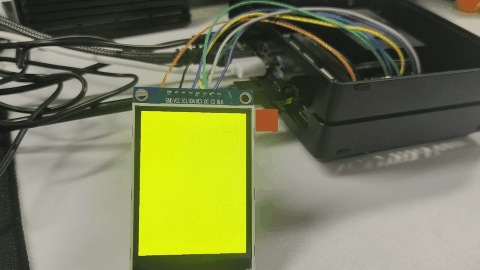
Figure 7. ST7789 display demo result
Code Explanation
- JetPack 5
- JetPack 6
- JetPack 7
SPI Initialization
The demo opens /dev/spidev0.0 and configures the SPI interface as follows.
| Parameter | Value |
|---|---|
| SPI device | /dev/spidev0.0 |
| SPI mode | SPI_MODE_0 |
| Bits per word | 8 |
| SPI speed | 24000000 Hz |
If your system generates a different SPI device node, modify the following line in the demo code:
spi_fd = open("/dev/spidev0.0", O_RDWR);
For example, if your device node is /dev/spidev1.0, change it to:
spi_fd = open("/dev/spidev1.0", O_RDWR);
GPIO Control
The demo uses sysfs GPIO to control the DC and RES pins.
| Signal | 40-pin Pin | sysfs GPIO path |
|---|---|---|
| DC | Pin 29 | /sys/class/gpio/PQ.05 |
| RES | Pin 31 | /sys/class/gpio/PQ.06 |
The DC pin is used to switch between command mode and data mode. The RES pin is used to reset the ST7789 display.
ST7789 Initialization
The demo initializes the ST7789 display with the following commands.
| Command | Description |
|---|---|
0x11 | Sleep Out |
0x3A | Pixel Format Set |
0x05 | RGB565 format |
0x36 | Memory Access Control |
0x21 | Display Inversion On |
0x29 | Display On |
Screen Fill Test
The demo uses RGB565 format to fill the full screen. The display resolution used in the demo is:
const int width = 240;
const int height = 320;
If your ST7789 display uses a different resolution, modify these values according to the actual screen size.
SPI Data Transfer
The full screen buffer is larger than a single small SPI transfer. Therefore, the demo sends display data in chunks:
const size_t CHUNK_SIZE = 4096;
This avoids transfer size limitations and makes the full-screen refresh more stable.
SPI Initialization
The demo opens /dev/spidev0.0 and configures the SPI interface as follows.
| Parameter | Value |
|---|---|
| SPI device | /dev/spidev0.0 |
| SPI mode | SPI_MODE_0 |
| Bits per word | 8 |
| SPI speed | 24000000 Hz |
If your system generates a different SPI device node, modify the following line in the demo code:
spi_fd = open("/dev/spidev0.0", O_RDWR);
For example, if your device node is /dev/spidev1.0, change it to:
spi_fd = open("/dev/spidev1.0", O_RDWR);
GPIO Control
The demo uses libgpiod to control the DC and RES pins. The program opens the GPIO chip, gets the GPIO lines by line offset, requests them as outputs, and then sets their values during display initialization and data transfer.
The GPIO chip and line offset are set in the following lines:
const char* GPIO_CHIP_NAME = "gpiochip0";
const unsigned int DC_LINE_OFFSET  = 29;
const unsigned int RES_LINE_OFFSET = 31;
If your gpiofind output is different, update these values before compiling the demo.
The DC pin is used to switch between command mode and data mode. The RES pin is used to reset the ST7789 display.
ST7789 Initialization
The demo initializes the ST7789 display with the following commands.
| Command | Description |
|---|---|
0x11 | Sleep Out |
0x3A | Pixel Format Set |
0x05 | RGB565 format |
0x36 | Memory Access Control |
0x21 | Display Inversion On |
0x29 | Display On |
Screen Fill Test
The demo uses RGB565 format to fill the full screen. The display resolution used in the demo is:
const int width = 240;
const int height = 320;
If your ST7789 display uses a different resolution, modify these values according to the actual screen size.
SPI Data Transfer
The full screen buffer is larger than a single small SPI transfer. Therefore, the demo sends display data in chunks:
const size_t CHUNK_SIZE = 4096;
This avoids transfer size limitations and makes the full-screen refresh more stable.
SPI Initialization
The demo opens /dev/spidev0.0 and configures the SPI interface as follows.
| Parameter | Value |
|---|---|
| SPI device | /dev/spidev0.0 |
| SPI mode | SPI_MODE_0 |
| Bits per word | 8 |
| SPI speed | 24000000 Hz |
If your system generates a different SPI device node, modify the following line in the demo code:
spi_fd = open("/dev/spidev0.0", O_RDWR);
For example, if your device node is /dev/spidev1.0, change it to:
spi_fd = open("/dev/spidev1.0", O_RDWR);
GPIO Control
The demo uses libgpiod to control the DC and RES pins. The program opens the GPIO chip, gets the GPIO lines by line offset, requests them as outputs, and then sets their values during display initialization and data transfer.
On JetPack 7, Pin 29 and Pin 31 should already be configured as gpio in the Jetson Expansion Header Tool. No manual pinmux register configuration is required before running the demo.
The GPIO chip and line offset are set in the following lines:
const char* GPIO_CHIP_NAME = "gpiochip0";
const unsigned int DC_LINE_OFFSET  = 29;
const unsigned int RES_LINE_OFFSET = 31;
If your gpiofind output is different, update these values before compiling the demo.
The DC pin is used to switch between command mode and data mode. The RES pin is used to reset the ST7789 display.
ST7789 Initialization
The demo initializes the ST7789 display with the following commands.
| Command | Description |
|---|---|
0x11 | Sleep Out |
0x3A | Pixel Format Set |
0x05 | RGB565 format |
0x36 | Memory Access Control |
0x21 | Display Inversion On |
0x29 | Display On |
Screen Fill Test
The demo uses RGB565 format to fill the full screen. The display resolution used in the demo is:
const int width = 240;
const int height = 320;
If your ST7789 display uses a different resolution, modify these values according to the actual screen size.
SPI Data Transfer
The full screen buffer is larger than a single small SPI transfer. Therefore, the demo sends display data in chunks:
const size_t CHUNK_SIZE = 4096;
This avoids transfer size limitations and makes the full-screen refresh more stable.
Troubleshooting
- JetPack 5
- JetPack 6
- JetPack 7
No /dev/spidev* Device Found
Possible causes:
- The SPI interface is not enabled.
- The Jetson-IO configuration was not saved.
- The device was not rebooted after enabling SPI.
- The device tree does not expose the SPI device node.
- The system image does not include the expected SPI configuration.
Suggested checks:
ls /dev/spidev*
If no SPI device is found, run Jetson-IO again and check whether SPI is enabled.
Permission Denied When Accessing SPI or GPIO
If you see a permission error when running the C++ demo, try running it with sudo:
sudo ./st7789_spi
You can also check the permission of the SPI device and GPIO nodes:
ls -l /dev/spidev*
ls -l /sys/class/gpio/PQ.05/value
ls -l /sys/class/gpio/PQ.06/value
GPIO Path Does Not Exist
If /sys/class/gpio/PQ.05 or /sys/class/gpio/PQ.06 does not exist, the GPIO pins may not have been exported correctly.
Please check the available GPIO nodes:
ls /sys/class/gpio/
Then export the GPIO pins again:
sudo sh -c 'echo 453 > /sys/class/gpio/export'
sudo sh -c 'echo 454 > /sys/class/gpio/export'
SPI Can Be Opened but the Display Shows Nothing
Possible causes:
- The display wiring is incorrect.
- The SPI device path is incorrect.
- The CS, DC, or RES pins are not connected correctly.
- The display controller is not ST7789.
- The display requires a different initialization sequence.
- The backlight pin is not powered.
Suggested checks:
- Confirm that
VCCis connected to Pin 1. - Confirm that
GNDis connected to Pin 6. - Confirm that
BLKis connected to Pin 17 and the backlight is on. - Confirm that
SCL,SDA, andCSare connected to Pin 23, Pin 19, and Pin 24. - Confirm that
RESandDCare connected to Pin 31 and Pin 29. - Reduce the SPI speed and test again.
- Confirm the display controller model from the display module datasheet.
Backlight Is On but No Image Is Displayed
If the backlight is on but no image is displayed, the power wiring may be correct, but SPI communication or display initialization may be incorrect.
Please check:
- Whether the correct SPI device is used.
- Whether the DC and RES pins are configured correctly.
- Whether the display driver matches the ST7789 controller.
- Whether the screen resolution is correct.
- Whether the display module requires row or column offset settings.
Image Color Is Abnormal
Possible causes:
- RGB and BGR color order mismatch.
- Display inversion setting is different.
- The
MADCTLparameter is not suitable for your panel. - The display module uses a slightly different ST7789 initialization sequence.
Suggested solutions:
- Try changing the
MADCTLvalue. - Try enabling or disabling display inversion.
- Check the ST7789 display module datasheet.
- Confirm whether your module uses RGB or BGR color order.
Image Direction Is Incorrect
If the image is rotated or mirrored, modify the MADCTL command parameter in the initialization function:
WriteCommand(0x36);
WriteData(0x08);
The correct value depends on the display module orientation.
Display Refresh Is Slow
Possible causes:
- SPI clock speed is too low.
- The program refreshes the full screen every time.
- The display module has limited refresh performance.
- The C++ demo uses a simple full-screen fill method for verification.
Suggested solutions:
- Increase SPI clock speed gradually.
- Avoid unnecessary full-screen refresh.
- Refresh only changed areas if your application supports it.
- Use the current color fill test only as a basic hardware verification demo.
No /dev/spidev* Device Found
Possible causes:
- The SPI interface is not enabled.
- The Jetson-IO configuration was not saved.
- The device was not rebooted after enabling SPI.
- The device tree does not expose the SPI device node.
- The system image does not include the expected SPI configuration.
Suggested checks:
ls /dev/spidev*
If no SPI device is found, run Jetson-IO again and check whether SPI is enabled.
Permission Denied When Accessing SPI or GPIO
If you see a permission error when running the C++ demo, try running it with sudo:
sudo ./st7789_spi_gpiod
You can also check the SPI device and GPIO character devices:
ls -l /dev/spidev*
ls -l /dev/gpiochip*
GPIO Line Cannot Be Found
If gpiofind PQ.05 or gpiofind PQ.06 returns no result, check the available GPIO lines:
gpioinfo
Then look for the GPIO names used by the DC and RES pins. If the GPIO chip name or line offset is different, update the following values in the demo code:
const char* GPIO_CHIP_NAME = "gpiochip0";
const unsigned int DC_LINE_OFFSET  = 29;
const unsigned int RES_LINE_OFFSET = 31;
Failed to Request GPIO Line
If the demo reports that it failed to request a GPIO line, possible causes include:
- The GPIO pinmux has not been configured as an output.
- The selected GPIO chip is incorrect.
- The selected line offset is incorrect.
- The GPIO line is already used by another process or driver.
- The program does not have permission to access
/dev/gpiochip*.
Suggested checks:
- Confirm that the pinmux registers for Pin 29 and Pin 31 have been configured. Re-run the
jetson-gpio-pinmux-lookupandbusybox devmemcommands from the GPIO Control section if needed. - Check the GPIO line status:
gpioinfo | grep -E "PQ.05|PQ.06"
If the line is already in use, stop the process that is using it or choose the correct GPIO line according to your hardware connection.
SPI Can Be Opened but the Display Shows Nothing
Possible causes:
- The display wiring is incorrect.
- The SPI device path is incorrect.
- The CS, DC, or RES pins are not connected correctly.
- The GPIO chip or line offset for DC/RES is incorrect.
- The display controller is not ST7789.
- The display requires a different initialization sequence.
- The backlight pin is not powered.
Suggested checks:
- Confirm that
VCCis connected to Pin 1. - Confirm that
GNDis connected to Pin 6. - Confirm that
BLKis connected to Pin 17 and the backlight is on. - Confirm that
SCL,SDA, andCSare connected to Pin 23, Pin 19, and Pin 24. - Confirm that
RESandDCare connected to Pin 31 and Pin 29. - Confirm the GPIO chip and line offset with
gpiofindorgpioinfo. - Reduce the SPI speed and test again.
- Confirm the display controller model from the display module datasheet.
Backlight Is On but No Image Is Displayed
If the backlight is on but no image is displayed, the power wiring may be correct, but SPI communication, GPIO control, or display initialization may be incorrect.
Please check:
- Whether the correct SPI device is used.
- Whether the correct GPIO chip and line offsets are used for DC and RES.
- Whether the display driver matches the ST7789 controller.
- Whether the screen resolution is correct.
- Whether the display module requires row or column offset settings.
Image Color Is Abnormal
Possible causes:
- RGB and BGR color order mismatch.
- Display inversion setting is different.
- The
MADCTLparameter is not suitable for your panel. - The display module uses a slightly different ST7789 initialization sequence.
Suggested solutions:
- Try changing the
MADCTLvalue. - Try enabling or disabling display inversion.
- Check the ST7789 display module datasheet.
- Confirm whether your module uses RGB or BGR color order.
Image Direction Is Incorrect
If the image is rotated or mirrored, modify the MADCTL command parameter in the initialization function:
WriteCommand(0x36);
WriteData(0x08);
The correct value depends on the display module orientation.
Display Refresh Is Slow
Possible causes:
- SPI clock speed is too low.
- The program refreshes the full screen every time.
- The display module has limited refresh performance.
- The C++ demo uses a simple full-screen fill method for verification.
Suggested solutions:
- Increase SPI clock speed gradually.
- Avoid unnecessary full-screen refresh.
- Refresh only changed areas if your application supports it.
- Use the current color fill test only as a basic hardware verification demo.
No /dev/spidev* Device Found
Possible causes:
- The SPI interface is not enabled.
- The Jetson-IO configuration was not saved.
- The device was not rebooted after enabling SPI.
- The device tree does not expose the SPI device node.
- The system image does not include the expected SPI configuration.
Suggested checks:
ls /dev/spidev*
If no SPI device is found, run Jetson-IO again and check whether spi1 is enabled.
Permission Denied When Accessing SPI or GPIO
If you see a permission error when running the C++ demo, try running it with sudo:
sudo ./st7789_spi_gpiod
You can also check the SPI device and GPIO character devices:
ls -l /dev/spidev*
ls -l /dev/gpiochip*
GPIO Line Cannot Be Found
If gpiofind PQ.05 or gpiofind PQ.06 returns no result, check the available GPIO lines:
gpioinfo
Then look for the GPIO names used by the DC and RES pins. If the GPIO chip name or line offset is different, update the following values in the demo code:
const char* GPIO_CHIP_NAME = "gpiochip0";
const unsigned int DC_LINE_OFFSET  = 29;
const unsigned int RES_LINE_OFFSET = 31;
Also confirm that Pin 29 and Pin 31 are configured as gpio in the Jetson Expansion Header Tool.
Failed to Request GPIO Line
If the demo reports that it failed to request a GPIO line, possible causes include:
- Pin 29 or Pin 31 is not configured as
gpioin the Jetson Expansion Header Tool. - The selected GPIO chip is incorrect.
- The selected line offset is incorrect.
- The GPIO line is already used by another process or driver.
- The program does not have permission to access
/dev/gpiochip*.
Suggested checks:
- Open Jetson-IO again and confirm that Pin 29 (
extperiph3_clk) and Pin 31 (extperiph4_clk) are set togpio. - Check the GPIO line status:
gpioinfo | grep -E "PQ.05|PQ.06"
If the line is already in use, stop the process that is using it or choose the correct GPIO line according to your hardware connection.
SPI Can Be Opened but the Display Shows Nothing
Possible causes:
- The display wiring is incorrect.
- The SPI device path is incorrect.
- The CS, DC, or RES pins are not connected correctly.
- The GPIO chip or line offset for DC/RES is incorrect.
- Pin 29 or Pin 31 is not configured as
gpioin Jetson-IO. - The display controller is not ST7789.
- The display requires a different initialization sequence.
- The backlight pin is not powered.
Suggested checks:
- Confirm that
VCCis connected to Pin 1. - Confirm that
GNDis connected to Pin 6. - Confirm that
BLKis connected to Pin 17 and the backlight is on. - Confirm that
SCL,SDA, andCSare connected to Pin 23, Pin 19, and Pin 24. - Confirm that
RESandDCare connected to Pin 31 and Pin 29. - Confirm the GPIO chip and line offset with
gpiofindorgpioinfo. - Confirm that Pin 29 and Pin 31 are configured as
gpioin Jetson-IO. - Reduce the SPI speed and test again.
- Confirm the display controller model from the display module datasheet.
Backlight Is On but No Image Is Displayed
If the backlight is on but no image is displayed, the power wiring may be correct, but SPI communication, GPIO control, or display initialization may be incorrect.
Please check:
- Whether the correct SPI device is used.
- Whether the correct GPIO chip and line offsets are used for DC and RES.
- Whether Pin 29 and Pin 31 are configured as
gpioin Jetson-IO. - Whether the display driver matches the ST7789 controller.
- Whether the screen resolution is correct.
- Whether the display module requires row or column offset settings.
Image Color Is Abnormal
Possible causes:
- RGB and BGR color order mismatch.
- Display inversion setting is different.
- The
MADCTLparameter is not suitable for your panel. - The display module uses a slightly different ST7789 initialization sequence.
Suggested solutions:
- Try changing the
MADCTLvalue. - Try enabling or disabling display inversion.
- Check the ST7789 display module datasheet.
- Confirm whether your module uses RGB or BGR color order.
Image Direction Is Incorrect
If the image is rotated or mirrored, modify the MADCTL command parameter in the initialization function:
WriteCommand(0x36);
WriteData(0x08);
The correct value depends on the display module orientation.
Display Refresh Is Slow
Possible causes:
- SPI clock speed is too low.
- The program refreshes the full screen every time.
- The display module has limited refresh performance.
- The C++ demo uses a simple full-screen fill method for verification.
Suggested solutions:
- Increase SPI clock speed gradually.
- Avoid unnecessary full-screen refresh.
- Refresh only changed areas if your application supports it.
- Use the current color fill test only as a basic hardware verification demo.
Summary
In this wiki, we introduced how to connect an SPI display to the Seeed reComputer J4012 Classic through the 40-pin header. The general SPI display workflow includes wiring the display, enabling the SPI interface, checking the SPI device node, installing dependencies, compiling a C++ demo, and running a display test. JetPack 5 uses sysfs GPIO, JetPack 6 uses libgpiod with manual pinmux configuration, and JetPack 7 uses libgpiod with GPIO pins configured directly in the Jetson Expansion Header Tool.
The ST7789 SPI LCD was used as the example display module in this guide. For other SPI displays, the overall process is similar, but the display driver, resolution, initialization sequence, and wiring details should be adjusted according to the actual display module.
Resources
Tech Support & Product Discussion
Thank you for choosing our products! We are here to provide you with different support to ensure that your experience with our products is as smooth as possible. We offer several communication channels to cater to different preferences and needs.