Getting Started with LED Driver Board for XIAO
LED Driver Board for XIAO is a compact yet powerful solution supporting both 5V and 12V LED strips, including popular addressable RGB LEDs such as NeoPixel WS2812, WS2813, WS2815. Compatible with all XIAO boards, it enables smart control and automation through WLED and Home Assistant when using XIAO ESP32 Series, while offering flexible power options and comprehensive protection for safe, reliable operation in your lighting setup.
Introduction
Feature
-
Wide LED Compatibility
Versatile driver supporting both 5V/3A and 12V/2A LED strips with built-in power regulation. Compatible with single-color and addressable RGB LEDs including NeoPixel WS2811, WS2812(B), WS2813, WS2815, SK6812, and other 1-wire protocol LEDs, providing extensive lighting options.
-
XIAO-Compatibility for Smart Control
Designed for all Seeed Studio XIAO boards. When paired with XIAO ESP32 Series (ESP32-C3/S3/C6), unlock smart features through:
- WLED app support - Control colors, effects, brightness, and create custom animations (XIAO ESP32C3 is highly recommended)
- Home Assistant integration via ESPHome - Enable remote control, automation, and smart home scenarios
-
Grove Ecosystem Compatibility
The onboard plug-and-play Grove interface is compatible with over 400 Seeed Studio modules, allowing you to easily enhance lighting interactivity with the environment and motion for smarter, personalized effects:
-
For AI Vision Detection -
For Temperature & Humidity DetectionGrove - Temperature & Humidity Sensor (DHT11)
Grove - AHT20 I2C Industrial Grade Temperature&Humidity Sensor
-
For Motion Detection
-
Specification
| Item | Detail |
|---|---|
| Power Input | DC 12V/2A |
| LED Power Support | DC 12V / DC 5V |
| Max Operating Current | 12V/2A 5V/3A |
| LED Connector | 4 Pin 3.81mm Screw Terminal Block Connector: 12V | 5V | A0 | GND |
| Grove I²C Connector | D5 | D4 | 5V | GND |
| User Button | D3 |
| User Pin Header | SPI x1, Uart x1, Digital x2 |
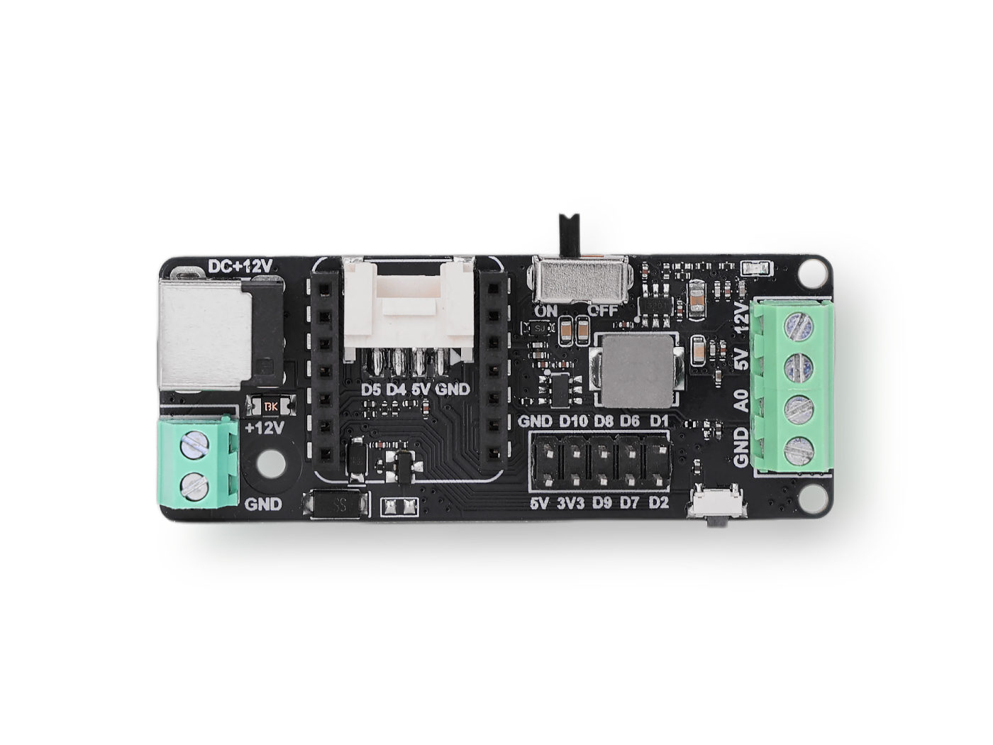
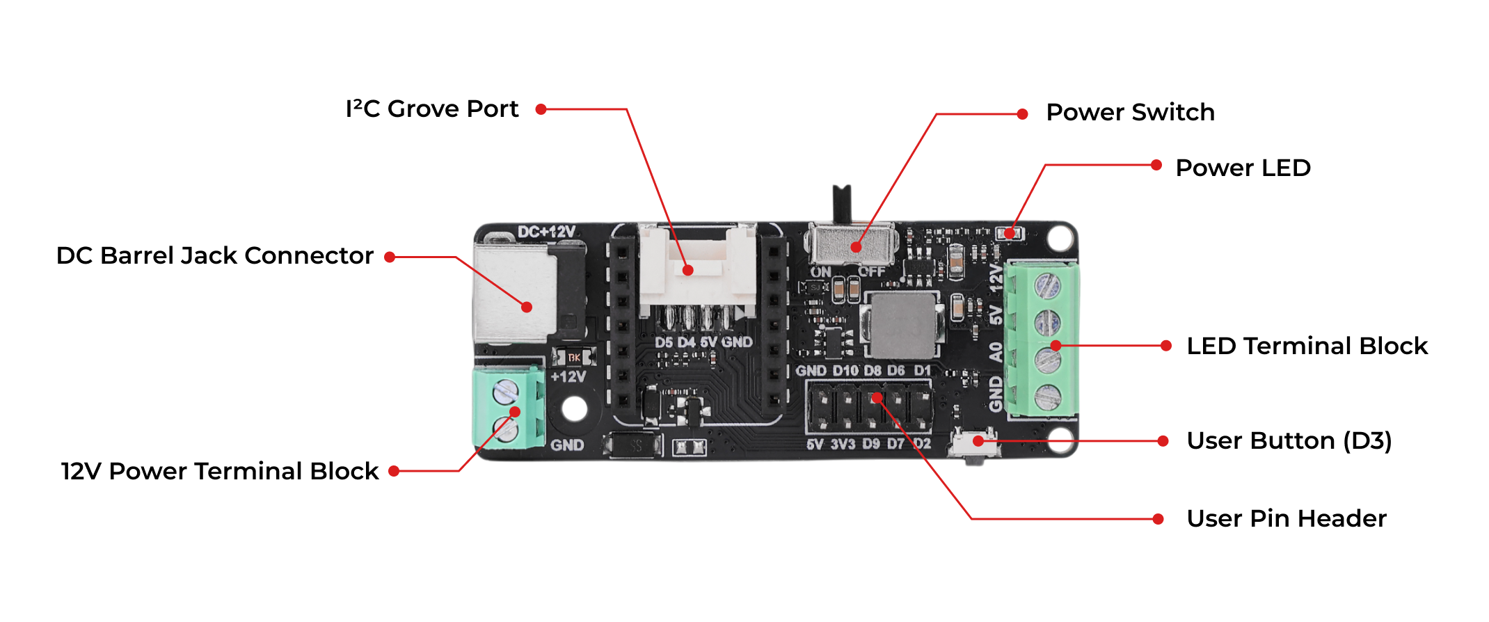
Hardware Overview
Adapted power input
- PowerAdapter, 12V/2A/24W, European Standard Plug, DC Output
- PowerAdapter, 12V/2A/24W, American Standard Plug, DC Output
- Other DC 12V Power Adapter with 5.5mm x 2.1mm x 10±0.3mm Plug
- DC 12V Wire
Supported LEDs Guide
| Product | Name | Operating Voltage | Connect via |
|---|---|---|---|
 | Grove - RGB LED (WS2813 Mini) | 5V | Grove |
 | Grove - RGB LED Stick (10-WS2813 Mini) | 5V | Grove |
 | Grove - RGB LED Stick (15-WS2813 Mini) | 5V | Grove |
 | Grove - RGB LED Stick (20-WS2813 Mini) | 5V | Grove |
 | Grove - RGB LED Ring (16-WS2813 Mini) | 5V | Grove |
 | Grove - RGB LED Ring (20-WS2813 Mini) | 5V | Grove |
 | Grove - RGB LED Ring (24-WS2813 Mini) | 5V | Grove |
 | Grove - Ultimate RGB LED Ring | 5V | Grove |
 | Grove - WS2813B RGB LED Flexi-Strip 30 LED/m - 1m | 5V | Terminal Block |
 | Grove - WS2813B RGB LED Flexi-Strip 60 LED/m - 1m | 5V | Terminal Block |
 | Grove - WS2813 RGB LED Strip Waterproof - 30 LED/m - 1m | 5V | Grove |
 | Grove - WS2813 RGB LED Strip Waterproof - 60 LED/m - 1m | 5V | Grove |
Getting Started
This LED driver board is designed specifically for the Seeed Studio XIAO series. Its functionality varies depending on the paired XIAO microcontroller. For example, when used with the XIAO nRF52840, it can read onboard IMU data to dynamically change LED colors. When paired with ESP32 series boards, it can be integrated into Home Assistant for seamless smart home control. Additionally, with the XIAO ESP32-C3, it supports running WLED for advanced LED effects. Follow the tutorial below to explore these capabilities in detail.
Play with Arduino
You need to configure the Arduino environment for the XIAO and add the on-board package.
If this is your first time using Arduino, we highly recommend you to refer to Getting Started with Arduino.
Software Preparation
Step 1. Launch the Arduino application.
Step 2. Select your development board model and add it to the Arduino IDE.
-
If you want to use Seeed Studio XIAO SAMD21 for the later routines, please refer to this tutorial to finish adding.
-
If you want to use Seeed Studio XIAO RP2040 for the later routines, please refer to this tutorial to finish adding.
-
If you want to use Seeed Studio XIAO RP2350 for the later routines, please refer to this tutorial to finish adding.
-
If you want to use Seeed Studio XIAO nRF52840 for the later routines, please refer to this tutorial to finish adding.
-
If you want to use Seeed Studio XIAO ESP32C3 for the later routines, please refer to this tutorial to finish adding.
-
If you want to use Seeed Studio XIAO ESP32C6 for the later routines, please refer to this tutorial to finish adding.
-
If you want to use Seeed Studio XIAO ESP32S3 for the later routines, please refer to this tutorial to finish adding.
-
If you want to use Seeed Studio XIAO RA4M1 for the later routines, please refer to this tutorial to finish adding.
-
If you want to use Seeed Studio XIAO MG24 for the later routines, please refer to this tutorial to finish adding.
Step 3. Install libraries needed.
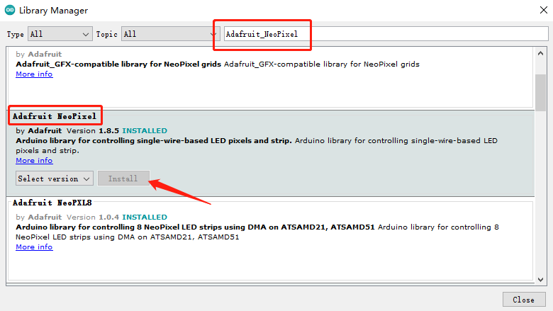
- Open Arduino IDE, navigate to Sketch > Include Library > Manage Libraries... to search the library, type the keyword "Adafruit_NeoPixel" library in Ardunio library Manager and install the lastest version.
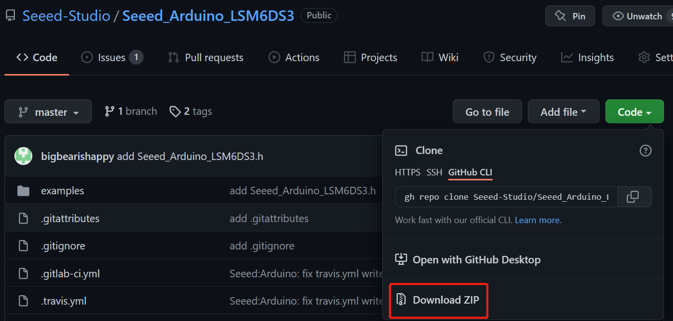
- Download Seeed_Arduino_LSM6DS3 Library as a zip file, open Arduino IDE, navigate to Sketch > Include Library > Add .ZIP Library... and open the downloaded zip file.
Simple Example
Step 1. Hardware preparation
| Seeed Studio XIAO RP2350 | LED Driver Board for XIAO | Grove - RGB LED Stick (15-WS2813 Mini) |
|---|---|---|
 |  | |
Step 2. Connect Seeed Studio XIAO RP2350, LED Driver Board for XIAO and Grove - RGB LED Stick (15-WS2813 Mini) as show below:
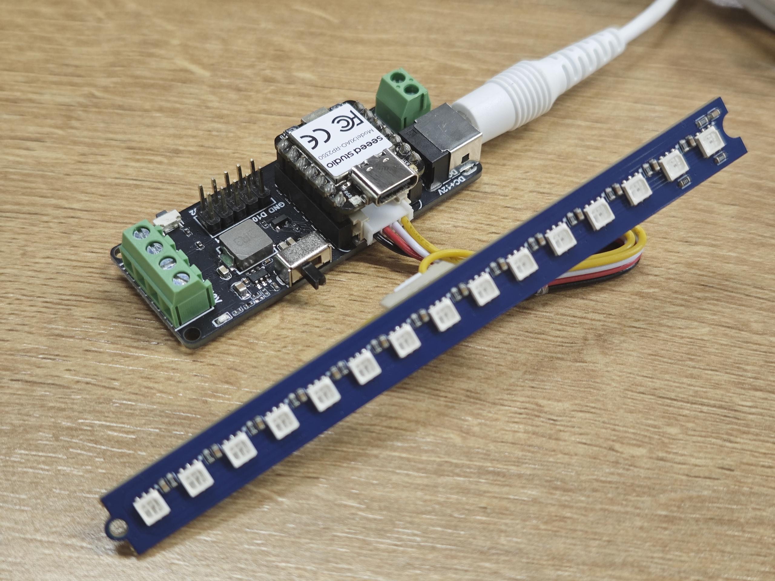
Step 3. The following sample program is control LEDs containing 3 NeoPixel so that each of the three beads displays the colors red, green, and blue
#include <Adafruit_NeoPixel.h>

// Which pin on the Arduino is connected to the NeoPixels?
#define PIN D5

// How many NeoPixels are attached to the Arduino?
#define NUMPIXELS 3

// When setting up the NeoPixel library, we tell it how many pixels,
// and which pin to use to send signals. Note that for older NeoPixel
// strips you might need to change the third parameter -- see the
// strandtest example for more information on possible values.
Adafruit_NeoPixel pixels(NUMPIXELS, PIN, NEO_GRB + NEO_KHZ800);

void setup() {
  pixels.begin(); // INITIALIZE NeoPixel strip object
}

void loop() {
  pixels.clear(); // Set all pixel colors to 'off'

  // pixels.Color() takes RGB values, from 0,0,0 up to 255,255,255
  // The first NeoPixel in a strand is #0, second is 1, all the way up
  pixels.setPixelColor(0, pixels.Color(255, 0, 0));
  pixels.setPixelColor(1, pixels.Color(0, 255, 0));
  pixels.setPixelColor(2, pixels.Color(0, 0, 255));
  // pixels.setBrightness() takes brightness values, from 0 up to 255
  pixels.setBrightness(255);

  pixels.show();   // Send the updated pixel colors to the hardware.

}
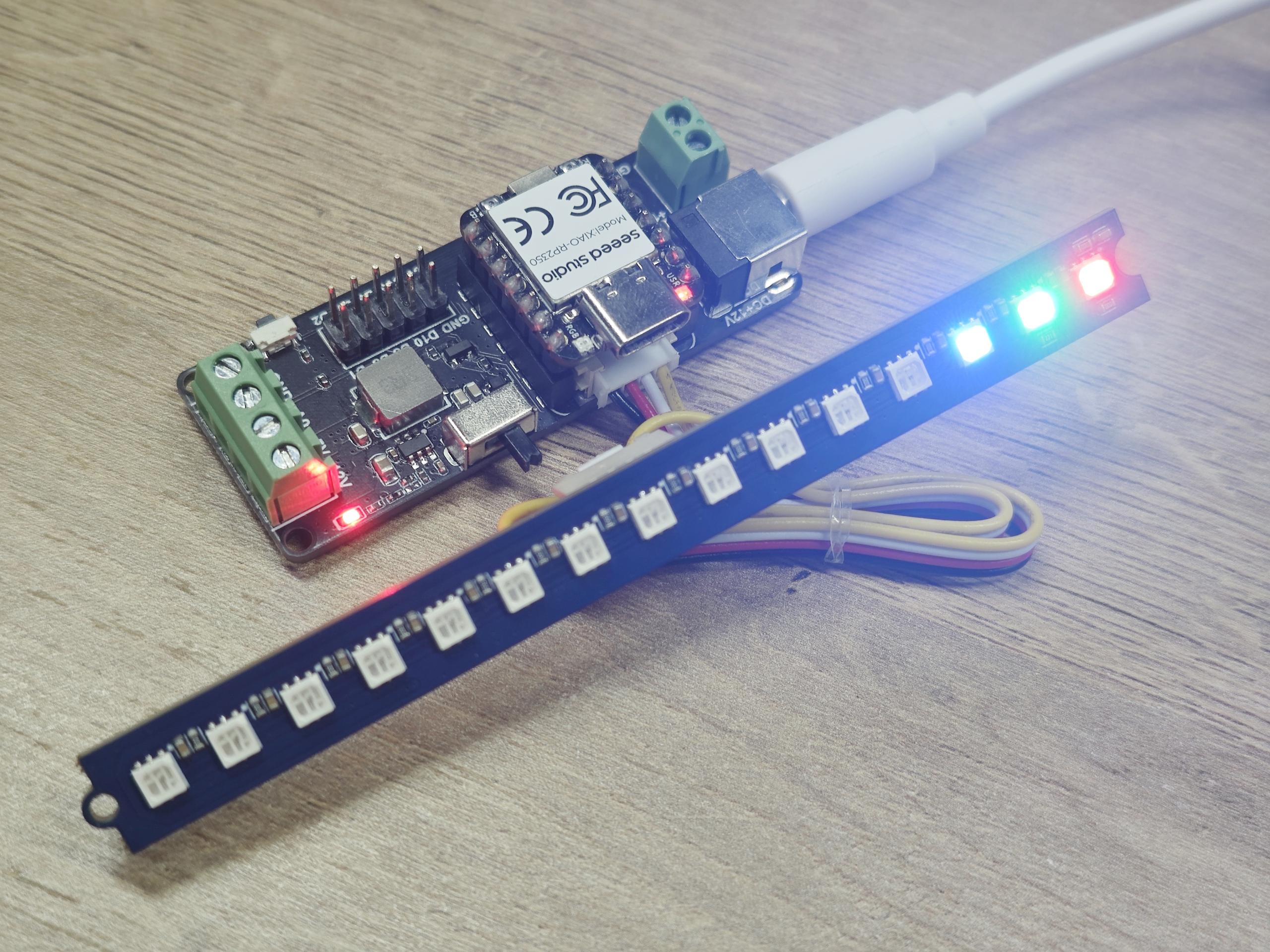
Upload the program and power LED Driver Board, if all goes well, you can see like this:
Motion-Color Sync LED
Step 1. Hardware preparation
| XIAO nRF52840 | LED Driver Board for XIAO | WS2812 LED |
|---|---|---|
|  | |
Step 2. Connect Seeed Studio XIAO nRF52840, LED Driver Board for XIAO and WS2812 LED as show below:
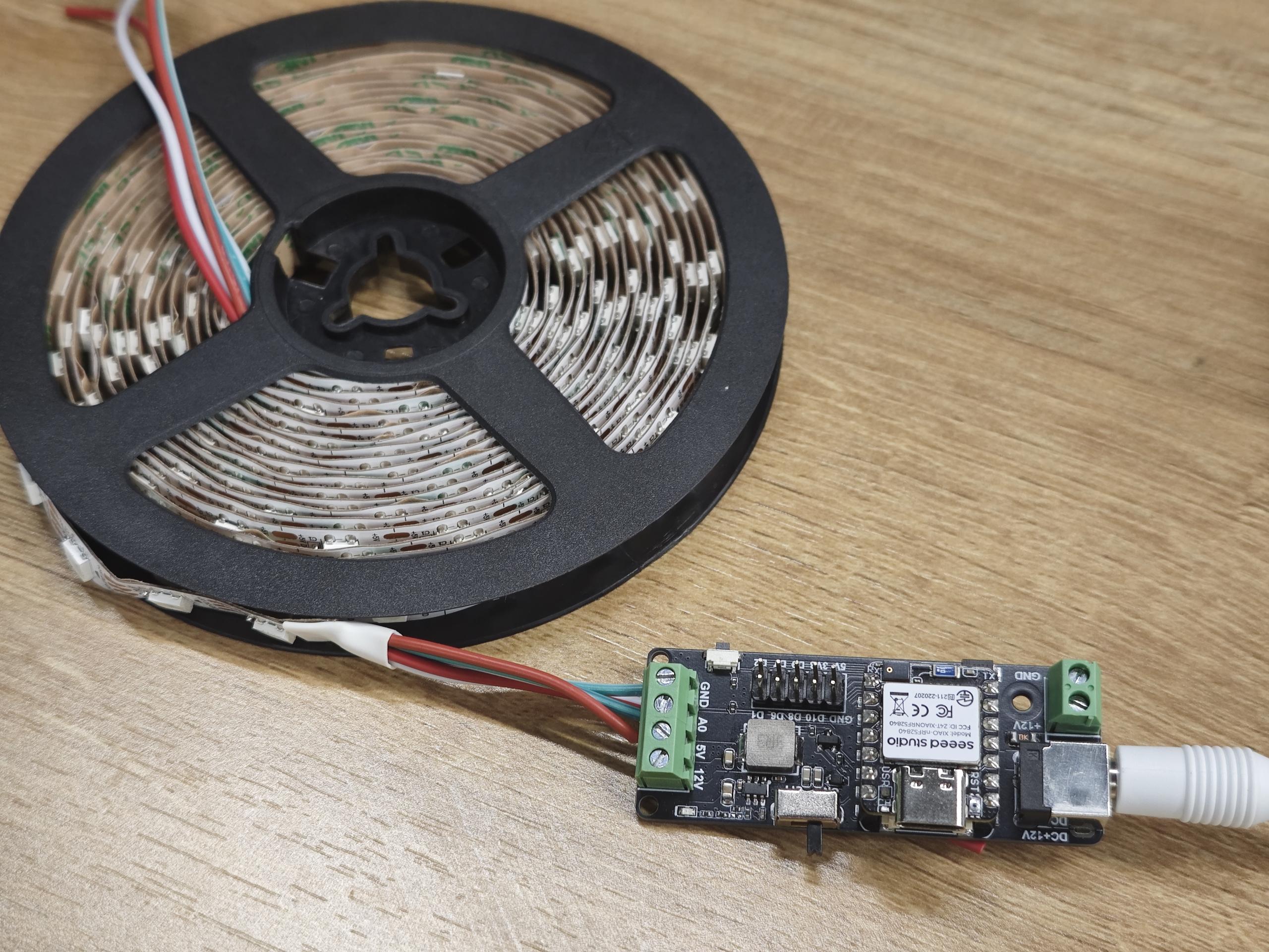
Step 3. The following code works by reading the data from the XIAO nRF52840 onboard LSM6DS3 acceleration sensor and changing the color of LED strip in real time, with the color mapped from the current acceleration value.
#include <Arduino.h>
#include "LSM6DS3.h"
#include <Adafruit_NeoPixel.h>
#include "Wire.h"
#include "math.h"

// Define the pin connected to the NeoPixel data input
#define PIN A0

// Total number of NeoPixel LEDs
#define NUMPIXELS 300

// Create a NeoPixel strip object
Adafruit_NeoPixel pixels(NUMPIXELS, PIN, NEO_GRB + NEO_KHZ800);

// Variables for accelerometer data
float ax = 0;
float ay = 0;
float az = 0;

// RGB color components
uint8_t r = 0;
uint8_t g = 0;
uint8_t b = 0;

// Packed 24-bit RGB color value
uint32_t packedRGB = 0;

// Create an instance of the LSM6DS3 IMU in I2C mode at address 0x6A
LSM6DS3 myIMU(I2C_MODE, 0x6A);


void setup() {

    Serial.begin(9600);

    // Initialize the IMU sensor and check for errors
    if (myIMU.begin() != 0) {
        Serial.println("Device error");
    } else {
        Serial.println("Device OK!");
    }

    // Initialize the NeoPixel strip
    pixels.begin();
}


void loop() {
    // Read acceleration values from the IMU
    ax = myIMU.readFloatAccelX();
    ay = myIMU.readFloatAccelY();
    az = myIMU.readFloatAccelZ();

    // Map acceleration (-1g to +1g) to RGB values (0 to 255)
    // Centered at 128 to allow both positive and negative variations
    r = constrain(ax * 100 + 128, 0, 255);
    g = constrain(ay * 100 + 128, 0, 255);
    b = constrain(az * 100 + 128, 0, 255);

    // Combine RGB components into a single 24-bit color value
    packedRGB = (r << 16) | (g << 8) | b;

    // Clear all existing pixels
    pixels.clear();

    // Fill all LEDs with the computed color
    pixels.fill(packedRGB, 0, NUMPIXELS);
    pixels.setBrightness(255);
    pixels.show();
    delay(100);
}
Upload the program and power LED Driver Board, if all goes well, you can see like this:
When you shake the module, the color of the light strip changes. The more violent the shaking, the brighter the color.
Play with Home Assistant via ESPHome
Hardware Preparation
| Home Assistant Devices |
|---|
 |
Software Preparation

ESPHome is a tool which aims to make managing your ESP boards as simple as possible. It reads in a YAML configuration file and creates custom firmware which it installs on your ESP device. Devices or sensors added in ESPHome’s configuration will automatically show up in Home Assistant’s UI. ESPHome can help you connect and send the data to Home Assistant devices.
If this is your first time using Home Assistant and ESPHome, you can follow here for a step-by-step guide on installing Home Assistant.
ESPHome is available as a Home Assistant Add-On and can simply be installed via the add-on store.
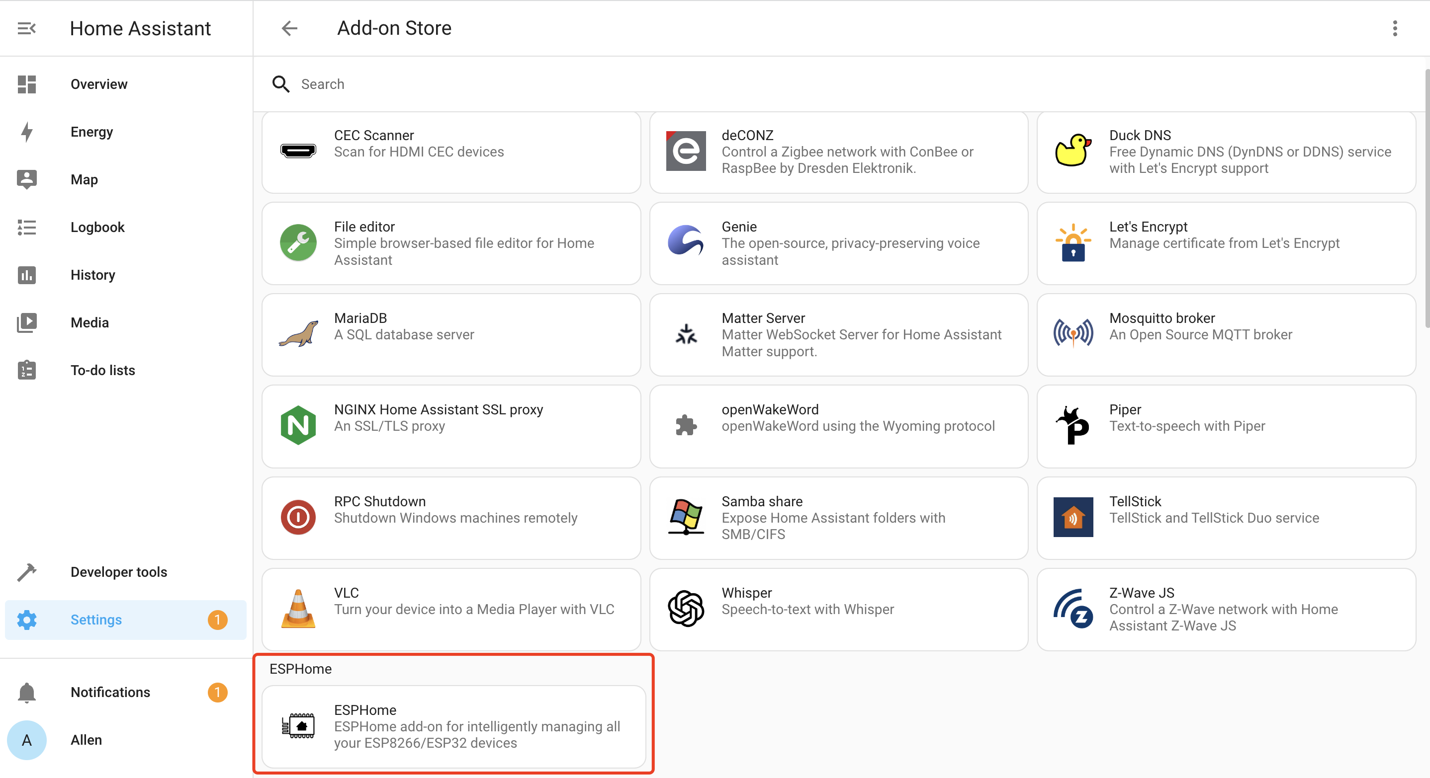
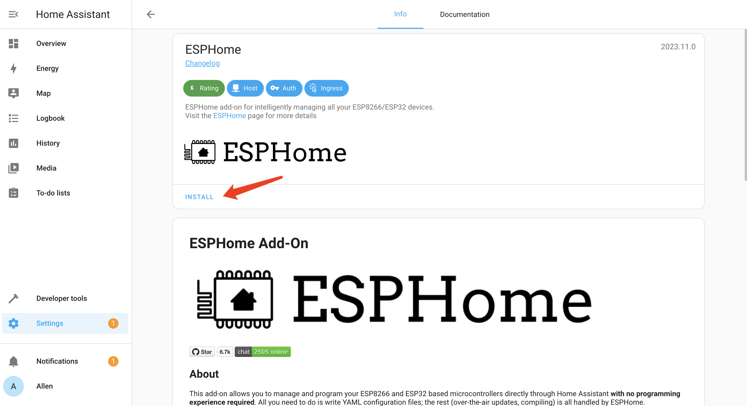
- Step 1. Click INSTALL
- Step 2. Enable all the options and click START
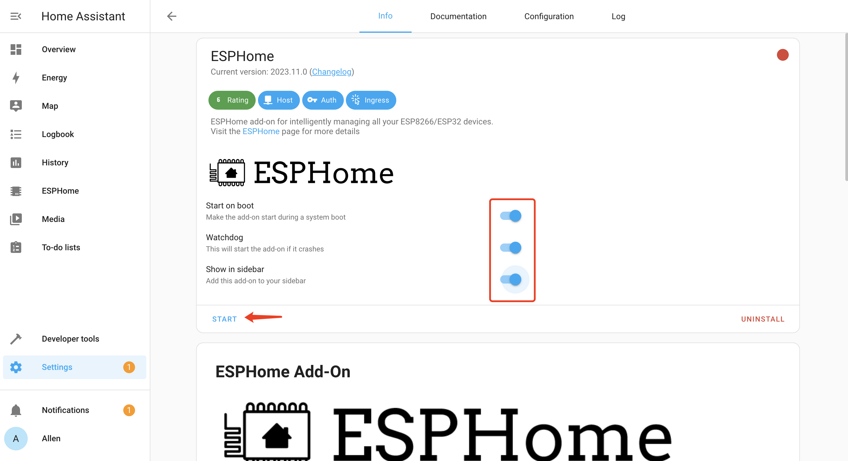
You will see the following window if ESPHome is successfully loaded
Temp-Color Sync LEDs
Step 1. Hardware preparation
| XIAO ESP32S3 | LED Driver Board for XIAO | Grove - Temperature & Humidity Sensor (DHT11) | WS2812 LED |
|---|---|---|---|
 | |  | |
Step 2. Connect Seeed Studio XIAO ESP32S3, LED Driver Board for XIAO and WS2812 LED as show below:

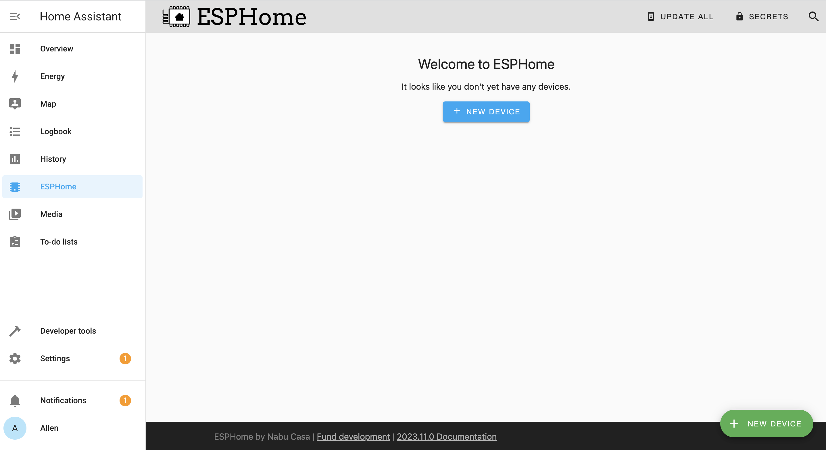
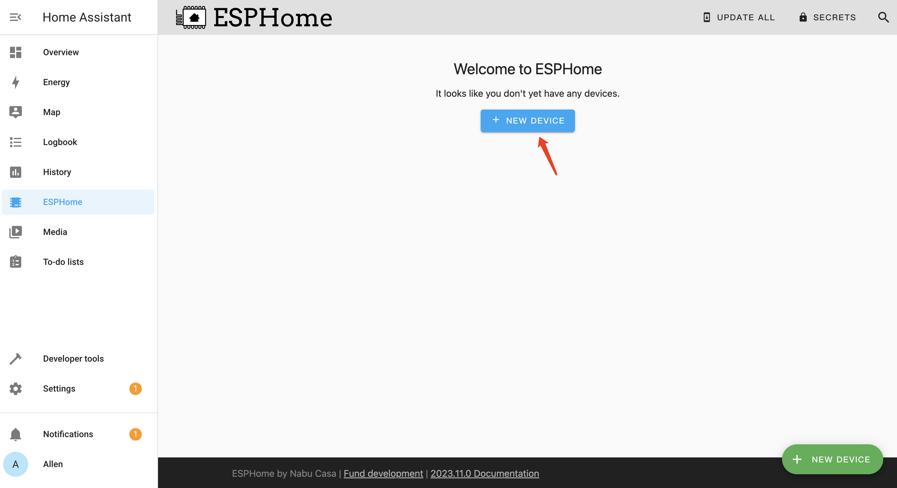
Step 3. Open ESPHome page, and click + NEW DEVICE
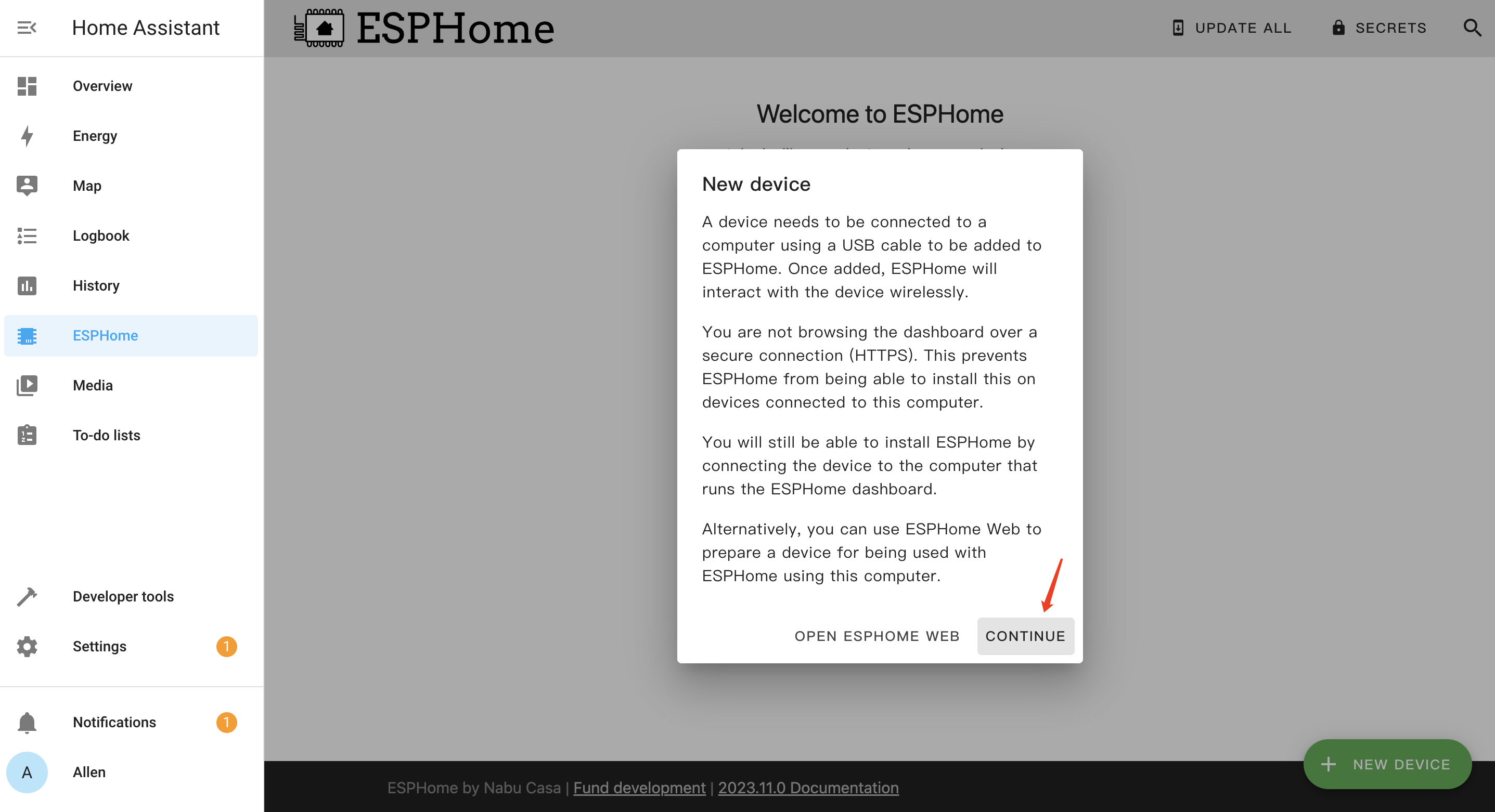
Step 4. Click CONTINUE
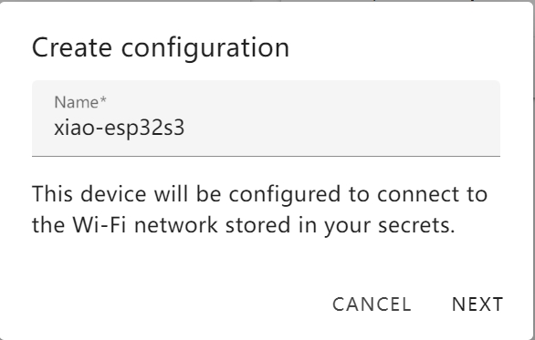
Step 5. Enter a Name for the device and enter WiFi credentials such as Network name and Password. Then click NEXT
Step 6. Select ESP32-S3 and click
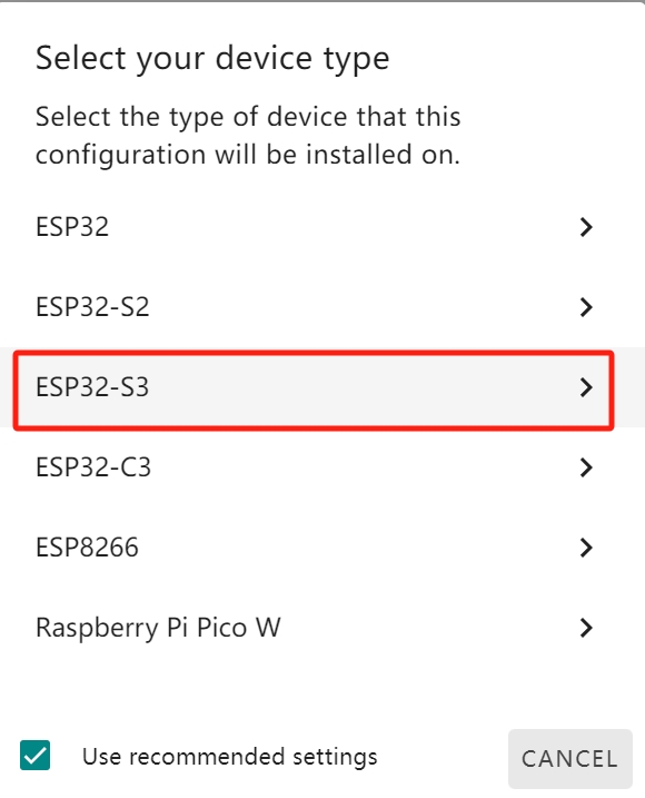
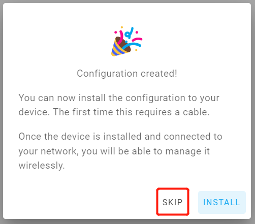
Step 7. Click SKIP because we will configure this board manually
Step 8. Click EDIT under the newly created board
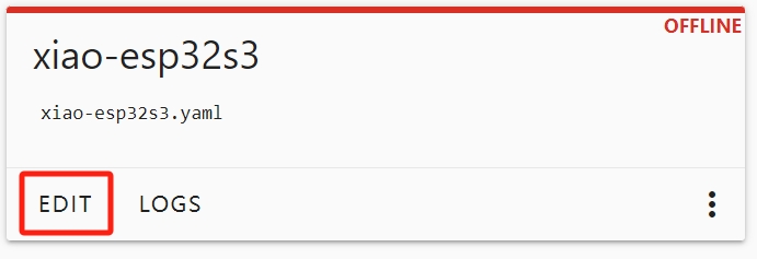
Step 9. Copy the follow codes to end of .yaml file, the XIAO ESP32S3 reads temperature from a DHT11 sensor and changes the color of an RGB LED based on how far the temperature is from a target value, using blue for cold, red for hot, and green for normal.
# DHT11 temperature and humidity sensor
sensor:
  - platform: dht
    pin: GPIO6
    model: DHT11  # Change to DHT22 or AM2302 if using a different model
    temperature:
      name: "Temperature"
      id: temp_sensor
    humidity:
      name: "Humidity"
    update_interval: 3s # Read new values every 3 seconds

# RGB LED (WS2812 single LED)
light:
  - platform: neopixelbus
    variant: ws2813  # ⚠️ Adjust based on your actual LED type (e.g., ws2812, ws2813, sk6812)
    type: GRB  # Color order (Green-Red-Blue)
    pin: GPIO1
    num_leds: 50 # Total number of NeoPixel LEDs
    name: "Temperature Color LED"
    id: rgb_led
    restore_mode: ALWAYS_ON
    default_transition_length: 0s

# Adjustable center temperature threshold
number:
  - platform: template
    name: "Target Temperature" # Center temperature value
    id: target_temp
    optimistic: true
    min_value: 0
    max_value: 40
    step: 0.1
    initial_value: 20.0 # Default center temperature (°C)

  - platform: template
    name: "Temperature Tolerance" # Tolerance around target temperature
    id: temp_tolerance
    optimistic: true
    min_value: 0
    max_value: 10
    step: 0.1
    initial_value: 5.0 # Default tolerance value (°C)

# Every 3 seconds, the LED color is updated:
# - Blue if too cold (below center - tolerance),
# - Red if too hot (above center + tolerance),
# - Green if temperature is close to the center,
# - Gradient between blue–green–red in transitional ranges.
#- If the temperature is not available, the LED blinks purple to indicate a sensor error.

interval:
  - interval: 3s
    then:
      - lambda: |-
          float t = id(temp_sensor).state;
          float center = id(target_temp).state;
          float tolerance = id(temp_tolerance).state;
          float r = 0.0, g = 0.0, b = 0.0;
          float ratio = 0.0;

          if (isnan(t)) {
            // Flash purple to indicate missing temperature
            static bool blink = false;
            blink = !blink;
            auto call = id(rgb_led).turn_on();
            call.set_rgb(blink ? 0.5 : 0.0, 0.0, blink ? 0.5 : 0.0);
            call.perform();
            return;
          }

          // Calculate RGB values based on temperature
          if (t <= (center - tolerance)) {
            b = 1.0;
            g = 0.0;
          } else if (t >= (center + tolerance)) {
            r = 1.0;
            g = 0.0;
          } else if (t <= center) {
            ratio = (center - t) / tolerance;
            b = ratio;
            g = 1.0 - ratio;
          } else {
            ratio = (t - center) / tolerance;
            r = ratio;
            g = 1.0 - ratio;
          }


          // Update LED
            auto call = id(rgb_led).turn_on();
            call.set_rgb(r, g, b);
            call.perform();
Step 10. Click on the Install button in the top right hand corner. Then select the last item Manual download, Select Modern format
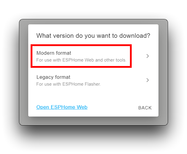
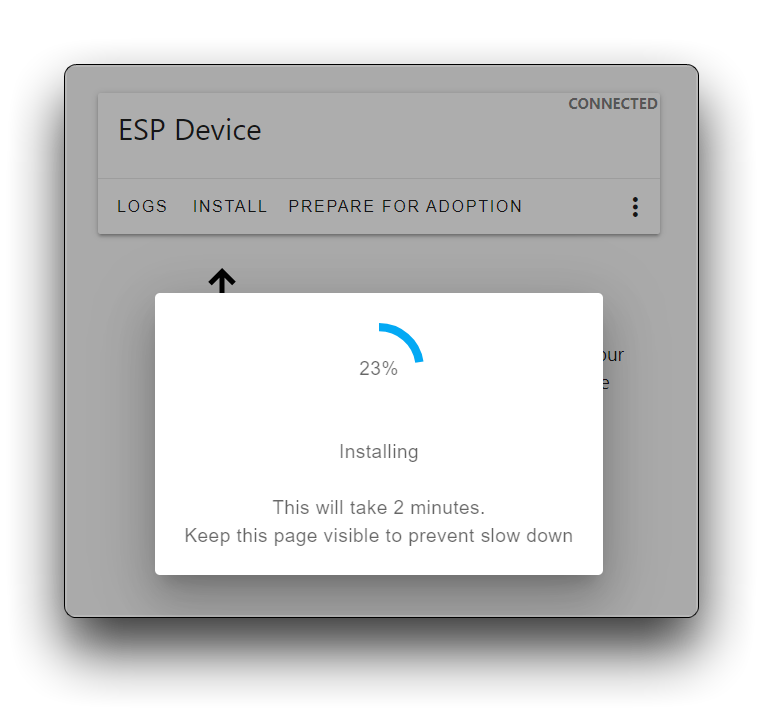
It will then take a long time to download and compile, so please be patient. Once everything is ready, the firmware will be automatically downloaded to your computer.
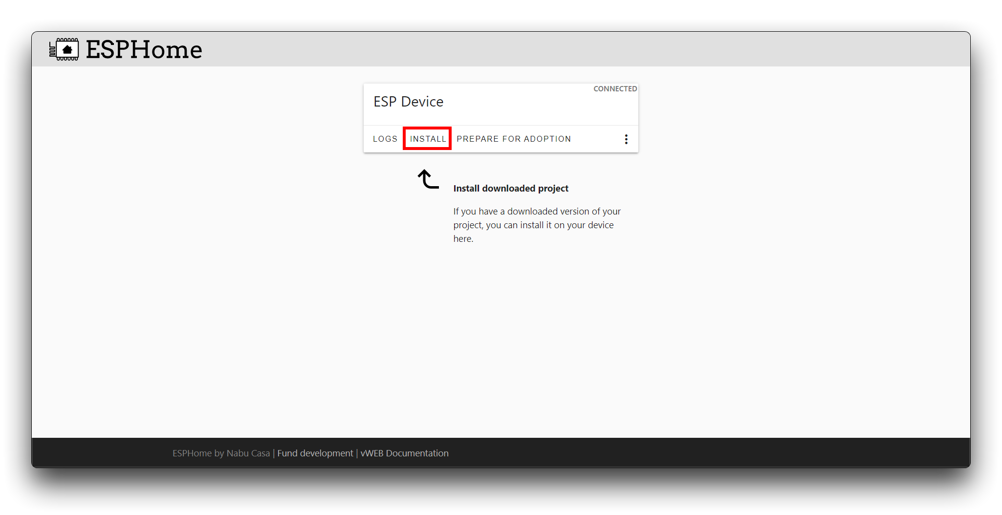
Step 11. Using the ESPhome Web tool to upload the firmware to XIAO ESP32S3, click CONNECT
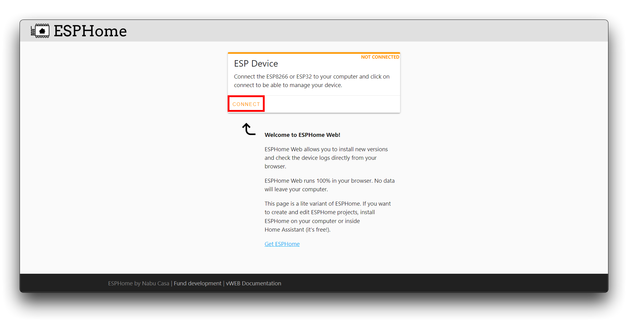
Select the XIAO ESP32 serial port in the popup window, click INSTALL and then select the .bin file downloaded from above steps.
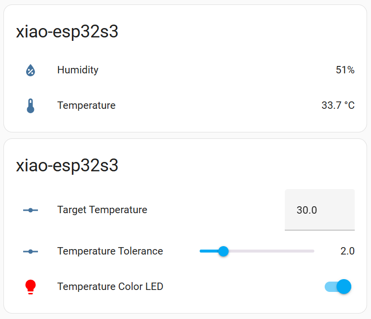
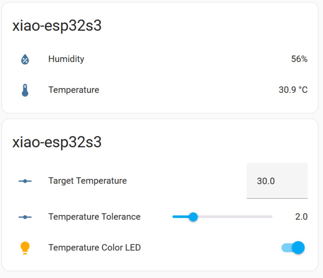
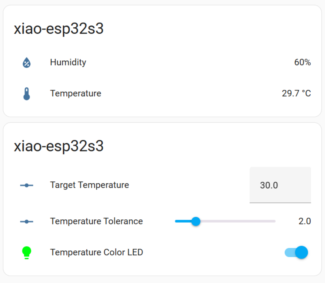
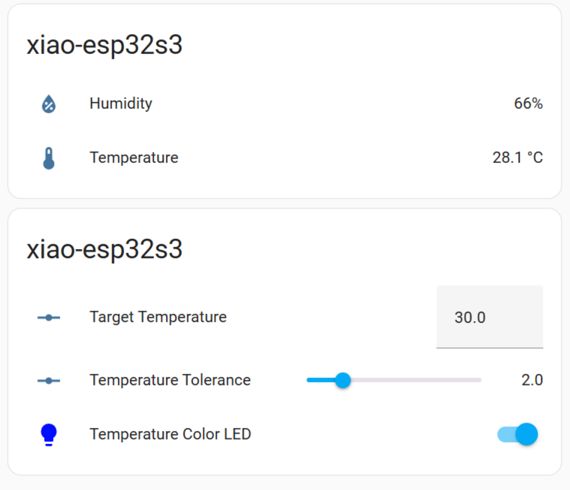
Step 11. Once install successfully, you can see like this:
When cold air is blown to the temperature and humidity sensor, the color of the light strip gradually changes from red to blue as the temperature drops.
Step 12. Add to Dashboard
Open Setting >> Devices & Services, you can find your ESPhome Device, click ADD and add it to dashboard, you can see like this:

Run WLED
Hardware Perparation
| XIAO ESP32C3 | LED Driver Board for XIAO | WS2812 LED |
|---|---|---|
 | | |
Connect Seeed Studio XIAO nRF52840, LED Driver Board for XIAO and WS2812 LED as show below:

Install WLED
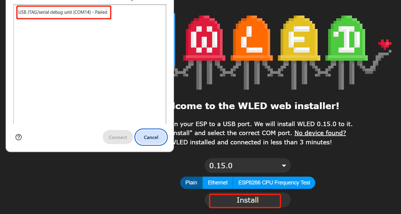
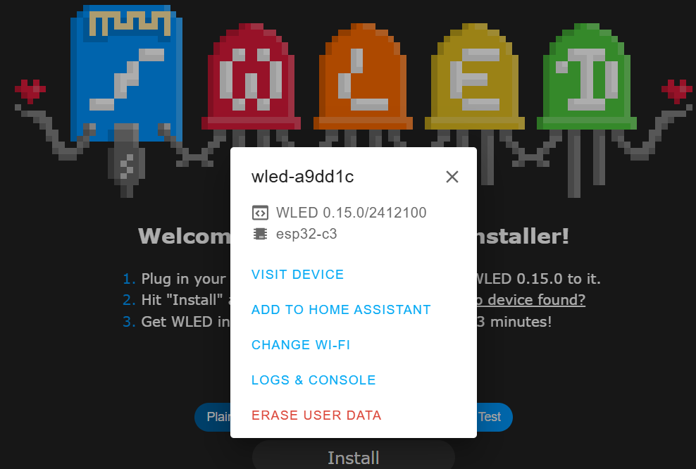
Step 1. Open WLED install web, and connect your XIAO ESP32C3 to your PC, click Install, connect your port.
Step 2. After install successfully,it need you config device wifi, it is recommended to keep your XIAO ESP32C3 and your computer/mobile phone in the same LAN.
Step 3. Now, you can click VISIT DEVICE to control your LED strip.
Step 4. Or you can install WLED App on your phone APP Market, and find your LED device with the + sign in the upper right corner of the software.
If all work well, you can see like this:
Resources
Tech Support & Product Discussion
Thank you for choosing our products! We are here to provide you with different support to ensure that your experience with our products is as smooth as possible. We offer several communication channels to cater to different preferences and needs.