Steering Gear Debugging Tool for SO-ARM in Lerobot
Introduction
The Steering Gear Debugging Tool (Seeed_RoboController) is a graphical debugging tool for Lerobot/SO-ARM robotic arms. With this tool, you can quickly detect servo status, recalibrate servo IDs, write neutral values, control individual servos, and manage robotic arm calibration files, making it easier to assemble, debug, and maintain the leader and follower arms.
1. Installation
For Windows, Ubuntu, and Mac systems.
1. First, clone the repository.
git clone https://github.com/Seeed-Projects/Seeed_RoboController.git
2. It is recommended to install the tool in the Lerobot virtual environment. If you prefer a standalone installation, create a new virtual environment to avoid polluting the system Python.
pip install -r requirements.txt
3. Check the environment. If it returns [OK] Environment check passed, the project is ready to run.
python setup.py
4. Launch the tool.
Run the following command to start interactive port selection.
python -m src.gui.factory_calibration_tool
(Optional) Manually specify ports if they are occupied.
python -m src.gui.factory_calibration_tool --port1 /dev/ttyUSB0 --port2 /dev/ttyUSB1
2. Getting Started (Applicable to Leader Arm and Follower Arm)
1. Check Whether the Servos Are Normal
First, select the corresponding port in the serial port selection.
If servos 1-6 are all detected successfully, it means the servos are recognized normally and the basic functions are working.
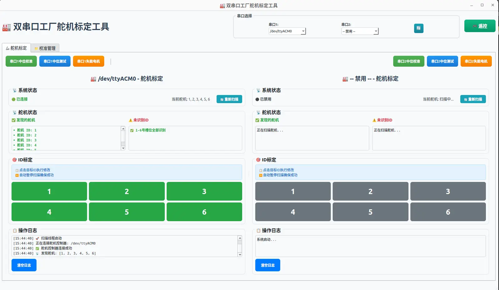
If some servos are shown as not detected, first check whether the wiring is correct, close the page and reopen it. If they are still not detected, the servo IDs may be duplicated (possibly because the command for calibrating the robotic arm was accidentally entered as the command for calibrating the servos). In this case, the IDs of these servos need to be recalibrated.
2. Remove the Servo Wire Harnesses
First remove the connecting wire harness between servo 6 and servo 5.
Then remove the connecting wire harness between servo 5 and servo 4.
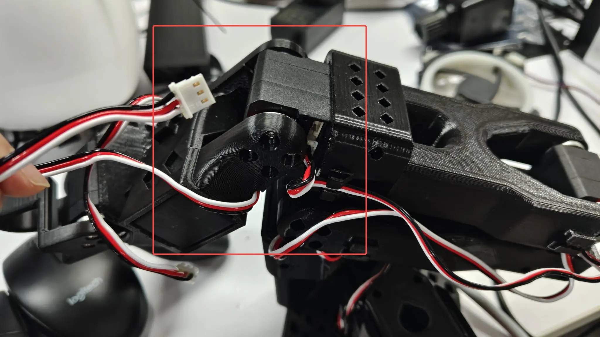
Remove the connecting wire harness between servo 4 and servo 3.
Remove the connecting wire harness between servo 3 and servo 2.
Remove the connecting wire harness between servo 2 and servo 1.
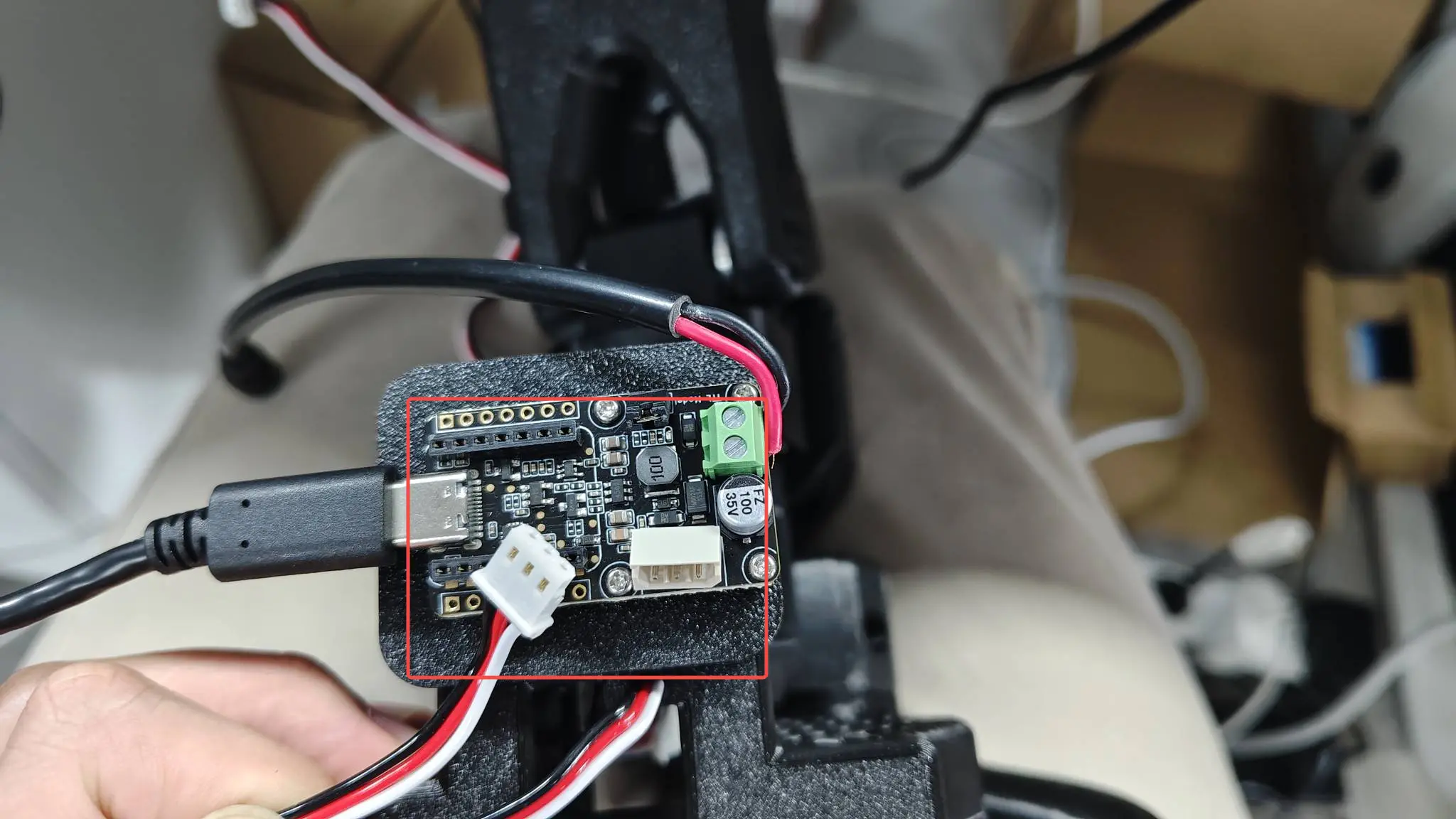
Remove the connecting wire harness between servo 1 and the control board.
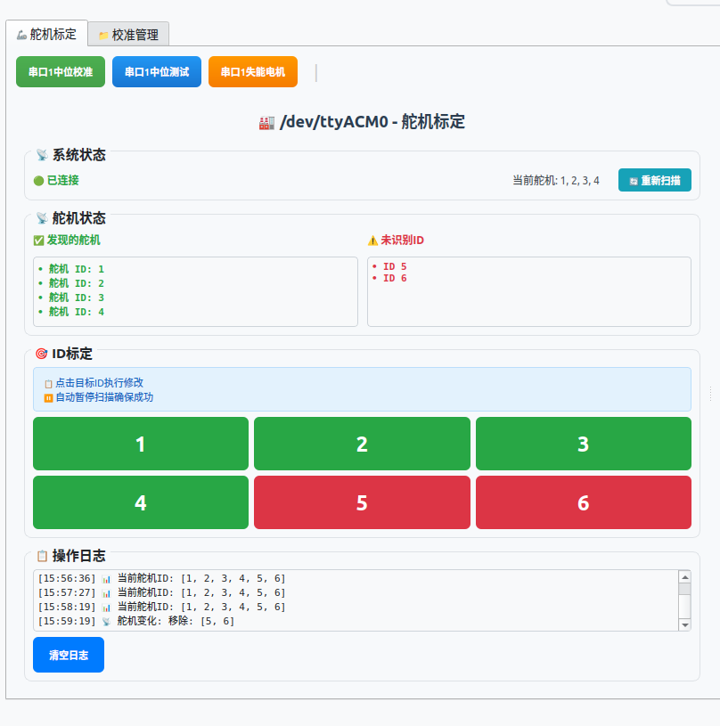
3. Recalibrate Servo IDs
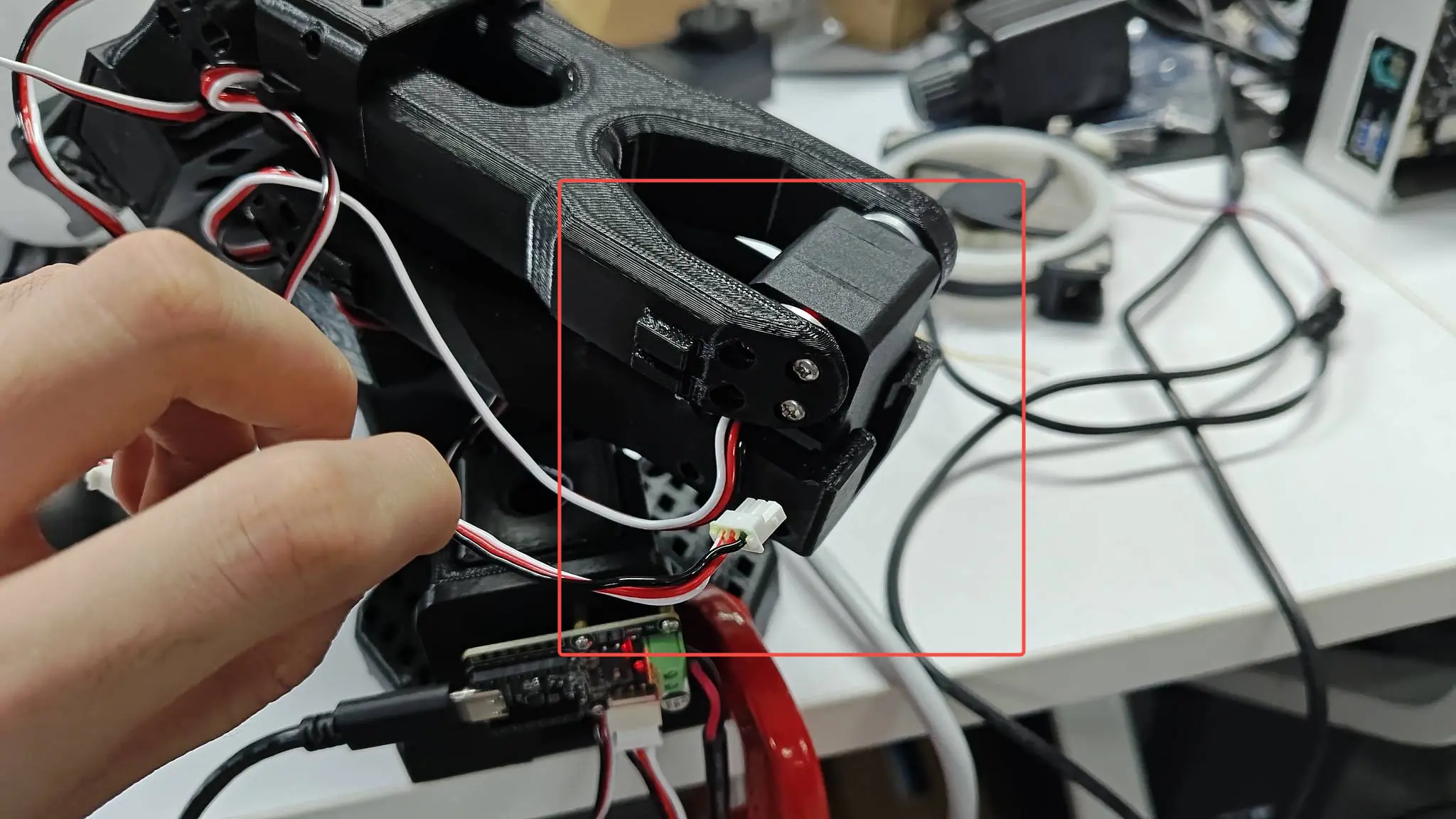
Make sure only one servo is connected to the robotic arm.
(When flashing an ID to a servo, since the servos share a serial bus, if duplicate IDs exist—for example changing ID 4 to 6—all servos with ID 4 on the bus will be changed to 6. Therefore, all servos must be removed and reprogrammed one by one.)
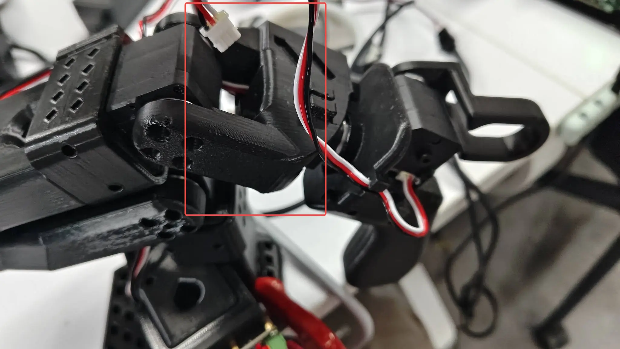
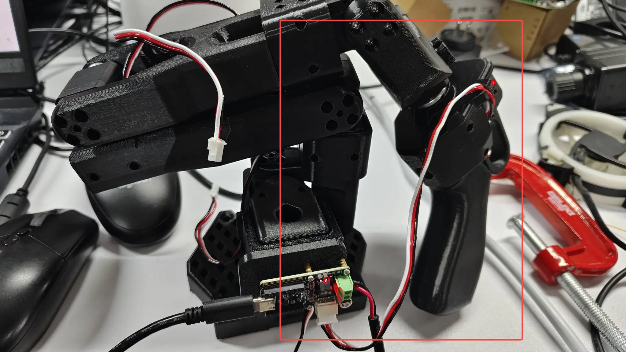
For example, you can connect the #6 servo to the driver board as shown below. Other servos are connected in a similar way, so you can avoid disassembling the robotic arm.
As shown in the figure, only servo #4 is recognized, but the servo actually connected is #6. This indicates that the servo ID is wrong and needs to be changed back to 6.
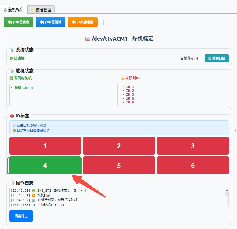
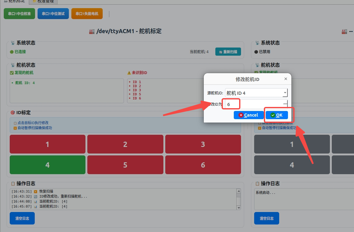
At this point, you can click on servo #4 and change its ID to 6. Repeat the same operation for the other servos.
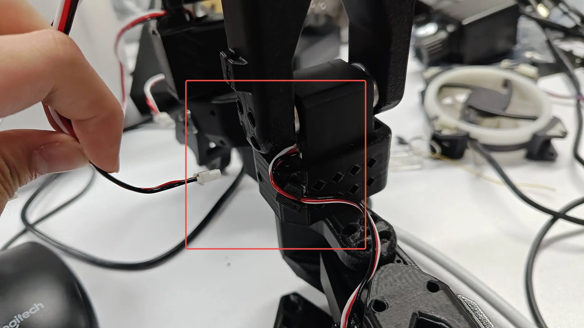
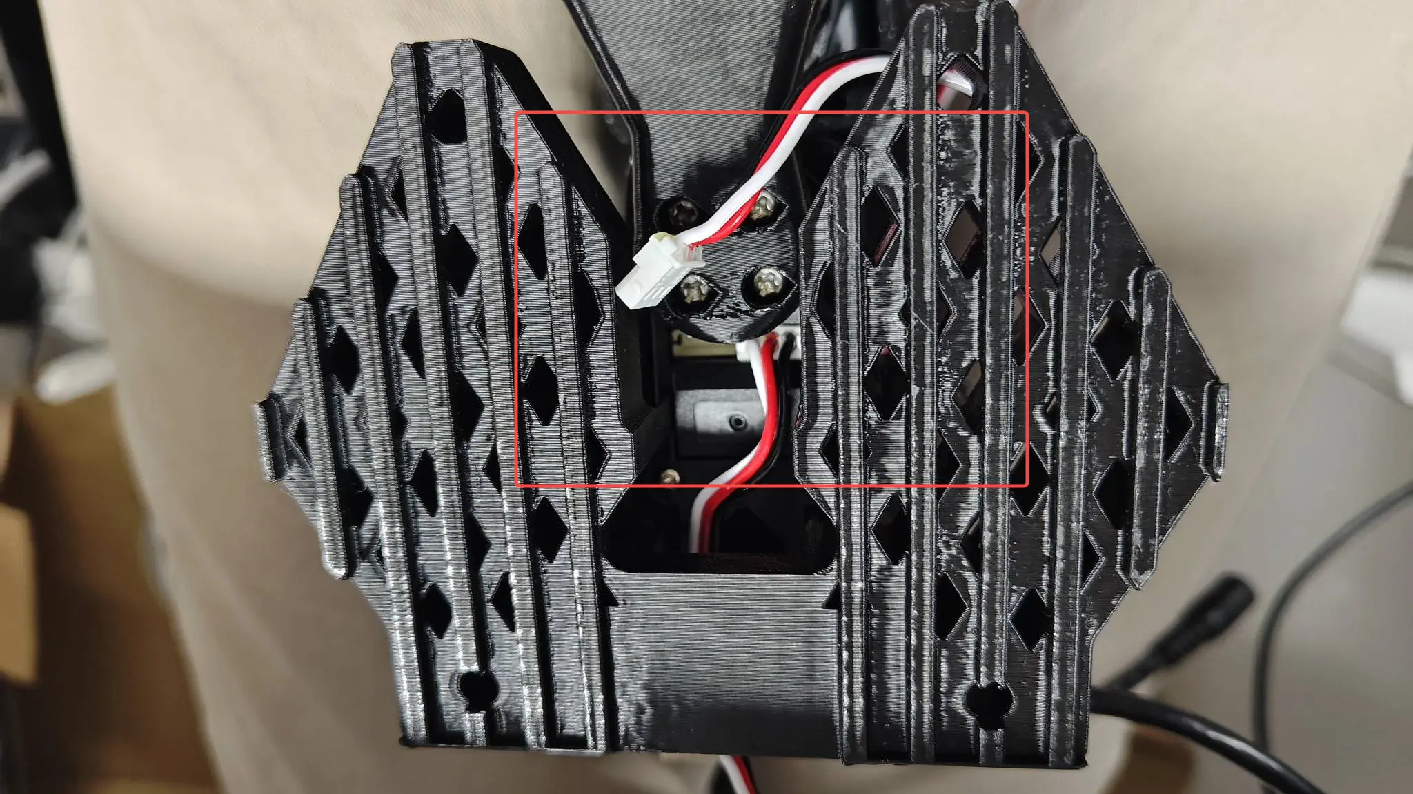
After the servo calibration is complete, you can plug the wires back in one by one to finish.
4. Write the Neutral Value to the Servo

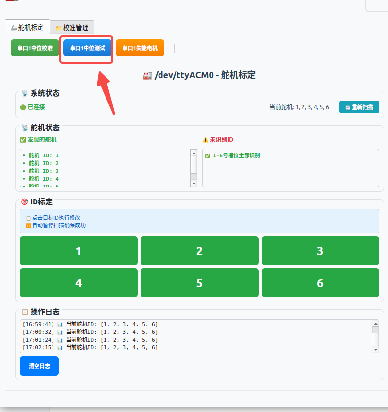
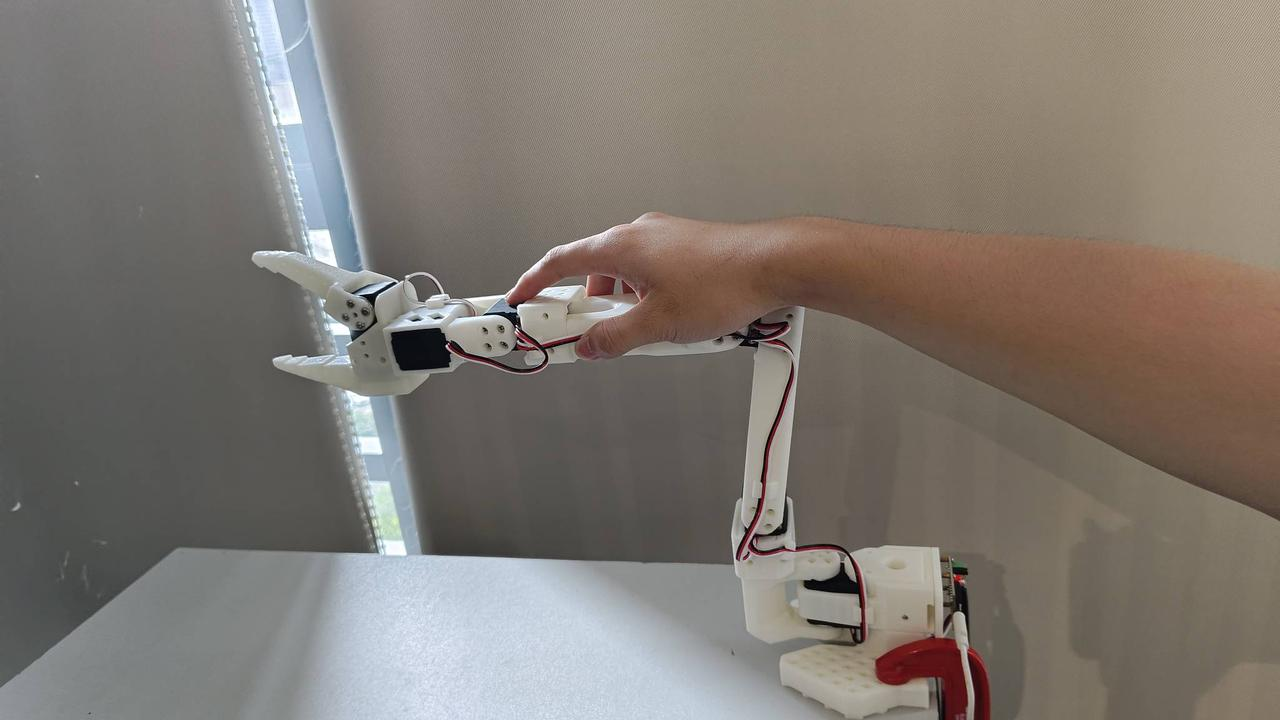
1. Click Serial Port Neutral Test to check whether the robotic arm neutral position is as shown above. If it is roughly the same, the neutral value of the robotic arm is normal.
2. If not, move the robotic arm to the neutral position, then click Serial Port Neutral Calibration. The robotic arm will write the current position as the neutral value into the servo.
3. Click Serial Port Disable Motors, and the robotic arm will go limp; you need to support it by hand.
5. Single Servo Control
By default, all servos on the page are at their neutral positions, as shown in the figure.
-
- First enable torque. You can enable all torques with one click or enable torque for a single servo, then slide the slider to move the servo to the corresponding position. However, be sure to move slowly. Because the printed parts of the robotic arm will physically block certain positions, the arm cannot actually reach the edge positions; there are maximum and minimum movement limits, so do not slide the slider to 0 or to the maximum. After disabling torque, the robotic arm will go limp.
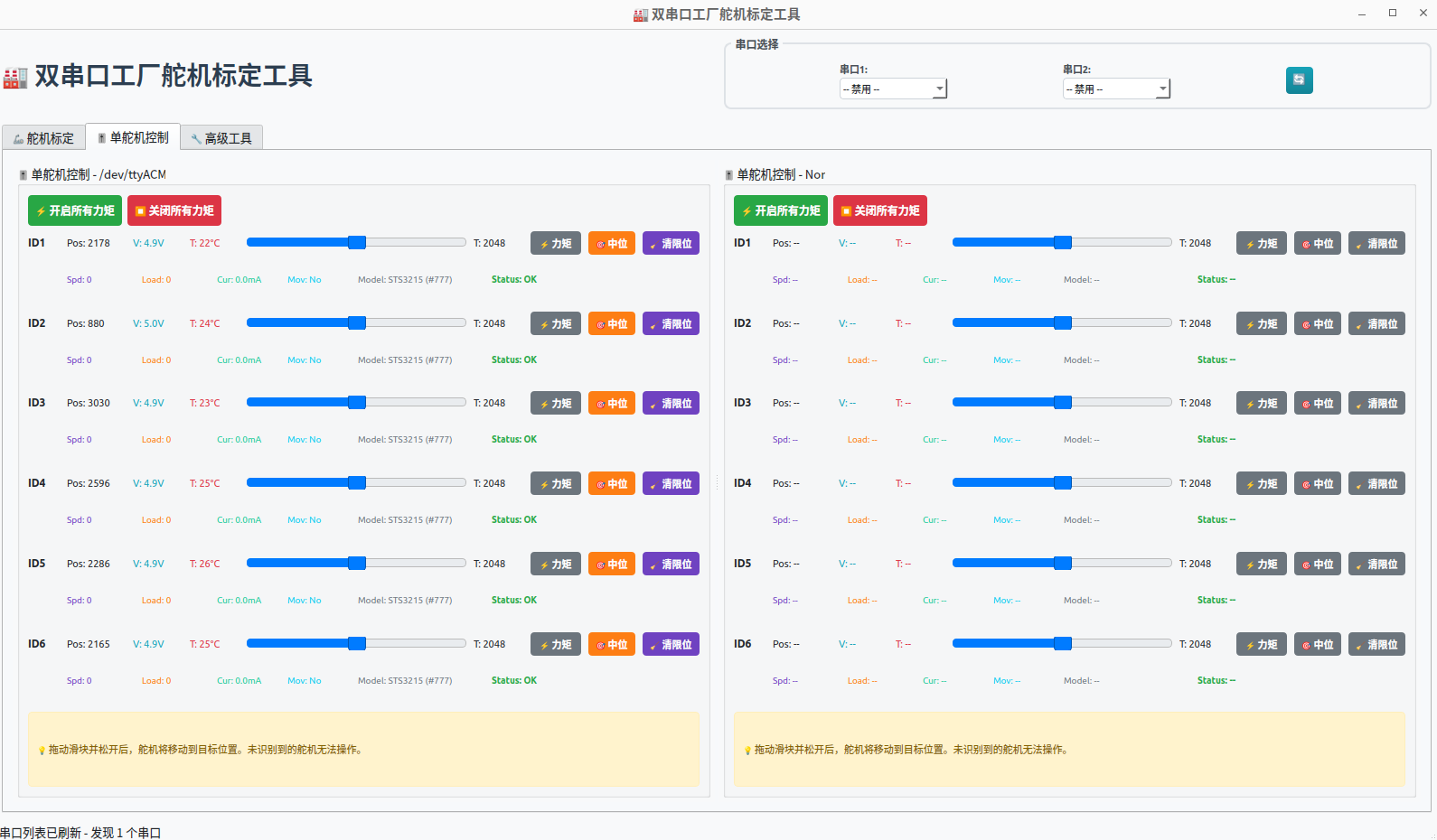
As shown above, after enabling torque, the movement of the corresponding servo will change.
-
- You can perform neutral calibration for a single servo and clear the servo's internal neutral, maximum, and minimum positions
-
- The following is the servo information
Pos: Position
V: Voltage
T: Temperature
Spd: Speed
Load: Torque
Cur: Current
Mov: Motion Status
Model: Model, Authority
Status: Status will show Normal, Overcurrent, or Overload
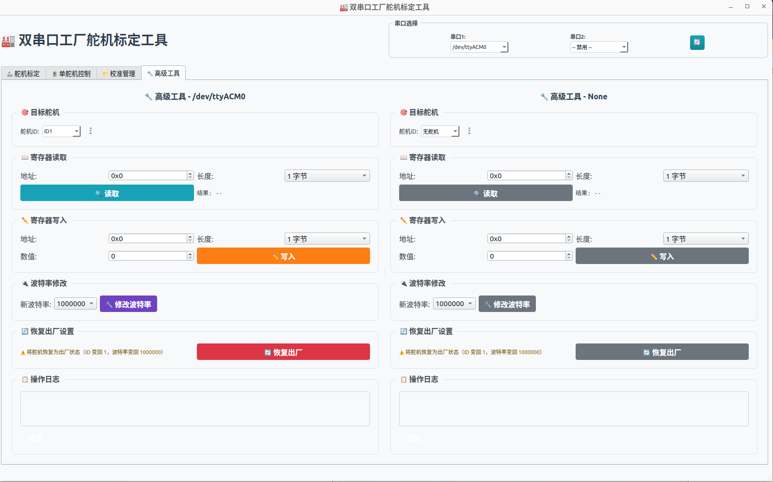
6. Advanced Tools
You can read the corresponding register address data and write the corresponding data.
Baud rate can be modified.
Factory settings can be restored.