Shield CAN BUS FD de 2 canais para Raspberry Pi

Este é um shield CAN BUS para Raspberry Pi (doravante referido como Pi HAT de 2 canais), com E/S CAN BUS de 2 canais, compatível com CAN FD. CAN FD suporta uma velocidade de transmissão muito mais rápida (até 8 Mbps)
Ele também possui dois resistores de terminação de 120Ω on-board que são controlados por chaves.

Declaração de Versões
Existem 3 versões do shield CAN BUS para Raspberry Pi. Todas as 3 versões funcionam perfeitamente na plataforma Raspberry Pi, e você pode pular esta seção se estiver usando a plataforma RPi.
O shield CAN BUS agora só oferece suporte ao Jetson Nano Developer Kit (cartão SD) e não oferece suporte ao Jetson Nano com eMMC (reComputer J1010/J1020v2). Diferentes versões do CAN BUS Shield afetam a funcionalidade, portanto verifique atentamente a tabela abaixo se estiver usando com a plataforma Jetson Nano.
| Nome do Produto | Chip | Estado no RPi | Estado no Jetson Nano |
|---|---|---|---|
| 2-Channel CAN-BUS(FD) Shield for RPi (MCP2517FD) | MCP2517FD | Dois canais | Canal único(can0) |
| 2-Channel CAN-BUS(FD) Shield for Raspberry Pi (MCP2518FD) | MCP2518FD | Dois canais | Dois canais |
Como você pode ver, há duas versões de chips usados no 2-Channel CAN-BUS(FD) Shield for RPi (MCP2517FD) e ambos os canais funcionam no RPi, mas apenas um único canal (CAN0) funciona na plataforma Jetson Nano!
Recursos
- Taxa de transferência em alta velocidade: 8 Mbps@10 m cabo blindado 20AWG / 1 Mbps@40 m cabo blindado 20AWG
- Fonte de alimentação estável, selecionável entre alimentação pelo Raspberry Pi ou fonte DC
- Compatível com Raspberry Pi 2, Raspberry Pi 3, Raspberry Pi 3, Raspberry Pi 4 e Raspberry Pi Zero
- Configuração de um botão para resistor de terminação de 120Ω
- Suporta CAN FD
Visão Geral do Hardware


Guia de Montagem

Você pode ver que usamos colunas de nylon durante a montagem para evitar curto-circuito entre os terminais metálicos sob a porta CAN BUS e a interface HDMI no Raspberry Pi. Portanto, certifique-se de montar a coluna de nylon conforme mostrado.
Especificação
| Parâmetro | Valor |
|---|---|
| Entrada de Alimentação | 12V~24V DC Raspberry Pi GPIO 5V |
| Controlador CAN FD | MCP2517FD |
| Transceptor CAN FD | MCP2557FD |
| Canal CAN FD | 2 |
| Taxa de Transferência | 8 Mbps@10 m cabo blindado 20AWG 1 Mbps@40 m cabo blindado 20AWG |
| Interface de Comunicação com o Pi | SPI |
| Interface Grove | Grove I2C x2 |
Plataformas Compatíveis
| Arduino | Raspberry Pi | |||
|---|---|---|---|---|
Primeiros Passos
Materiais necessários
| Raspberry pi | 2-Channel CAN-BUS(FD) Shield | Placa Arduino | CAN-BUS Shield V2 |
|---|---|---|---|
 |  |  |  |
| Adquira agora | Adquira agora | Adquira agora | Adquira agora |
💡 Nota: O 2 Channel CAN BUS FD Shield for Pi é suportado apenas na versão de kernel 6.6.42 e anteriores.
Também precisamos de dois jumpers macho-macho e cabos de alimentação para energizar essas placas.
Conexão de Hardware
-
Passo 1. Siga o Guia de Montagem para conectar o 2-Channel CAN-BUS(FD) Shield ao Raspberry.
-
Passo 2. Conecte o CAN BUS Shield V2 à placa Seeeduino (ou Arduino)
-
Passo 3. Use os jumpers para conectar o terminal CAN de ambos os shields.
| 2-Channel CAN-BUS(FD) Shield | CAN-BUS Shield V2 |
|---|---|
| CAN_0_L | CANL |
| CAN_0_H | CANH |
Você pode encontrar a serigrafia na parte de trás do shield.
- Passo 4. Alimente o Raspberry Pi e o Seeeduino.

Software
Instalar CAN-HAT
- Passo 1. Abra o arquivo config.txt
sudo nano /boot/config.txt
- Passo 2. Adicione a seguinte linha ao final do arquivo
dtoverlay=seeed-can-fd-hat-v2
-
Passo 3. Pressione Ctrl + x, pressione y e pressione Enter para salvar o arquivo
-
Passo 4. Reinicie o Raspberry Pi
sudo reboot
- Passo 5. Verifique o log do kernel para ver se o CAN-BUS HAT foi inicializado com sucesso. Você também verá can0 e can1 aparecerem na lista de resultados do ifconfig
pi@raspberrypi:~ $ dmesg | grep spi
[    6.178008] mcp25xxfd spi0.0 can0: MCP2517FD rev0.0 (-RX_INT +MAB_NO_WARN +CRC_REG +CRC_RX +CRC_TX +ECC -HD m:20.00MHz r:18.50MHz e:0.00MHz) successfully initialized.
[    6.218466] mcp25xxfd spi0.1 (unnamed net_device) (uninitialized): Failed to detect MCP25xxFD (osc=0x00000000).

pi@raspberrypi:~ $ ifconfig -a
can0: flags=128<NOARP>  mtu 16
        unspec 00-00-00-00-00-00-00-00-00-00-00-00-00-00-00-00  txqueuelen 10  (UNSPEC)
        RX packets 0  bytes 0 (0.0 B)
        RX errors 0  dropped 0  overruns 0  frame 0
        TX packets 0  bytes 0 (0.0 B)
        TX errors 0  dropped 0 overruns 0  carrier 0  collisions 0
        device interrupt 166

can1: flags=128<NOARP>  mtu 16
        unspec 00-00-00-00-00-00-00-00-00-00-00-00-00-00-00-00  txqueuelen 10  (UNSPEC)
        RX packets 0  bytes 0 (0.0 B)
        RX errors 0  dropped 0  overruns 0  frame 0
        TX packets 0  bytes 0 (0.0 B)
        TX errors 0  dropped 0 overruns 0  carrier 0  collisions 0
        device interrupt 167

eth0: flags=4163<UP,BROADCAST,RUNNING,MULTICAST>  mtu 1500
        inet 10.0.0.13  netmask 255.255.255.0  broadcast 10.0.0.255
        inet6 fe80::44cc:eeb8:47a0:7fce  prefixlen 64  scopeid 0x20<link>
        ether b8:27:eb:25:d4:e0  txqueuelen 1000  (Ethernet)
        RX packets 299  bytes 27437 (26.7 KiB)
        RX errors 0  dropped 0  overruns 0  frame 0
        TX packets 172  bytes 25974 (25.3 KiB)
        TX errors 0  dropped 0 overruns 0  carrier 0  collisions 0

lo: flags=73<UP,LOOPBACK,RUNNING>  mtu 65536
        inet 127.0.0.1  netmask 255.0.0.0
        inet6 ::1  prefixlen 128  scopeid 0x10<host>
        loop  txqueuelen 1000  (Local Loopback)
        RX packets 0  bytes 0 (0.0 B)
        RX errors 0  dropped 0  overruns 0  frame 0
        TX packets 0  bytes 0 (0.0 B)
        TX errors 0  dropped 0 overruns 0  carrier 0  collisions 0

wlan0: flags=4098<BROADCAST,MULTICAST>  mtu 1500
        ether b8:27:eb:70:81:b5  txqueuelen 1000  (Ethernet)
        RX packets 0  bytes 0 (0.0 B)
        RX errors 0  dropped 0  overruns 0  frame 0
        TX packets 0  bytes 0 (0.0 B)
        TX errors 0  dropped 0 overruns 0  carrier 0  collisions 0
- Passo 6. Defina o protocolo CAN FD, e o
dbitratepode ser definido para velocidade de 8M. Consulte a documentação do kernel para mais usos
sudo ip link set can0 up type can bitrate 1000000   dbitrate 8000000 restart-ms 1000 berr-reporting on fd on
sudo ip link set can1 up type can bitrate 1000000   dbitrate 8000000 restart-ms 1000 berr-reporting on fd on

sudo ifconfig can0 txqueuelen 65536
sudo ifconfig can1 txqueuelen 65536
- Passo 7. Abra duas janelas de terminal e insira os seguintes comandos nas janelas para testar o protocolo CAN FD.
#send data
cangen can0 -mv
#dump data
candump can0
Você pode testar o CAN-BUS conectando dois canais entre si usando jumpers: 0_L <===> 1_L, 0_H <===> 1_H.
Comunicação com Arduino CAN BUS Shield
Neste demo, usamos apenas um dos dois canais.
Para o Arduino CAN BUS Shield, fornecemos o código Arduino; se você não souber como usar o Arduino, por favor verifique aqui.
Para o pi hat de 2 canais, há duas maneiras de enviar e receber; você pode usar tanto can-util/cangen quanto código em Python.
CAN BUS Shield envia e CAN HAT recebe
Código Arduino para CAN BUS Shield:
// demo: CAN-BUS Shield, send data
// [email protected]

#include <mcp_can.h>
#include <SPI.h>

// the cs pin of the version after v1.1 is default to D9
// v0.9b and v1.0 is default D10
const int SPI_CS_PIN = 9;

MCP_CAN CAN(SPI_CS_PIN);                                    // Set CS pin

void setup()
{
    Serial.begin(115200);

    while (CAN_OK != CAN.begin(CAN_500KBPS))              // init can bus : baudrate = 500k
    {
        Serial.println("CAN BUS Shield init fail");
        Serial.println(" Init CAN BUS Shield again");
        delay(100);
    }
    Serial.println("CAN BUS Shield init ok!");
}

unsigned char stmp[8] = {0, 0, 0, 0, 0, 0, 0, 0};
void loop()
{
    //send data:  id = 0x00, standrad frame, data len = 8, stmp: data buf
    stmp[7] = stmp[7]+1;
    if(stmp[7] == 100)
    {
        stmp[7] = 0;
        stmp[6] = stmp[6] + 1;

        if(stmp[6] == 100)
        {
            stmp[6] = 0;
            stmp[5] = stmp[6] + 1;
        }
    }

    CAN.sendMsgBuf(0x00, 0, 8, stmp);
    delay(100);                       // send data per 100ms
}
// END FILE
Configuração do Raspberry Pi e você pode usar can-util para receber
#set 500k baudrate
pi@raspberrypi:~ $ sudo ip link set can0 up type can bitrate 500000
pi@raspberrypi:~ $ ip -details link show can0
3: can0: <NOARP,UP,LOWER_UP,ECHO> mtu 16 qdisc pfifo_fast state UNKNOWN mode DEFAULT group default qlen 10
    link/can  promiscuity 0
    can state ERROR-ACTIVE (berr-counter tx 0 rx 0) restart-ms 0
   bitrate 500000 sample-point 0.875
   tq 25 prop-seg 34 phase-seg1 35 phase-seg2 10 sjw 1
   mcp25xxfd: tseg1 2..256 tseg2 1..128 sjw 1..128 brp 1..256 brp-inc 1
   mcp25xxfd: dtseg1 1..32 dtseg2 1..16 dsjw 1..16 dbrp 1..256 dbrp-inc 1
   clock 40000000numtxqueues 1 numrxqueues 1 gso_max_size 65536 gso_max_segs 65535
#receive
pi@raspberrypi:~ $ candump can0
  can0  000   [8]  00 00 00 00 00 00 00 05
  can0  000   [8]  00 00 00 00 00 00 00 06
  can0  000   [8]  00 00 00 00 00 00 00 07
  can0  000   [8]  00 00 00 00 00 00 00 08
  can0  000   [8]  00 00 00 00 00 00 00 09
  can0  000   [8]  00 00 00 00 00 00 00 0A
  can0  000   [8]  00 00 00 00 00 00 00 0B
  can0  000   [8]  00 00 00 00 00 00 00 0C
  can0  000   [8]  00 00 00 00 00 00 00 0D
  can0  000   [8]  00 00 00 00 00 00 00 0E
  can0  000   [8]  00 00 00 00 00 00 00 0F
  can0  000   [8]  00 00 00 00 00 00 00 10
  can0  000   [8]  00 00 00 00 00 00 00 11
  can0  000   [8]  00 00 00 00 00 00 00 12
  can0  000   [8]  00 00 00 00 00 00 00 13
  can0  000   [8]  00 00 00 00 00 00 00 14
  can0  000   [8]  00 00 00 00 00 00 00 15
  can0  000   [8]  00 00 00 00 00 00 00 16
  can0  000   [8]  00 00 00 00 00 00 00 17
  can0  000   [8]  00 00 00 00 00 00 00 18
  can0  000   [8]  00 00 00 00 00 00 00 19
  can0  000   [8]  00 00 00 00 00 00 00 1A
  can0  000   [8]  00 00 00 00 00 00 00 1B
  can0  000   [8]  00 00 00 00 00 00 00 1C
  can0  000   [8]  00 00 00 00 00 00 00 1D
Ou você pode usar código em Python para obter os dados CAN. Para usar Python para receber dados CAN, você deve instalar o python-can primeiro.
# install python-can
sudo pip3 install python-can
Abra um novo arquivo Python e copie o seguinte código, salve como can_test.py:
import can

can_interface = 'can0'
bus = can.interface.Bus(can_interface, bustype='socketcan_native')
while True:
    message = bus.recv(1.0) # Timeout in seconds.
    if message is None:
            print('Timeout occurred, no message.')
    print(message)
Execute o código Python e os resultados são os seguintes:
pi@raspberrypi:~ $ python3 can_test.py
Timestamp: 1550471771.628215        ID: 0000    S                DLC:  8    00 00 00 00 00 00 0e 63     Channel: can0
Timestamp: 1550471772.629302        ID: 0000    S                DLC:  8    00 00 00 00 00 00 0f 00     Channel: can0
Timestamp: 1550471773.630658        ID: 0000    S                DLC:  8    00 00 00 00 00 00 0f 01     Channel: can0
Timestamp: 1550471774.632018        ID: 0000    S                DLC:  8    00 00 00 00 00 00 0f 02     Channel: can0
Timestamp: 1550471775.633395        ID: 0000    S                DLC:  8    00 00 00 00 00 00 0f 03     Channel: can0
Timestamp: 1550471776.634774        ID: 0000    S                DLC:  8    00 00 00 00 00 00 0f 04     Channel: can0
Timestamp: 1550471777.636135        ID: 0000    S                DLC:  8    00 00 00 00 00 00 0f 05     Channel: can0
Timestamp: 1550471778.637481        ID: 0000    S                DLC:  8    00 00 00 00 00 00 0f 06     Channel: can0
Timestamp: 1550471779.638859        ID: 0000    S                DLC:  8    00 00 00 00 00 00 0f 07     Channel: can0
Timestamp: 1550471780.640222        ID: 0000    S                DLC:  8    00 00 00 00 00 00 0f 08     Channel: can0
Timestamp: 1550471781.641602        ID: 0000    S                DLC:  8    00 00 00 00 00 00 0f 09     Channel: can0
Timestamp: 1550471782.642970        ID: 0000    S                DLC:  8    00 00 00 00 00 00 0f 0a     Channel: can0
CAN BUS Shield recebe e CAN HAT envia
Para o Raspberry Pi, você pode usar cangen para enviar pacotes aleatórios:
pi@raspberrypi:~ $ cangen can0 -v
  can0  442#14.C4.1A.1A.C2.25.79.25
  can0  748#4E.C7.8B.0B.6E.B9.15.77
  can0  1E4#64.D4.62.22.2F.A6.BF
  can0  1DD#69.6F.61.33.1F.59.E4.7C
  can0  63D#
  can0  764#2C.C1.E3
  can0  68B#11.9C.63.6D.EA.E9.4B
  can0  329#DA.06.2C.34.6C
  can0  7DD#2E.F5.E0.2A.26.77.58.38
  can0  1BE#94.30.6E.2F.A2.7B.E3.1D
  can0  654#D1.21.A3.58.31.E8.51.5F
  can0  706#51.41.36.5C.43.8D.AE.5D
  can0  34A#89.F2.DE.33.AE.52.38.6C
  can0  6AC#C1.35.83.41.37
  can0  38C#22.AF
  can0  208#22.8E.97.58.E5.69.F7.2C
Para Arduino, você pode usar o seguinte código para receber dados CAN.
// demo: CAN-BUS Shield, receive data with interrupt mode
// when in interrupt mode, the data coming can't be too fast, must >20ms, or else you can use check mode
// loovee, 2014-6-13

#include <SPI.h>
#include "mcp_can.h"

// the cs pin of the version after v1.1 is default to D9
// v0.9b and v1.0 is default D10
const int SPI_CS_PIN = 9;

MCP_CAN CAN(SPI_CS_PIN);                                    // Set CS pin


unsigned char flagRecv = 0;
unsigned char len = 0;
unsigned char buf[8];
char str[20];

void setup()
{
    Serial.begin(115200);

    while (CAN_OK != CAN.begin(CAN_500KBPS))              // init can bus : baudrate = 500k
    {
        Serial.println("CAN BUS Shield init fail");
        Serial.println(" Init CAN BUS Shield again");
        delay(100);
    }
    Serial.println("CAN BUS Shield init ok!");

    attachInterrupt(0, MCP2515_ISR, FALLING); // start interrupt
}

void MCP2515_ISR()
{
    flagRecv = 1;
}

void loop()
{
    if(flagRecv)
    {                                   // check if get data

        flagRecv = 0;                   // clear flag

        // iterate over all pending messages
        // If either the bus is saturated or the MCU is busy,
        // both RX buffers may be in use and reading a single
        // message does not clear the IRQ conditon.
        while (CAN_MSGAVAIL == CAN.checkReceive())
        {
            // read data,  len: data length, buf: data buf
            CAN.readMsgBuf(&len, buf);

            // print the data
            for(int i = 0; i<len; i++)
            {
                Serial.print(buf[i]);Serial.print("\t");
            }
            Serial.println();
        }
    }
}
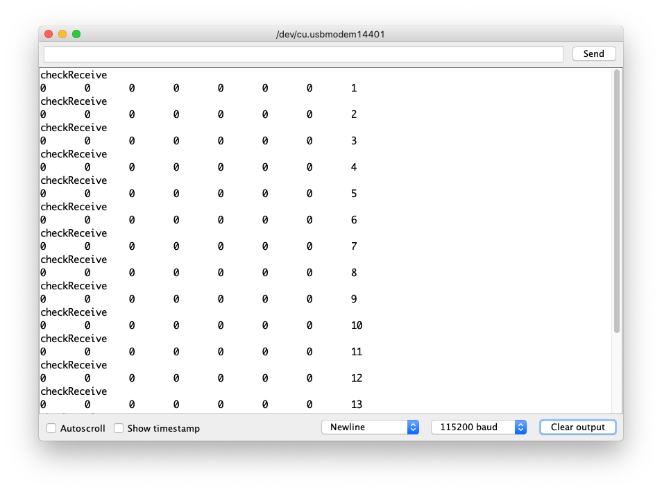
Abra o Serial Monitor da Arduino IDE clicando em Tool-> Serial Monitor. Ou pressione as teclas ctrl+shift+m ao mesmo tempo. Defina a taxa de baud para 115200. O resultado deve ser como:

Ou você pode usar python-can para enviar dados:
O código Python é o seguinte:
import time
import can

bustype = 'socketcan_native'
channel = 'can0'

def producer(id):
    """:param id: Spam the bus with messages including the data id."""
    bus = can.interface.Bus(channel=channel, bustype=bustype)
    for i in range(10):
        msg = can.Message(arbitration_id=0xc0ffee, data=[id, i, 0, 1, 3, 1, 4, 1], extended_id=False)
        bus.send(msg)
    # Issue #3: Need to keep running to ensure the writing threads stay alive. ?
    time.sleep(1)

producer(10)
desinstalar CAN-HAT
Se você quiser desinstalar este CAN-HAT, basta executar o seguinte código:
pi@raspberrypi:~/seeed-linux-dtoverlays/modules/CAN-HAT $ sudo ./uninstall.sh
...
------------------------------------------------------
Please reboot your raspberry pi to apply all settings
Thank you!
------------------------------------------------------
Usando CAN-BUS Shiled com Jetson Nano
Agora o CAN-BUS Shiled também suporta a plataforma Jetson Nano, mas há algumas limitações baseadas em diferentes versões de hardware. Consulte a Declaração de Versão se você estiver usando a plataforma Jetson Nano!
- Clone the Repo:
git clone https://github.com/Seeed-Studio/seeed-linux-dtoverlays
- Compile dtbo e driver:
cd seeed-linux-dtoverlays
export CUSTOM_MOD_LIST="CAN-HAT"; make all_jetsonnano
- Instalar o Driver:
sudo -E make install_jetsonnano
- Instalar dtbo:
sudo cp overlays/jetsonnano/2xMCP2518FD-spi0.dtbo /boot
sudo /opt/nvidia/jetson-io/config-by-hardware.py -n "Seeed 2xMCP2518FD"
sudo reboot
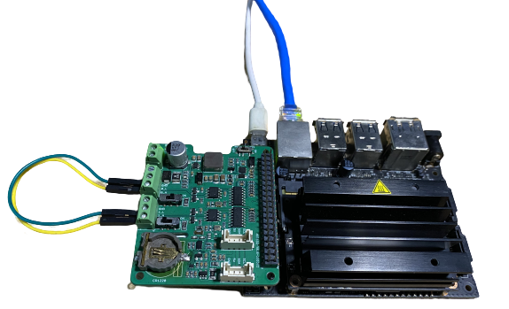
Agora você também pode executar dmesg | grep spi e ifconfig -a para verificar se o CAN-BUS foi inicializado corretamente. Dependendo do seu hardware, você deverá conseguir ver can0 ou tanto can0 quanto can1.
O hardware usado aqui é o mais recente 2-Channel CAN FD Master Hat para RPi, que suporta dois canais na plataforma Jetson Nano; se você tiver versões mais antigas, então terá apenas um único canal can0.
qqq@jetson-qqq:~$ dmesg | grep spi
[   10.867712] mcp25xxfd spi0.0 can0: MCP2518FD rev0.0 (-RX_INT -MAB_NO_WARN +CRC_REG +CRC_RX +CRC_TX +ECC -HD m:20.00MHz r:18.50MHz e:0.00MHz) successfully initialized.
[   10.879487] mcp25xxfd spi0.1 can1: MCP2518FD rev0.0 (-RX_INT -MAB_NO_WARN +CRC_REG +CRC_RX +CRC_TX +ECC -HD m:20.00MHz r:18.50MHz e:0.00MHz) successfully initialized.

qqq@jetson-qqq:~$ ifconfig -a
can0: flags=128<NOARP>  mtu 16
        unspec 00-00-00-00-00-00-00-00-00-00-00-00-00-00-00-00  txqueuelen 10  (UNSPEC)
        RX packets 0  bytes 0 (0.0 B)
        RX errors 0  dropped 0  overruns 0  frame 0
        TX packets 0  bytes 0 (0.0 B)
        TX errors 0  dropped 0 overruns 0  carrier 0  collisions 0
        device interrupt 112

can1: flags=128<NOARP>  mtu 16
        unspec 00-00-00-00-00-00-00-00-00-00-00-00-00-00-00-00  txqueuelen 10  (UNSPEC)
        RX packets 0  bytes 0 (0.0 B)
        RX errors 0  dropped 0  overruns 0  frame 0
        TX packets 0  bytes 0 (0.0 B)
        TX errors 0  dropped 0 overruns 0  carrier 0  collisions 0
        device interrupt 114
Teste
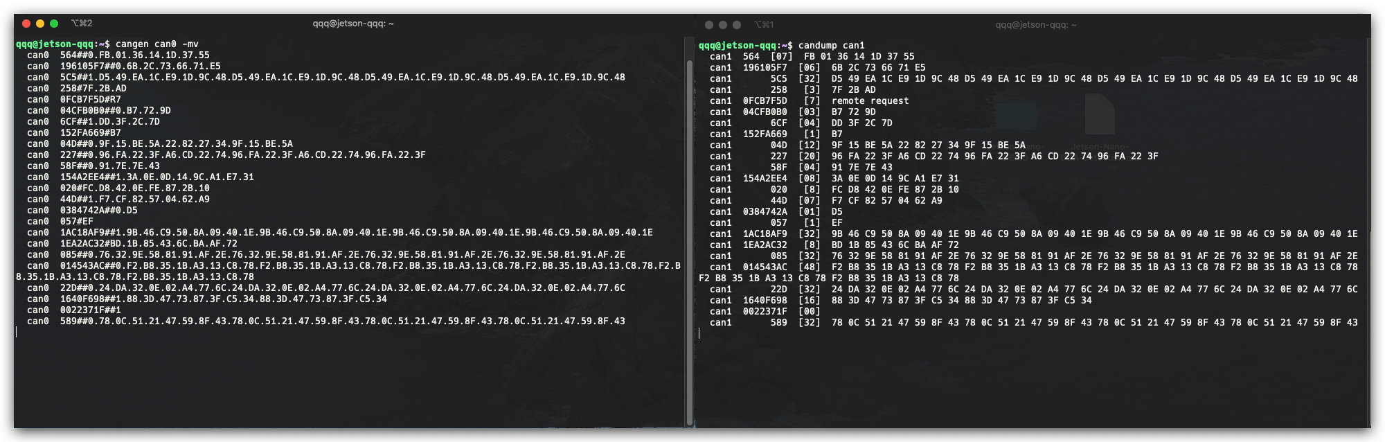
NOTE: Usando o 2-Channel CAN FD Master Hat para RPi como hardware aqui.
Você também pode conectar os canais da seguinte forma para testar:
0_L <===> 1_L
0_H <===> 1_H
Abra duas janelas de terminal e insira os seguintes comandos nas janelas para testar o protocolo CAN FD.
#send data
cangen can0 -mv
#dump data
candump can1
Uso do RTC Integrado
O mais recente 2-Channel CAN FD Master Hat para RPi também possui um RTC on-board. Siga adiante para instalar os drivers RTC no Raspberry Pi:
- Atualize o Raspberry Pi e reinicie:
sudo apt update
sudo apt upgrade
sudo reboot
- Instalar Dependências
sudo apt install i2c-tools build-essential raspberrypi-kernel-headers
- Baixar o driver:
curl -O -L https://github.com/dresden-elektronik/raspbee2-rtc/archive/master.zip
unzip master.zip
- Compilar o módulo do Kernel RTC
cd raspbee2-rtc-master
make
- Instalar o módulo do Kernel RTC
sudo make install
sudo reboot
- Configurar a hora do sistema para o módulo RTC
sudo hwclock --systohc
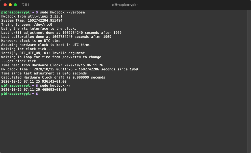
- Testar se o RTC está funcionando
sudo hwclock --verbose
Agora você pode ler a hora do RTC usando o seguinte comando:
sudo hwclock -r
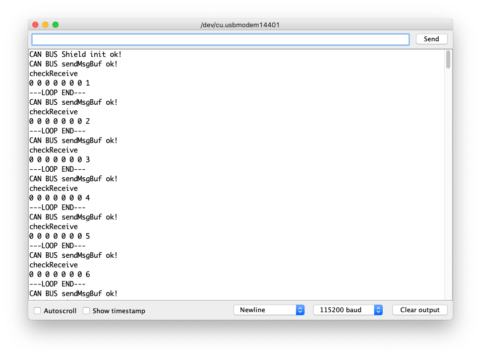
Usando com Wio Terminal
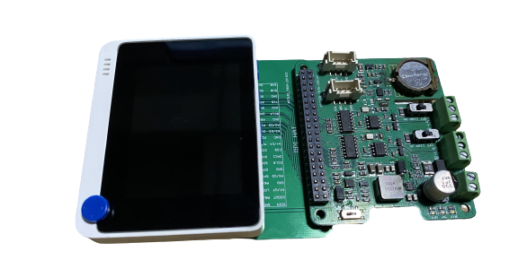
Além de usar o CAN-BUS Pi Hat com SBCs, agora você também pode usá-lo com o Wio Terminal (Placa Compatível com Arduino)! E desenvolver projetos relacionados a CAN em MCU!
Por favor, consulte os seguintes wikis para saber mais sobre o Wio Terminal:
Hardware Necessário
Para fins de teste, você também pode preparar alguns outros componentes de desenvolvimento CAN-BUS; para este exemplo estamos usando o seguinte:
- CAN-BUS Shield V2 com MCP2515 e MCP2551 + Placa Arduino
Instalar a Biblioteca Arduino Seeed_Arduino_CAN
Certifique-se de que você instalou a biblioteca Seeed SAMD Board e a atualizou para a versão mais recente!
-
Visite o repositório Seeed_Arduino_CAN e baixe todo o repositório para o seu disco local.
-
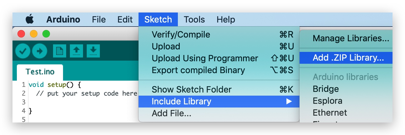
Agora, a biblioteca Seeed_Arduino_CAN pode ser instalada na Arduino IDE. Abra a Arduino IDE e clique em
sketch->Include Library->Add .ZIP Library, e escolha o arquivoSeeed_Arduino_CANque você acabou de baixar.
Código de Exemplo de Envio
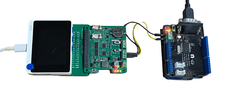
Este é um exemplo de uso do 2-Channel CAN-BUS(FD) Shield for Raspberry Pi (MCP2518FD) com Wio Terminal para enviar dados CAN-BUS para outro dispositivo CAN-BUS (neste caso, é o CAN-BUS Shield V2 com MCP2515 e MCP2551 + Arduino Uno)
Conexão de Hardware
-
Conecte
Channel 0 Ldo 2-Channel CAN-BUS(FD) Shield for Raspberry Pi (MCP2518FD) ->CANLdo CAN-BUS Shield V2 -
Conecte
Channel 0 Hdo 2-Channel CAN-BUS(FD) Shield for Raspberry Pi (MCP2518FD) ->CANHdo CAN-BUS Shield V2 -
Conecte o 2-Channel CAN-BUS(FD) Shield for Raspberry Pi (MCP2518FD) ao Wio Terminal usando a Placa Adaptadora Hat Raspberry Pi de 40 Pinos para Wio Terminal.
- Código para Arduino Uno + CAN-BUS Shield V2
#include <SPI.h>
#include "mcp2515_can.h"

/*SAMD core*/
#ifdef ARDUINO_SAMD_VARIANT_COMPLIANCE
    #define SERIAL SerialUSB
#else
    #define SERIAL Serial
#endif

const int SPI_CS_PIN = 9;
mcp2515_can CAN(SPI_CS_PIN);

unsigned char len = 0;
unsigned char buf[8];

void setup() {
    SERIAL.begin(115200);
    while (!SERIAL) {
        ; // wait for serial port to connect. Needed for native USB port only
    }
    while (CAN_OK != CAN.begin(CAN_500KBPS)) {             // init can bus : baudrate = 500k
        // init can bus : baudrate = 500k
        SERIAL.println("CAN BUS Shield init fail");
        SERIAL.println(" Init CAN BUS Shield again");
        delay(100);
    }
    SERIAL.println("CAN BUS Shield init ok!");
}

void loop() {
        // iterate over all pending messages
        // If either the bus is saturated or the MCU is busy,
        // both RX buffers may be in use and reading a single
        // message does not clear the IRQ conditon.
        while (CAN_MSGAVAIL == CAN.checkReceive()) {
            // read data,  len: data length, buf: data buf
            SERIAL.println("checkReceive");
            CAN.readMsgBuf(&len, buf);

            // print the data
            for (int i = 0; i < len; i++) {
                SERIAL.print(buf[i]); SERIAL.print("\t");
            }
            SERIAL.println();
        }
}
- Código para Wio Terminal + 2-Channel CAN-BUS(FD) Shield for Raspberry Pi (MCP2518FD)
#include <SPI.h>
#include "mcp2518fd_can.h"
/*SAMD core*/
#ifdef ARDUINO_SAMD_VARIANT_COMPLIANCE
#define SERIAL SerialUSB
#else
#define SERIAL Serial
#endif
// Set SPI CS Pin according to your hardware
// For Wio Terminal w/ MCP2518FD RPi Hat:
// Channel 0 SPI_CS Pin: BCM 8
// Channel 1 SPI_CS Pin: BCM 7
// Interupt Pin: BCM25
// *****************************************
// For Arduino MCP2515 Hat:
// SPI_CS Pin: D9
const int SPI_CS_PIN = BCM8;
mcp2518fd CAN(SPI_CS_PIN); // Set CS pin
void setup() {
SERIAL.begin(115200);
while(!Serial){};
while (0 != CAN.begin((byte)CAN_500K_1M)) { // init can bus : baudrate = 500k
SERIAL.println("CAN BUS Shield init fail");
SERIAL.println(" Init CAN BUS Shield again");
delay(100);
}
SERIAL.println("CAN BUS Shield init ok!");
}
unsigned char stmp[8] = {0, 0, 0, 0, 0, 0, 0, 0};
void loop() {
// send data: id = 0x00, standrad frame, data len = 8, stmp: data buf
stmp[7] = stmp[7] + 1;
if (stmp[7] == 100) {
stmp[7] = 0;
stmp[6] = stmp[6] + 1;
if (stmp[6] == 100) {
stmp[6] = 0;
stmp[5] = stmp[6] + 1;
}
}
CAN.sendMsgBuf(0x00, 0, 8, stmp);
delay(100); // send data per 100ms
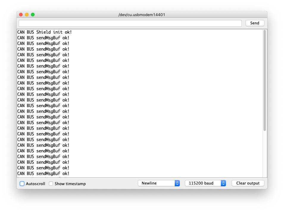
SERIAL.println("CAN BUS sendMsgBuf ok!");
}
Código de Exemplo de Recepção
Este é um exemplo de uso do 2-Channel CAN-BUS(FD) Shield for Raspberry Pi (MCP2518FD) com Wio Terminal para receber dados CAN-BUS de outro dispositivo CAN-BUS (neste caso, é o CAN-BUS Shield V2 com MCP2515 e MCP2551 + Arduino Uno)
Conexão de Hardware
Mesma conexão do Exemplo de Envio acima.
- Código para Arduino Uno + CAN-BUS Shield V2
#include <SPI.h>
#include "mcp2515_can.h"

/*SAMD core*/
#ifdef ARDUINO_SAMD_VARIANT_COMPLIANCE
    #define SERIAL SerialUSB
#else
    #define SERIAL Serial
#endif

const int SPI_CS_PIN = 9;
mcp2515_can CAN(SPI_CS_PIN); // Set CS pin


void setup() {
    SERIAL.begin(115200);
    while(!Serial){};

    while (CAN_OK != CAN.begin(CAN_500KBPS)) {             // init can bus : baudrate = 500k
        SERIAL.println("CAN BUS Shield init fail");
        SERIAL.println(" Init CAN BUS Shield again");
        delay(100);
    }
    SERIAL.println("CAN BUS Shield init ok!");
}

unsigned char stmp[8] = {0, 0, 0, 0, 0, 0, 0, 0};
void loop() {
    // send data:  id = 0x00, standrad frame, data len = 8, stmp: data buf
    stmp[7] = stmp[7] + 1;
    if (stmp[7] == 100) {
        stmp[7] = 0;
        stmp[6] = stmp[6] + 1;

        if (stmp[6] == 100) {
            stmp[6] = 0;
            stmp[5] = stmp[6] + 1;
        }
    }

    CAN.sendMsgBuf(0x00, 0, 8, stmp);
    delay(100);                       // send data per 100ms
    SERIAL.println("CAN BUS sendMsgBuf ok!");
}
- Código para Wio Terminal + Shield CAN-BUS(FD) de 2 canais para Raspberry Pi (MCP2518FD)
#include <SPI.h>
#include "mcp2518fd_can.h"

/*SAMD core*/
#ifdef ARDUINO_SAMD_VARIANT_COMPLIANCE
    #define SERIAL SerialUSB
#else
    #define SERIAL Serial
#endif

// Set SPI CS Pin according to your hardware
// For Wio Terminal w/ MCP2518FD RPi Hat:
// Channel 0 SPI_CS Pin: BCM 8
// Channel 1 SPI_CS Pin: BCM 7
// Interupt Pin: BCM25
// *****************************************
// For Arduino MCP2515 Hat:
// SPI_CS Pin: D9

const int SPI_CS_PIN = BCM8;
mcp2518fd CAN(SPI_CS_PIN);

unsigned char len = 0;
unsigned char buf[8];

void setup() {
    SERIAL.begin(115200);
    while (!SERIAL) {
        ; // wait for serial port to connect. Needed for native USB port only
    }
    while (0 != CAN.begin((byte)CAN_500K_1M)) {            // init can bus : baudrate = 500k
        SERIAL.println("CAN BUS Shield init fail");
        SERIAL.println(" Init CAN BUS Shield again");
        delay(100);
    }
    SERIAL.println("CAN BUS Shield init ok!");
}

void loop() {
        // iterate over all pending messages
        // If either the bus is saturated or the MCU is busy,
        // both RX buffers may be in use and reading a single
        // message does not clear the IRQ conditon.
        while (CAN_MSGAVAIL == CAN.checkReceive()) {
            // read data,  len: data length, buf: data buf
            SERIAL.println("checkReceive");
            CAN.readMsgBuf(&len, buf);

            // print the data
            for (int i = 0; i < len; i++) {
                SERIAL.print(buf[i]); SERIAL.print("\t");
            }
            SERIAL.println();
        }
}
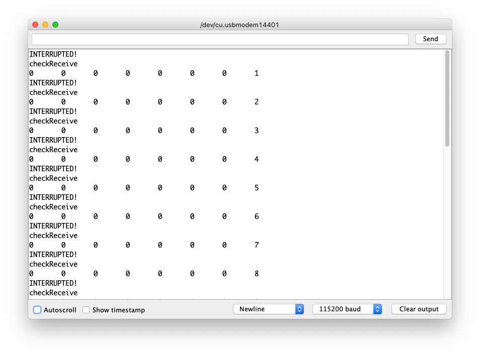
Exemplo de código de recepção usando interrupção
Este é um exemplo de uso do Shield CAN-BUS(FD) de 2 canais para Raspberry Pi (MCP2518FD) com Wio Terminal para receber dados CAN-BUS de outro dispositivo CAN-BUS (neste caso, é o CAN-BUS Shield V2 que adota MCP2515 e MCP2551 + Arduino Uno). Para torná‑lo mais confiável, aqui é usada uma interrupção para acionar o fluxo de dados de entrada.
Conexão de hardware
- Código para Arduino Uno + CAN-BUS Shield V2
#include <SPI.h>
#include "mcp2515_can.h"

/*SAMD core*/
#ifdef ARDUINO_SAMD_VARIANT_COMPLIANCE
    #define SERIAL SerialUSB
#else
    #define SERIAL Serial
#endif

const int SPI_CS_PIN = 9;
mcp2515_can CAN(SPI_CS_PIN); // Set CS pin

void setup() {
    SERIAL.begin(115200);
    while(!Serial){};

    while (CAN_OK != CAN.begin(CAN_500KBPS)) {             // init can bus : baudrate = 500k
        SERIAL.println("CAN BUS Shield init fail");
        SERIAL.println(" Init CAN BUS Shield again");
        delay(100);
    }
    SERIAL.println("CAN BUS Shield init ok!");
}

unsigned char stmp[8] = {0, 0, 0, 0, 0, 0, 0, 0};
void loop() {
    // send data:  id = 0x00, standrad frame, data len = 8, stmp: data buf
    stmp[7] = stmp[7] + 1;
    if (stmp[7] == 100) {
        stmp[7] = 0;
        stmp[6] = stmp[6] + 1;

        if (stmp[6] == 100) {
            stmp[6] = 0;
            stmp[5] = stmp[6] + 1;
        }
    }

    CAN.sendMsgBuf(0x00, 0, 8, stmp);
    delay(100);                       // send data per 100ms
    SERIAL.println("CAN BUS sendMsgBuf ok!");
}
Código para Wio Terminal + Shield CAN-BUS(FD) de 2 canais para Raspberry Pi (MCP2518FD)
#include <SPI.h>
#include "mcp2518fd_can.h"

/*SAMD core*/
#ifdef ARDUINO_SAMD_VARIANT_COMPLIANCE
    #define SERIAL SerialUSB
#else
    #define SERIAL Serial
#endif

// Set SPI CS Pin according to your hardware
// For Wio Terminal w/ MCP2518FD RPi Hat:
// Channel 0 SPI_CS Pin: BCM 8
// Channel 1 SPI_CS Pin: BCM 7
// Interupt Pin: BCM25
// *****************************************
// For Arduino MCP2515 Hat:
// SPI_CS Pin: D9

const int SPI_CS_PIN = BCM8;
const int CAN_INT_PIN = BCM25;

mcp2518fd CAN(SPI_CS_PIN);

unsigned char flagRecv = 0;
unsigned char len = 0;
unsigned char buf[8];

void MCP2515_ISR() {
    Serial.println("INTERUPTED!");
    flagRecv = 1;
}

void setup() {
    SERIAL.begin(115200);
    while (!SERIAL) {
        ; // wait for serial port to connect. Needed for native USB port only
    }
    pinMode(CAN_INT_PIN, INPUT);
    attachInterrupt(digitalPinToInterrupt(CAN_INT_PIN), MCP2515_ISR, FALLING); // start interrupt

    while (0 != CAN.begin((byte)CAN_500K_1M)) {            // init can bus : baudrate = 500k
        SERIAL.println("CAN BUS Shield init fail");
        SERIAL.println(" Init CAN BUS Shield again");
        delay(100);
    }
    SERIAL.println("CAN BUS Shield init ok!");
}

void loop() {
  if (flagRecv) // Triggered Interrupt
  {
    flagRecv = 0;
  // iterate over all pending messages
  // If either the bus is saturated or the MCU is busy,
  // both RX buffers may be in use and reading a single
  // message does not clear the IRQ conditon.
    while (CAN_MSGAVAIL == CAN.checkReceive()) {
        // read data,  len: data length, buf: data buf
      SERIAL.println("checkReceive");
      CAN.readMsgBuf(&len, buf);

        // print the data
      for (int i = 0; i < len; i++) {
        SERIAL.print(buf[i]); SERIAL.print("\t");
        }
      SERIAL.println();
    }
  }
}
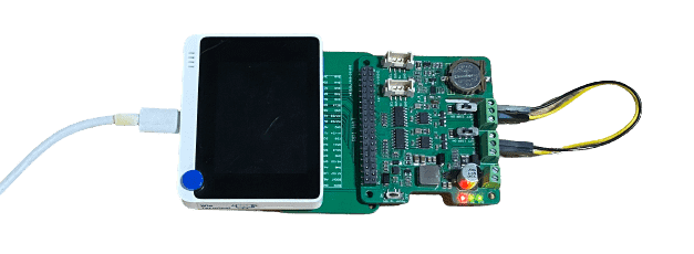
Exemplo de código de auto envio‑recepção
Este é um exemplo de envio e recepção de dados CAN-BUS por conta própria usando o Shield CAN-BUS(FD) de 2 canais para Raspberry Pi (MCP2518FD).
Conexão de hardware
-
Conecte o
Channel 0 Ldo Shield CAN-BUS(FD) de 2 canais para Raspberry Pi (MCP2518FD) aoChannel 1 Ldo Shield CAN-BUS(FD) de 2 canais para Raspberry Pi (MCP2518FD). -
Conecte o
Channel 0 Hdo Shield CAN-BUS(FD) de 2 canais para Raspberry Pi (MCP2518FD) aoChannel 1 Hdo Shield CAN-BUS(FD) de 2 canais para Raspberry Pi (MCP2518FD).
#include <SPI.h>
#include "mcp2518fd_can.h"

/*SAMD core*/
#ifdef ARDUINO_SAMD_VARIANT_COMPLIANCE
    #define SERIAL SerialUSB
#else
    #define SERIAL Serial
#endif

// Set SPI CS Pin according to your hardware
// For Wio Terminal w/ MCP2518FD RPi Hat:
// Channel 0 SPI_CS Pin: BCM 8
// Channel 1 SPI_CS Pin: BCM 7
// Interupt Pin: BCM25
// *****************************************
// For Arduino MCP2515 Hat:
// SPI_CS Pin: D9

const int SPI_CS_PIN_SEND = BCM8;
const int SPI_CS_PIN_RECEIVE = BCM7;

mcp2518fd CAN_SEND(SPI_CS_PIN_SEND);
mcp2518fd CAN_RECEIVE(SPI_CS_PIN_RECEIVE);

unsigned char len = 0;
unsigned char buf[8];

void setup() {
    SERIAL.begin(115200);
    while(!Serial); // wait for Serial

    if (CAN_SEND.begin((byte)CAN_500K_1M) != 0 || CAN_RECEIVE.begin((byte)CAN_500K_1M) != 0) {
      Serial.println("CAN-BUS initiliased error!");
      while(1);
    }

    SERIAL.println("CAN BUS Shield init ok!");
}

unsigned char stmp[8] = {0, 0, 0, 0, 0, 0, 0, 0};
void loop() {
    // send data:  id = 0x00, standrad frame, data len = 8, stmp: data buf
    stmp[7] = stmp[7] + 1;
    if (stmp[7] == 100) {
        stmp[7] = 0;
        stmp[6] = stmp[6] + 1;

        if (stmp[6] == 100) {
            stmp[6] = 0;
            stmp[5] = stmp[6] + 1;
        }
    }

    CAN_SEND.sendMsgBuf(0x00, 0, 8, stmp);
    delay(100);                       // send data per 100ms
    SERIAL.println("CAN BUS sendMsgBuf ok!");

    // ---------------------

    if (CAN_MSGAVAIL == CAN_RECEIVE.checkReceive()) {
    // read data,  len: data length, buf: data buf
      SERIAL.println("checkReceive");
      CAN_RECEIVE.readMsgBuf(&len, buf);
    // print the data
    for (int i = 0; i < len; i++) {
        SERIAL.print(buf[i]); SERIAL.print(" ");
    }
    SERIAL.println();
    }
    SERIAL.println("---LOOP END---");
}
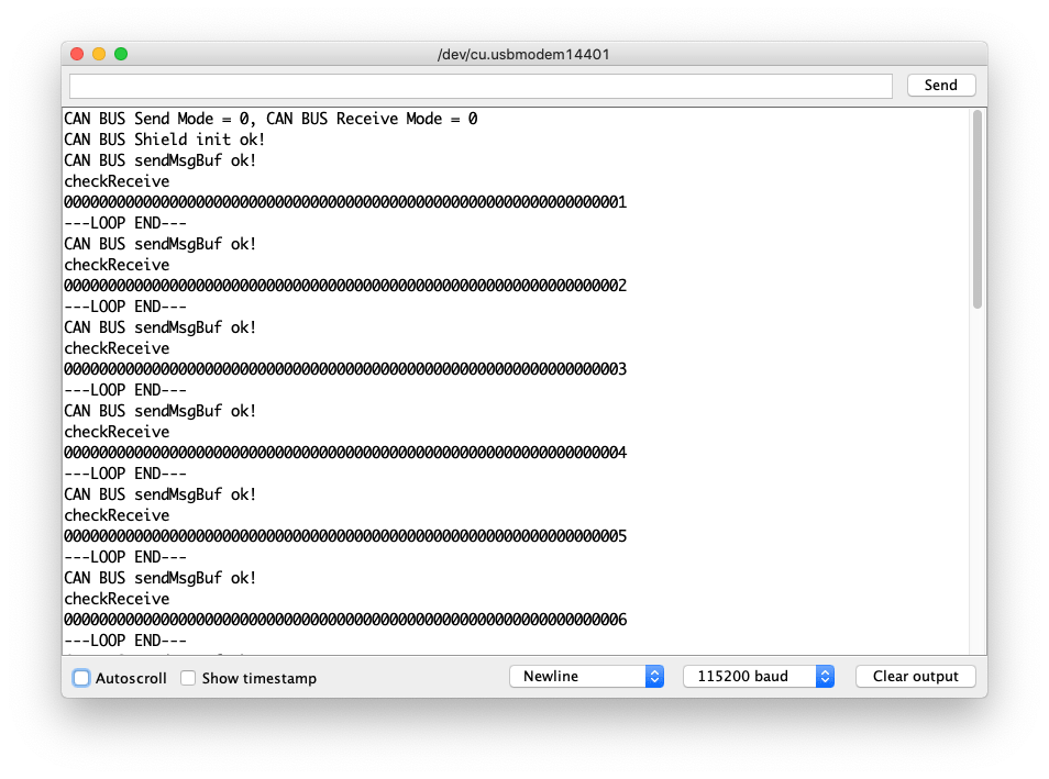
Exemplo de código de envio FD
Este é um exemplo de envio e recepção de dados CAN-BUS (até 64 bits) usando o protocolo FD por conta própria utilizando o Shield CAN-BUS(FD) de 2 canais para Raspberry Pi (MCP2518FD).
Conexão de hardware
Mesma conexão do exemplo de auto envio‑recepção.
#include <SPI.h>
#include "mcp2518fd_can.h"

/*SAMD core*/
#ifdef ARDUINO_SAMD_VARIANT_COMPLIANCE
    #define SERIAL SerialUSB
#else
    #define SERIAL Serial
#endif

// Set SPI CS Pin according to your hardware
// For Wio Terminal w/ MCP2518FD RPi Hat:
// Channel 0 SPI_CS Pin: BCM 8
// Channel 1 SPI_CS Pin: BCM 7
// Interupt Pin: BCM25
// *****************************************
// For Arduino MCP2515 Hat:
// SPI_CS Pin: D9

const int SPI_CS_PIN_SEND = BCM8;
const int SPI_CS_PIN_RECEIVE = BCM7;

mcp2518fd CAN_SEND(SPI_CS_PIN_SEND);
mcp2518fd CAN_RECEIVE(SPI_CS_PIN_RECEIVE);

void setup() {
    SERIAL.begin(115200);
    while(!Serial); // wait for Serial
    CAN_SEND.setMode(0);
    CAN_RECEIVE.setMode(0);

    if (CAN_SEND.begin((byte)CAN_500K_1M) != 0 || CAN_RECEIVE.begin((byte)CAN_500K_1M) != 0) {
      Serial.println("CAN-BUS initiliased error!");
      while(1);
    }
    byte send_mode = CAN_SEND.getMode();
    byte receive_mode = CAN_RECEIVE.getMode();
    SERIAL.printf("CAN BUS Send Mode = %d, CAN BUS Receive Mode = %d\n\r",send_mode, receive_mode);
    SERIAL.println("CAN BUS Shield init ok!");
}

unsigned char stmp[64] = {0};
unsigned char len = 0;
unsigned char buf[64];

void loop() {
    stmp[63] = stmp[63] + 1;
    if (stmp[63] == 100) {
        stmp[63] = 0;
        stmp[62] = stmp[62] + 1;

        if (stmp[62] == 100) {
            stmp[62] = 0;
            stmp[61] = stmp[62] + 1;
        }
    }

    CAN_SEND.sendMsgBuf(0x00, 0, 15, stmp);
    delay(100);                       // send data per 100ms
    SERIAL.println("CAN BUS sendMsgBuf ok!");

    // ---------------------

    if (CAN_MSGAVAIL == CAN_RECEIVE.checkReceive()) {
    // read data,  len: data length, buf: data buf
      SERIAL.println("checkReceive");
      CAN_RECEIVE.readMsgBuf(&len, buf);
    // print the data
    for (int i = 0; i < len; i++) {
        SERIAL.print(buf[i]); SERIAL.print(" ");
    }
    SERIAL.println();
    }
    SERIAL.println("---LOOP END---");
}
Visualizador de Esquemático Online
Recursos
- [PDF] Esquemáticos do Shield CAN-BUS(FD) de 2 Canais para Raspberry Pi (MCP2518FD)
- [ZIP] Arquivo de esquemático do Shield CAN-BUS(FD) de 2 Canais para Raspberry Pi
- [ZIP] Arquivo de esquemático do Hat Master CAN FD de 2 Canais para RPi
- [PDF] Datasheet MCP2517
- [PDF] Datasheet MCP2557
Suporte Técnico e Discussão de Produto
Obrigado por escolher nossos produtos! Estamos aqui para fornecer diferentes tipos de suporte para garantir que sua experiência com nossos produtos seja o mais tranquila possível. Oferecemos vários canais de comunicação para atender a diferentes preferências e necessidades.