Grove - 6-Axis Accelerometer&Compass V2.0

O Grove – 6-Axis Accelerometer&Compass V2.0 é um acelerômetro de 3 eixos combinado com um sensor magnético de 3 eixos. É uma versão atualizada do Grove - 6-Axis Accelerometer&Compass V1.0 e é baseado no módulo de sensor LSM303D, que possui uma faixa de escala completa de aceleração linear selecionável de ±2g / ±4g / ±8g / ±16g e uma faixa de escala completa de campo magnético selecionável de ±2 / ±4 / ±8 / ±12 gauss. As partes magnéticas e as partes do acelerômetro podem ser desligadas separadamente para reduzir o consumo de energia. O Arduino pode obter esses dados via interface I2C com a biblioteca fornecida para este módulo.

Especificações
- Tensão de entrada: 5V
- Interface I2C e interface SPI selecionável
- Faixa de medição selecionável
- Detecção de orientação em 6D
- 2 geradores de interrupção programáveis independentes
- Modo de desligamento
- Endereço I2C 0x1E (padrão) ou 0x1D
Se você quiser usar múltiplos dispositivos I2C, consulte Software I2C.
Para mais detalhes sobre módulos Grove, consulte Grove System
Plataformas compatíveis
| Arduino | Raspberry Pi |
|---|---|
|
|
As plataformas mencionadas acima como compatíveis são uma indicação da compatibilidade de software ou teórica do módulo. Na maioria dos casos, fornecemos apenas biblioteca de software ou exemplos de código para a plataforma Arduino. Não é possível fornecer biblioteca de software / código de demonstração para todas as possíveis plataformas de MCU. Portanto, os usuários precisam escrever sua própria biblioteca de software.
Visão geral do hardware

- ① Interface Grove, conecta à I2C
- ② Interface SPI
- ③ Trilha de seleção I2C ou SPI (padrão é I2C); se quiser usar SPI, desconecte esta trilha
- ④ Saída digital de interrupção
- ⑤ Trilha de seleção de endereço, por padrão conectada entre b e a, o endereço é 0x1E; se conectar b e c o endereço é 0x1D; se quiser usar SPI, desconecte esta trilha de qualquer lado.
Primeiros passos
O LSM303D é um módulo sensor 6D que contém um acelerômetro 3D e um sensor magnético 3D. Ele possui uma interface digital I2C, de forma que o conversor analógico-digital é dispensado.
O MCU pode coletar dados do sensor 6D diretamente pela interface I2C. Ok, vamos começar a usar este módulo sensor LSM303D 6D.
Brincar com Arduino
Hardware
- Passo 1. Prepare os itens abaixo:
| Seeeduino V4.2 | Base Shield | Grove-6-Axis_AccelerometerAndCompass_V2.0 |
|---|---|---|
|
|
|
| Adquira agora | Adquira agora | Adquira agora |


- Passo 2. Conecte o Grove-6-Axis_AccelerometerAndCompass_V2 à porta I2C do Grove-Base Shield.
- Passo 3. Conecte o Grove - Base Shield ao Seeeduino.
- Passo 4. Conecte o Seeeduino ao PC por meio de um cabo USB.

Se não tivermos o Grove Base Shield, também podemos conectar este módulo diretamente ao Seeeduino como abaixo.
| Seeeduino_v4 | Grove-6-Axis_AccelerometerAndCompass_V2 |
|---|---|
| 5V | VCC |
| GND | GND |
| SDA | SDA |
| SCL | SCL |
Software
Passo 1. Baixe a biblioteca do Github.
Passo 2. Consulte How to install library para instalar a biblioteca para Arduino.
Passo 3. Crie um novo sketch Arduino e cole o código abaixo nele ou abra o código diretamente pelo caminho: File -> Example ->Accelerometer_Compass->Accelerometer_Compass.
Passo 4. Envie o código. Se você não souber como enviar o código, verifique how to upload code.
Aqui está o código
/* LSM303DLM Example Code base on LSM303DLH example code by Jim Lindblom SparkFun Electronics

   date: 9/6/11
   license: Creative commons share-alike v3.0

   Modified by:Frankie.Chu
   Modified by:Jacky.Zhang 2014-12-11: Ported to 6-Axis Accelerometer&Compass of Seeed Studio
   Modified by:Jacky.Zhang 2015-1-6: added SPI driver

   Summary:
   Show how to calculate level and tilt-compensated heading using
   the snazzy LSM303DLH 3-axis magnetometer/3-axis accelerometer.

   Firmware:
   You can set the accelerometer's full-scale range by setting
   the SCALE constant to either 2, 4, or 8. This value is used
   in the initLSM303() function. For the most part, all other
   registers in the LSM303 will be at their default value.

   Use the write() and read() functions to write
   to and read from the LSM303's internal registers.

   Use getLSM303_accel() and getLSM303_mag() to get the acceleration
   and magneto values from the LSM303. You'll need to pass each of
   those functions an array, where the data will be stored upon
   return from the void.

   getHeading() calculates a heading assuming the sensor is level.
   A float between 0 and 360 is returned. You need to pass it a
   array with magneto values.

   getTiltHeading() calculates a tilt-compensated heading.
   A float between 0 and 360 degrees is returned. You need
   to pass this function both a magneto and acceleration array.

   Headings are calculated as specified in AN3192:
   http://www.sparkfun.com/datasheets/Sensors/Magneto/Tilt%20Compensated%20Compass.pdf
*/

/*
hardware & software comment
I2C mode:
1, solder the jumper "I2C EN" and the jumper of ADDR to 0x1E
2, use Lsm303d.initI2C() function to initialize the Grove by I2C
SPI mode:
1, break the jumper "I2C_EN" and the jumper ADDR to any side
2, define a pin as chip select for SPI protocol.
3, use Lsm303d.initSPI(SPI_CS) function to initialize the Grove by SPI
SPI.h sets these for us in arduino
const int SDI = 11;
const int SDO = 12;
const int SCL = 13;
*/

#include <LSM303D.h>
#include <Wire.h>
#include <SPI.h>

/* Global variables */
int accel[3];  // we'll store the raw acceleration values here
int mag[3];  // raw magnetometer values stored here
float realAccel[3];  // calculated acceleration values here
float heading, titleHeading;

#define SPI_CS 10

void setup()
{
 char rtn = 0;
    Serial.begin(9600);  // Serial is used for debugging
    Serial.println("\r\npower on");
    rtn = Lsm303d.initI2C();
    //rtn = Lsm303d.initSPI(SPI_CS);
    if(rtn != 0)  // Initialize the LSM303, using a SCALE full-scale range
 {
  Serial.println("\r\nLSM303D is not found");
  while(1);
 }
 else
 {
  Serial.println("\r\nLSM303D is found");
 }
}

void loop()
{
 Serial.println("\r\n**************");
 //getLSM303_accel(accel);  // get the acceleration values and store them in the accel array
 Lsm303d.getAccel(accel);
 while(!Lsm303d.isMagReady());// wait for the magnetometer readings to be ready
 Lsm303d.getMag(mag);  // get the magnetometer values, store them in mag

 for (int i=0; i<3; i++)
 {
  realAccel[i] = accel[i] / pow(2, 15) * ACCELE_SCALE;  // calculate real acceleration values, in units of g
 }
 heading = Lsm303d.getHeading(mag);
 titleHeading = Lsm303d.getTiltHeading(mag, realAccel);

 printValues();

 delay(200);  // delay for serial readability
}

void printValues()
{
 Serial.println("Acceleration of X,Y,Z is");
 for (int i=0; i<3; i++)
 {
  Serial.print(realAccel[i]);
  Serial.println("g");
 }
 //print both the level, and tilt-compensated headings below to compare
 Serial.println("The clockwise angle between the magnetic north and x-axis: ");
 Serial.print(heading, 3); // this only works if the sensor is level
 Serial.println(" degrees");
 Serial.print("The clockwise angle between the magnetic north and the projection");
 Serial.println(" of the positive x-axis in the horizontal plane: ");
 Serial.print(titleHeading, 3);  // see how awesome tilt compensation is?!
 Serial.println(" degrees");
}
Passo 5. Abra o monitor serial, você verá o resultado de saída do Sensor de Cor como mostrado abaixo:

Passo 6. Você pode ver os valores de aceleração e o ângulo horário entre o norte magnético e o eixo x.
O X/Y/Z mostra a aceleração nos 3 eixos; e então é calculado o ângulo entre o norte magnético e o eixo x.
E também é calculado o ângulo entre o norte magnético e a projeção do eixo x positivo.
Brincar com Raspberry Pi
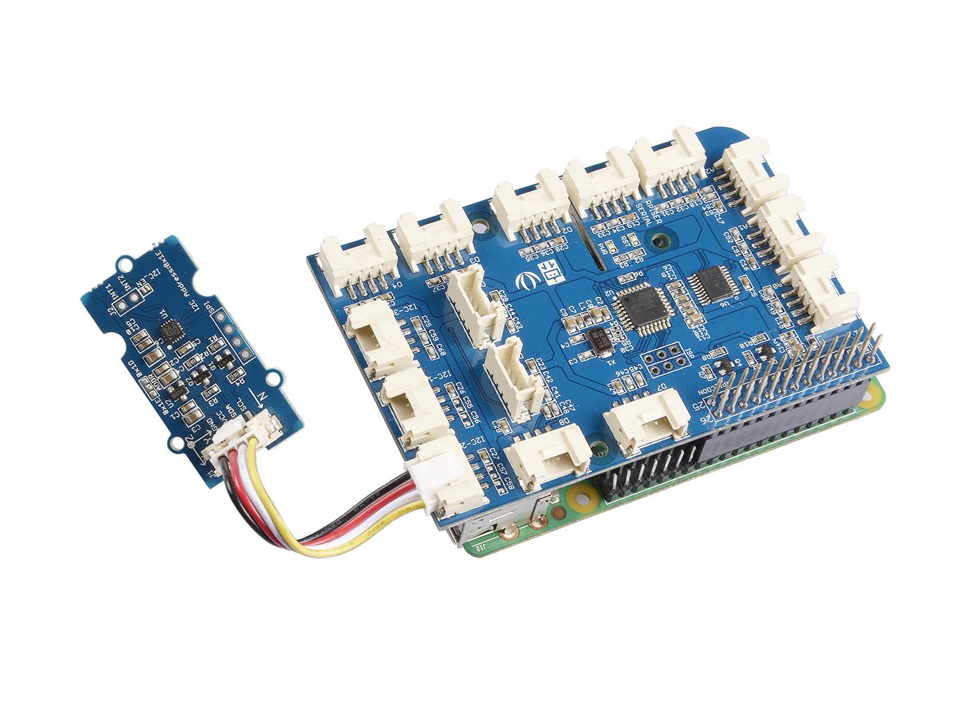
Hardware
- Passo 1. Prepare os itens abaixo:
| Raspberry pi | GrovePi_Plus | Grove-6-Axis_AccelerometerAndCompass_V2.0 |
|---|---|---|
|
|
|
| Adquira um Agora | Adquira um Agora | Adquira um Agora |

- Passo 2. Conecte o GrovePi_Plus ao Raspberry.
- Passo 3. Conecte o Grove-6-Axis_AccelerometerAndCompass_V2.0 à porta I2C do GrovePi_Plus.
- Passo 4. Conecte o Raspberry ao PC por meio de um cabo USB.
Software
- Passo 1. Siga Setting Software para configurar o ambiente de desenvolvimento.
- Passo 2. Dê um git clone no repositório do Github.
cd ~
git clone https://github.com/DexterInd/GrovePi.git
- Passo 3. Execute os comandos abaixo para usar este sensor
cd ~/GrovePi/Software/Python/grove_6axis_acc_compass
python grove_6axis_accel_compass_example.py
Aqui está o código de exemplo:
#!/usr/bin/env python
#
# GrovePi example for using the Grove - 6-Axis Accelerometer&Compass v2.0(https://www.seeedstudio.com/depot/Grove-6Axis-AccelerometerCompass-v20-p-2476.html)
#
# The GrovePi connects the Raspberry Pi and Grove sensors.  You can learn more about GrovePi here:  http://www.dexterindustries.com/GrovePi
#
# Have a question about this library?  Ask on the forums here:  http://forum.dexterindustries.com/c/grovepi
#
'''
## License
The MIT License (MIT)
GrovePi for the Raspberry Pi: an open source platform for connecting Grove Sensors to the Raspberry Pi.
Copyright (C) 2017  Dexter Industries
Permission is hereby granted, free of charge, to any person obtaining a copy
of this software and associated documentation files (the "Software"), to deal
in the Software without restriction, including without limitation the rights
to use, copy, modify, merge, publish, distribute, sublicense, and/or sell
copies of the Software, and to permit persons to whom the Software is
furnished to do so, subject to the following conditions:
The above copyright notice and this permission notice shall be included in
all copies or substantial portions of the Software.
THE SOFTWARE IS PROVIDED "AS IS", WITHOUT WARRANTY OF ANY KIND, EXPRESS OR
IMPLIED, INCLUDING BUT NOT LIMITED TO THE WARRANTIES OF MERCHANTABILITY,
FITNESS FOR A PARTICULAR PURPOSE AND NONINFRINGEMENT. IN NO EVENT SHALL THE
AUTHORS OR COPYRIGHT HOLDERS BE LIABLE FOR ANY CLAIM, DAMAGES OR OTHER
LIABILITY, WHETHER IN AN ACTION OF CONTRACT, TORT OR OTHERWISE, ARISING FROM,
OUT OF OR IN CONNECTION WITH THE SOFTWARE OR THE USE OR OTHER DEALINGS IN
THE SOFTWARE.
'''
import lsm303d

try:
 acc_mag=lsm303d.lsm303d()

 while True:

  # Get accelerometer values
  acc=acc_mag.getRealAccel()

  # Wait for compass to get ready
  while True:
   if acc_mag.isMagReady():
    break

  # Read the heading
  heading= acc_mag.getHeading()

  print("Acceleration of X,Y,Z is %.3fg, %.3fg, %.3fg" %(acc[0],acc[1],acc[2]))
  print("Heading %.3f degrees\n" %(heading))

except IOError:
 print("Unable to read from accelerometer, check the sensor and try again")
Aqui está o resultado:

Referências
Clique aqui para saber mais sobre este parâmetro.


Notas
1. Todos os acelerômetros ST MEMS são calibrados de fábrica, permitindo ao usuário evitar qualquer calibração adicional para a maioria das aplicações. No entanto, para alcançar uma precisão de rumo abaixo de 2°, é necessário um procedimento simples de calibração.
2. Ao testar o ângulo horário entre o norte magnético e o eixo x, você pode alinhar o eixo Xa do dispositivo com qualquer direção, mas não o deixe virado para baixo. Consulte a imagem abaixo:

Recursos
-
[Library] Biblioteca 6-Axis Accelerometer&Compass v2.0 para arduino
-
[Library] Biblioteca 6-Axis Accelerometer&Compass v2.0 para raspberry pi
-
[Datasheet] LSM303D_datashet
Suporte Técnico & Discussão de Produto
Obrigado por escolher nossos produtos! Estamos aqui para oferecer diferentes formas de suporte para garantir que sua experiência com nossos produtos seja a mais tranquila possível. Oferecemos diversos canais de comunicação para atender a diferentes preferências e necessidades.