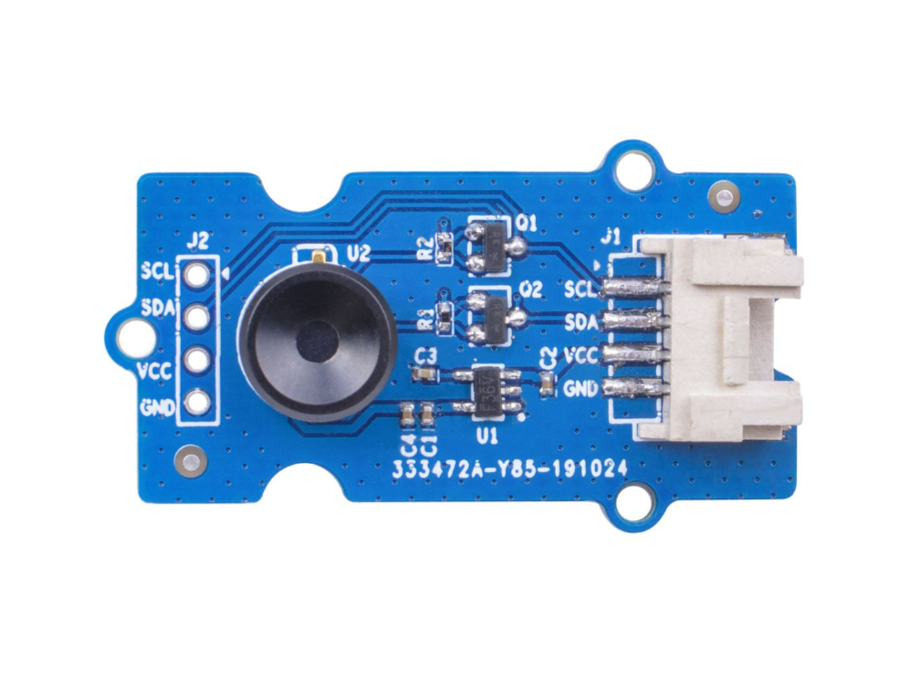
Grove - Câmera de Imagem Térmica Matriz IR MLX90641
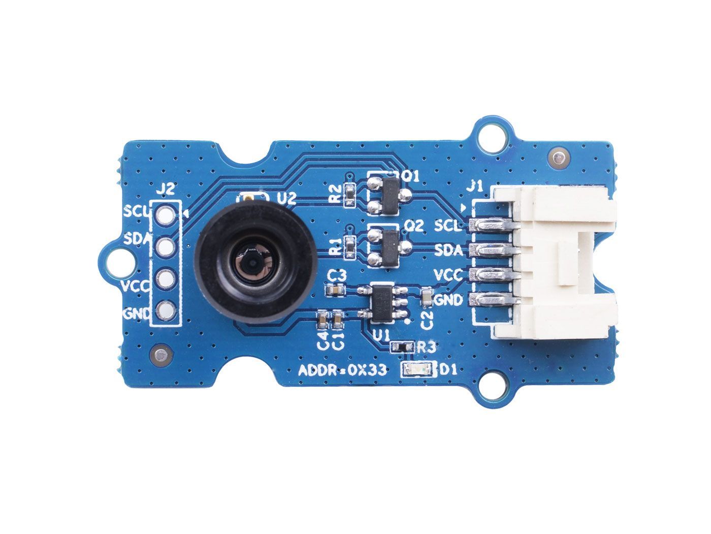
Esta câmera térmica IR possui uma matriz de 16x12 sensores térmicos (MLX90641) e pode detectar a temperatura de objetos a uma certa distância, com precisão de ±1℃ na área central e precisão média de ±1,5℃. Para obter facilmente as imagens térmicas, é utilizado o protocolo I2C para receber as imagens de baixa resolução da câmera. O FOV (Campo de Visão) desta câmera é de 110°x75°, e a faixa de medição de temperatura é de -40℃ a 300℃. Para obter a imagem térmica com facilidade, é utilizado o protocolo I2C para receber a imagem de baixa resolução da câmera.
Já a Grove - Câmera de Imagem Térmica é um sensor térmico (MLX90640), com uma matriz de 32x24 sensores térmicos, que pode detectar a temperatura de objetos a alguns pés de distância com precisão de ±1,5℃, além de apresentar imagens térmicas dinâmicas e detectar a temperatura ambiente de -40℃~300℃. A câmera com ângulo estreito/amplo possui um FOV (Campo de Visão) de 55°x35°/110°x75°. Para obter a imagem térmica com facilidade, é utilizado o protocolo I2C para receber a imagem de baixa resolução da câmera.
Versões
| Versão | Data de Lançamento | Pedido |
|---|---|---|
| Grove - Câmera de Imagem Térmica / Matriz IR MLX90641 110 graus [New] | 03-jun-2020 | Buy it |
| Grove - Câmera de Imagem Térmica / Matriz IR MLX90640 110 graus | 12-nov-2019 | Buy it |
Este wiki serve para ambos os tipos de Câmera de Imagem Térmica Matriz IR MLX90641 e MLX90640.
Recursos
- Tamanho compacto, matriz de sensor térmico IR de 16x12 pixels (MLX90641), matriz de sensor térmico IR de 32x24 pixels (MLX90640)
- Alto FOV (campo de visão) de 110°x75° para capturar uma área maior
- Ampla faixa de medição de temperatura (-40℃~300℃)
- Interface Grove I2C para comunicação fácil com um MCU
- Matriz IR totalmente calibrada para configuração conveniente
Especificação
| Item | Grove - Câmera de Imagem Térmica - MLX90640 | Grove - Câmera de Imagem Térmica - MLX90641 |
|---|---|---|
| Sensor térmico | Matriz de 32x24 MLX90640 | Matriz de 16x12 MLX90641 |
| Tensão de Operação | 3,3V - 5V | 3,3V - 5V |
| Consumo de corrente | ~18mA | ~18mA |
| FOV (Campo de Visão) | 110°x75° | 110°x75° |
| Faixa de Medição de Temperatura | -40°C - 300°C | -40°C - 300°C |
| Resolução de Temperatura | ± 1,5°C | ± 1,5°C (±1℃ na área central) |
| Taxa de Atualização | 0,5Hz - 64Hz | 0,5Hz - 64Hz |
| Interface | Interface Grove I2C | Interface Grove I2C |
| Endereço I2C | 0x33 | 0x33 |
Plataformas Suportadas
| Arduino | Raspberry Pi | |||
|---|---|---|---|---|
Primeiros Passos
Primeiros Passos com o Wio Terminal
Materiais necessários
| Wio Terminal | Grove - Câmera de Imagem Térmica / Matriz IR MLX90641 110 graus |
|---|---|
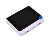 |  |
| Adquira agora | Adquira agora |
Conexão de Hardware
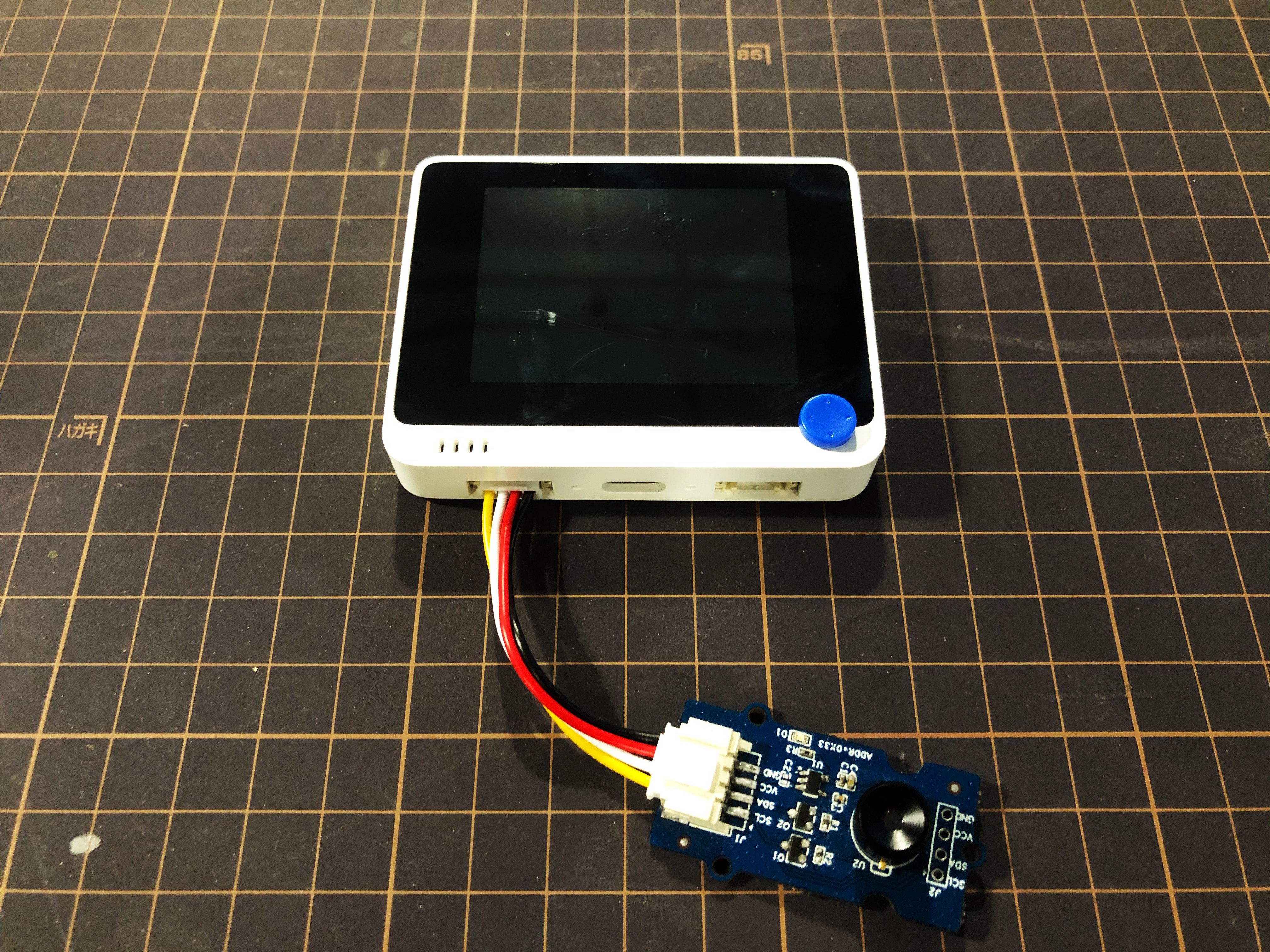
Passo 1. Conecte a Grove - Câmera de Imagem Térmica ao Wio Terminal por meio de um cabo Grove e também conecte o Wio Terminal ao PC através de um cabo USB.
Passo 2. Baixe a Library e copie todo o arquivo Seeed_Arduino_MLX9064x e cole-o na pasta de bibliotecas do seu Arduino IDE.
Se esta é a sua primeira vez usando o Wio Terminal e você não tem certeza em qual interface conectar no Wio Terminal, consulte Get Started with Wio Terminal.
Passo 3. Copie o Código de Software 1 abaixo para o seu Arduino IDE e faça o upload para que o formato de visualização seja exibido via Serial Port.
Resultado do Formato de Visualização
Código de Software 1
/*
    Output the temperature readings to all pixels to be read by a Processing visualizer
*/

#include <Wire.h>

#define USE_MLX90641

#ifndef USE_MLX90641
    #include "MLX90640_API.h"
#else
    #include "MLX90641_API.h"
#endif

#include "MLX9064X_I2C_Driver.h"

#if defined(ARDUINO_ARCH_AVR)
    #define debug  Serial

#elif defined(ARDUINO_ARCH_SAMD) ||  defined(ARDUINO_ARCH_SAM)
    #define debug  Serial
#else
    #define debug  Serial
#endif

#ifdef USE_MLX90641
    const byte MLX90641_address = 0x33; //Default 7-bit unshifted address of the MLX90641
    #define TA_SHIFT 8 //Default shift for MLX90641 in open air

    uint16_t eeMLX90641[832];
    float MLX90641To[192];
    uint16_t MLX90641Frame[242];
    paramsMLX90641 MLX90641;
    int errorno = 0;
#else
    const byte MLX90640_address = 0x33; //Default 7-bit unshifted address of the MLX90640

    #define TA_SHIFT 8 //Default shift for MLX90640 in open air

    float mlx90640To[768];
    paramsMLX90640 mlx90640;
#endif
void setup() {
    Wire.begin();
    Wire.setClock(400000); //Increase I2C clock speed to 400kHz

    debug.begin(115200); //Fast debug as possible

    while (!debug); //Wait for user to open terminal
    //debug.println("MLX90640 IR Array Example");


#ifndef USE_MLX90641
    if (isConnected() == false) {
        debug.println("MLX9064x not detected at default I2C address. Please check wiring. Freezing.");
        while (1);
    }
    //Get device parameters - We only have to do this once
    int status;
    uint16_t eeMLX90640[832];
    status = MLX90640_DumpEE(MLX90640_address, eeMLX90640);
    if (status != 0) {
        debug.println("Failed to load system parameters");
    }

    status = MLX90640_ExtractParameters(eeMLX90640, &mlx90640);
    if (status != 0) {
        debug.println("Parameter extraction failed");
    }

    //Once params are extracted, we can release eeMLX90640 array

    //MLX90640_SetRefreshRate(MLX90640_address, 0x02); //Set rate to 2Hz
    MLX90640_SetRefreshRate(MLX90640_address, 0x03); //Set rate to 4Hz
    //MLX90640_SetRefreshRate(MLX90640_address, 0x07); //Set rate to 64H
#else
    if (isConnected() == false) {
        debug.println("MLX90641 not detected at default I2C address. Please check wiring. Freezing.");
        while (1);
    }
    //Get device parameters - We only have to do this once
    int status;
    status = MLX90641_DumpEE(MLX90641_address, eeMLX90641);
    errorno = status;//MLX90641_CheckEEPROMValid(eeMLX90641);//eeMLX90641[10] & 0x0040;//

    if (status != 0) {
        debug.println("Failed to load system parameters");
       while(1);
    }

    status = MLX90641_ExtractParameters(eeMLX90641, &MLX90641);
    //errorno = status;
    if (status != 0) {
        debug.println("Parameter extraction failed");
        while(1);
    }

    //Once params are extracted, we can release eeMLX90641 array

    //MLX90641_SetRefreshRate(MLX90641_address, 0x02); //Set rate to 2Hz
    MLX90641_SetRefreshRate(MLX90641_address, 0x03); //Set rate to 4Hz
    //MLX90641_SetRefreshRate(MLX90641_address, 0x07); //Set rate to 64Hz
#endif

}

void loop() {
#ifndef USE_MLX90641
    long startTime = millis();
    for (byte x = 0 ; x < 2 ; x++) {
        uint16_t mlx90640Frame[834];
        int status = MLX90640_GetFrameData(MLX90640_address, mlx90640Frame);

        float vdd = MLX90640_GetVdd(mlx90640Frame, &mlx90640);
        float Ta = MLX90640_GetTa(mlx90640Frame, &mlx90640);

        float tr = Ta - TA_SHIFT; //Reflected temperature based on the sensor ambient temperature
        float emissivity = 0.95;

        MLX90640_CalculateTo(mlx90640Frame, &mlx90640, emissivity, tr, mlx90640To);
    }
    long stopTime = millis();

    for (int x = 0 ; x < 768 ; x++) {
        //if(x % 8 == 0) debug.println();
        debug.print(mlx90640To[x], 2);
        debug.print(",");
    }
    debug.println("");
#else
    long startTime = millis();

    for (byte x = 0 ; x < 2 ; x++) {
        int status = MLX90641_GetFrameData(MLX90641_address, MLX90641Frame);

        float vdd = MLX90641_GetVdd(MLX90641Frame, &MLX90641);
        float Ta = MLX90641_GetTa(MLX90641Frame, &MLX90641);

        float tr = Ta - TA_SHIFT; //Reflected temperature based on the sensor ambient temperature
        float emissivity = 0.95;

        MLX90641_CalculateTo(MLX90641Frame, &MLX90641, emissivity, tr, MLX90641To);
    }
    long stopTime = millis();
   /*
    debug.print("vdd=");
    debug.print(vdd,2);
    debug.print(",Ta=");
    debug.print(Ta,2);

    debug.print(",errorno=");
    debug.print(errorno,DEC);


    for (int x = 0 ; x < 64 ; x++) {
        debug.print(MLX90641Frame[x], HEX);
        debug.print(",");
    }

    delay(1000);
    */
    for (int x = 0 ; x < 192 ; x++) {
        debug.print(MLX90641To[x], 2);
        debug.print(",");
    }
    debug.println("");
#endif
}

//Returns true if the MLX90640 is detected on the I2C bus
boolean isConnected() {
#ifndef USE_MLX90641
    Wire.beginTransmission((uint8_t)MLX90640_address);
#else
    Wire.beginTransmission((uint8_t)MLX90641_address);
#endif
    if (Wire.endTransmission() != 0) {
        return (false);    //Sensor did not ACK
    }
    return (true);
}
Carregue o código de software 1 acima no seu Arduino IDE e abra a Serial Port; você verá um resultado em formato de visualização como a seguir:
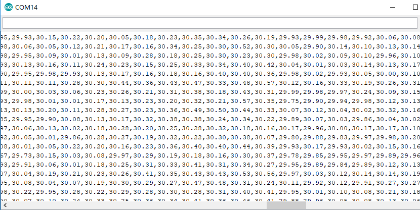
Resultado da visualização no Wio Terminal
Passo 4. Carregue o Código de Software 2 abaixo no seu Arduino IDE para a visualização exibida no Wio Terminal.
Código de Software 2
#include <Wire.h>
#include "MLX90641_API.h"
#include "MLX9064X_I2C_Driver.h"
#include <TFT_eSPI.h>                // Include the graphics library (this includes the sprite functions)

const byte MLX90641_address = 0x33; //Default 7-bit unshifted address of the MLX90641
#define TA_SHIFT 12 //Default shift for MLX90641 in open air
#define debug  Serial
uint16_t eeMLX90641[832];
float MLX90641To[192];
uint16_t MLX90641Frame[242];
paramsMLX90641 MLX90641;
int errorno = 0;

TFT_eSPI    tft = TFT_eSPI();
TFT_eSprite Display = TFT_eSprite(&tft);  // Create Sprite object "img" with pointer to "tft" object
// the pointer is used by pushSprite() to push it onto the TFT

unsigned long CurTime;

uint16_t TheColor;
// start with some initial colors
uint16_t MinTemp = 25;
uint16_t MaxTemp = 38;

// variables for interpolated colors
byte red, green, blue;

// variables for row/column interpolation
byte i, j, k, row, col, incr;
float intPoint, val, a, b, c, d, ii;
byte aLow, aHigh;

// size of a display "pixel"
byte BoxWidth = 3;
byte BoxHeight = 3;

int x, y;
char buf[20];

// variable to toggle the display grid
int ShowGrid = -1;

// array for the interpolated array
float HDTemp[6400];

void setup() {
    Wire.begin();
    Wire.setClock(2000000); //Increase I2C clock speed to 2M
    debug.begin(115200); //Fast debug as possible

    // start the display and set the background to black

    if (isConnected() == false) {
        debug.println("MLX90641 not detected at default I2C address. Please check wiring. Freezing.");
        while (1);
    }
    //Get device parameters - We only have to do this once
    int status;
    status = MLX90641_DumpEE(MLX90641_address, eeMLX90641);
    errorno = status;//MLX90641_CheckEEPROMValid(eeMLX90641);//eeMLX90641[10] & 0x0040;//

    if (status != 0) {
        debug.println("Failed to load system parameters");
       while(1);
    }

    status = MLX90641_ExtractParameters(eeMLX90641, &MLX90641);
    //errorno = status;
    if (status != 0) {
        debug.println("Parameter extraction failed");
        while(1);
    }

    //Once params are extracted, we can release eeMLX90641 array

    MLX90641_SetRefreshRate(MLX90641_address, 0x05); //Set rate to 16Hz

    tft.begin();
    tft.setRotation(3);
    tft.fillScreen(TFT_BLACK);
    Display.createSprite(TFT_HEIGHT, TFT_WIDTH);
    Display.fillSprite(TFT_BLACK);

    // get the cutoff points for the color interpolation routines
    // note this function called when the temp scale is changed
    Getabcd();

    // draw a legend with the scale that matches the sensors max and min
    DrawLegend();
}
void loop() {
    // draw a large white border for the temperature area
    Display.fillRect(10, 10, 220, 220, TFT_WHITE);
    for (byte x = 0 ; x < 2 ; x++) {
        int status = MLX90641_GetFrameData(MLX90641_address, MLX90641Frame);

        float vdd = MLX90641_GetVdd(MLX90641Frame, &MLX90641);
        float Ta = MLX90641_GetTa(MLX90641Frame, &MLX90641);

        float tr = Ta - TA_SHIFT; //Reflected temperature based on the sensor ambient temperature
        float emissivity = 0.95;

        MLX90641_CalculateTo(MLX90641Frame, &MLX90641, emissivity, tr, MLX90641To);
    }

    interpolate_image(MLX90641To,12,16,HDTemp,80,80);

    //display the 80 x 80 array
    DisplayGradient();

    //Crosshair in the middle of the screen
    Display.drawCircle(115, 115, 5, TFT_WHITE);
    Display.drawFastVLine(115, 105, 20, TFT_WHITE);
    Display.drawFastHLine(105, 115, 20, TFT_WHITE);
    //Displaying the temp at the middle of the Screen

    //Push the Sprite to the screen
    Display.pushSprite(0, 0);

    tft.setRotation(3);
    tft.setTextColor(TFT_WHITE);
    tft.drawFloat(HDTemp[35 * 80 + 35], 2, 90, 20);

}
//Returns true if the MLX90640 is detected on the I2C bus
boolean isConnected() {
    Wire.beginTransmission((uint8_t)MLX90641_address);
    if (Wire.endTransmission() != 0) {
        return (false);    //Sensor did not ACK
    }
    return (true);
}
// function to display the results
void DisplayGradient() {

  tft.setRotation(4);

  // rip through 70 rows
  for (row = 0; row < 70; row ++) {

    // fast way to draw a non-flicker grid--just make every 10 MLX90641To 2x2 as opposed to 3x3
    // drawing lines after the grid will just flicker too much
    if (ShowGrid < 0) {
      BoxWidth = 3;
    }
    else {
      if ((row % 10 == 9) ) {
        BoxWidth = 2;
      }
      else {
        BoxWidth = 3;
      }
    }
    // then rip through each 70 cols
    for (col = 0; col < 70; col++) {

      // fast way to draw a non-flicker grid--just make every 10 MLX90641To 2x2 as opposed to 3x3
      if (ShowGrid < 0) {
        BoxHeight = 3;
      }
      else {
        if ( (col % 10 == 9)) {
          BoxHeight = 2;
        }
        else {
          BoxHeight = 3;
        }
      }
      // finally we can draw each the 70 x 70 points, note the call to get interpolated color
      Display.fillRect((row * 3) + 15, (col * 3) + 15, BoxWidth, BoxHeight, GetColor(HDTemp[row * 80 + col]));
    }
  }

}
// my fast yet effective color interpolation routine
uint16_t GetColor(float val) {

  /*
    pass in value and figure out R G B
    several published ways to do this I basically graphed R G B and developed simple linear equations
    again a 5-6-5 color display will not need accurate temp to R G B color calculation

    equations based on
    http://web-tech.ga-usa.com/2012/05/creating-a-custom-hot-to-cold-temperature-color-gradient-for-use-with-rrdtool/index.html

  */

  red = constrain(255.0 / (c - b) * val - ((b * 255.0) / (c - b)), 0, 255);

  if ((val > MinTemp) & (val < a)) {
    green = constrain(255.0 / (a - MinTemp) * val - (255.0 * MinTemp) / (a - MinTemp), 0, 255);
  }
  else if ((val >= a) & (val <= c)) {
    green = 255;
  }
  else if (val > c) {
    green = constrain(255.0 / (c - d) * val - (d * 255.0) / (c - d), 0, 255);
  }
  else if ((val > d) | (val < a)) {
    green = 0;
  }

  if (val <= b) {
    blue = constrain(255.0 / (a - b) * val - (255.0 * b) / (a - b), 0, 255);
  }
  else if ((val > b) & (val <= d)) {
    blue = 0;
  }
  else if (val > d) {
    blue = constrain(240.0 / (MaxTemp - d) * val - (d * 240.0) / (MaxTemp - d), 0, 240);
  }

  // use the displays color mapping function to get 5-6-5 color palet (R=5 bits, G=6 bits, B-5 bits)
  return Display.color565(red, green, blue);

}

// function to get the cutoff points in the temp vs RGB graph
void Getabcd() {

  a = MinTemp + (MaxTemp - MinTemp) * 0.2121;
  b = MinTemp + (MaxTemp - MinTemp) * 0.3182;
  c = MinTemp + (MaxTemp - MinTemp) * 0.4242;
  d = MinTemp + (MaxTemp - MinTemp) * 0.8182;

}
float get_point(float *p, uint8_t rows, uint8_t cols, int8_t x, int8_t y)
{
    if (x < 0)
    {
        x = 0;
    }
    if (y < 0)
    {
        y = 0;
    }
    if (x >= cols)
    {
        x = cols - 1;
    }
    if (y >= rows)
    {
        y = rows - 1;
    }
    return p[y * cols + x];
}

void set_point(float *p, uint8_t rows, uint8_t cols, int8_t x, int8_t y, float f)
{
    if ((x < 0) || (x >= cols))
    {
        return;
    }
    if ((y < 0) || (y >= rows))
    {
        return;
    }
    p[y * cols + x] = f;
}

// src is a grid src_rows * src_cols
// dest is a pre-allocated grid, dest_rows*dest_cols
void interpolate_image(float *src, uint8_t src_rows, uint8_t src_cols,
                       float *dest, uint8_t dest_rows, uint8_t dest_cols)
{
    float mu_x = (src_cols - 1.0) / (dest_cols - 1.0);
    float mu_y = (src_rows - 1.0) / (dest_rows - 1.0);

    float adj_2d[16]; // matrix for storing adjacents

    for (uint8_t y_idx = 0; y_idx < dest_rows; y_idx++)
    {
        for (uint8_t x_idx = 0; x_idx < dest_cols; x_idx++)
        {
            float x = x_idx * mu_x;
            float y = y_idx * mu_y;
            get_adjacents_2d(src, adj_2d, src_rows, src_cols, x, y);

            float frac_x = x - (int)x; // we only need the ~delta~ between the points
            float frac_y = y - (int)y; // we only need the ~delta~ between the points
            float out = bicubicInterpolate(adj_2d, frac_x, frac_y);
            set_point(dest, dest_rows, dest_cols, x_idx, y_idx, out);
        }
    }
}

// p is a list of 4 points, 2 to the left, 2 to the right
float cubicInterpolate(float p[], float x)
{
    float r = p[1] + (0.5 * x * (p[2] - p[0] + x * (2.0 * p[0] - 5.0 * p[1] + 4.0 * p[2] - p[3] + x * (3.0 * (p[1] - p[2]) + p[3] - p[0]))));
    return r;
}

// p is a 16-point 4x4 array of the 2 rows & columns left/right/above/below
float bicubicInterpolate(float p[], float x, float y)
{
    float arr[4] = {0, 0, 0, 0};
    arr[0] = cubicInterpolate(p + 0, x);
    arr[1] = cubicInterpolate(p + 4, x);
    arr[2] = cubicInterpolate(p + 8, x);
    arr[3] = cubicInterpolate(p + 12, x);
    return cubicInterpolate(arr, y);
}

// src is rows*cols and dest is a 4-point array passed in already allocated!
void get_adjacents_1d(float *src, float *dest, uint8_t rows, uint8_t cols, int8_t x, int8_t y)
{
    // pick two items to the left
    dest[0] = get_point(src, rows, cols, x - 1, y);
    dest[1] = get_point(src, rows, cols, x, y);
    // pick two items to the right
    dest[2] = get_point(src, rows, cols, x + 1, y);
    dest[3] = get_point(src, rows, cols, x + 2, y);
}

// src is rows*cols and dest is a 16-point array passed in already allocated!
void get_adjacents_2d(float *src, float *dest, uint8_t rows, uint8_t cols, int8_t x, int8_t y)
{
    float arr[4];
    for (int8_t delta_y = -1; delta_y < 3; delta_y++)
    {                                          // -1, 0, 1, 2
        float *row = dest + 4 * (delta_y + 1); // index into each chunk of 4
        for (int8_t delta_x = -1; delta_x < 3; delta_x++)
        { // -1, 0, 1, 2
            row[delta_x + 1] = get_point(src, rows, cols, x + delta_x, y + delta_y);
        }
    }
}

// function to draw a legend
void DrawLegend() {

  //color legend with max and min text
  j = 0;

  float inc = (MaxTemp - MinTemp ) / 160.0;

  for (ii = MinTemp; ii < MaxTemp; ii += inc) {
    tft.drawFastHLine(260, 200 - j++, 30, GetColor(ii));
  }

  tft.setTextSize(2);
  tft.setCursor(245, 20);
  tft.setTextColor(TFT_WHITE, TFT_BLACK);
  sprintf(buf, "%2d/%2d", MaxTemp, (int) (MaxTemp * 1.12) + 32);
  tft.print(buf);

  tft.setTextSize(2);
  tft.setCursor(245, 210);
  tft.setTextColor(TFT_WHITE, TFT_BLACK);
  sprintf(buf, "%2d/%2d", MinTemp, (int) (MinTemp * 1.12) + 32);
  tft.print(buf);

}
O resultado da visualização será exibido na tela do Wio Terminal se tudo correr bem
Primeiros Passos com Raspberry Pi
Hardware
Materiais necessários
| Raspberry Pi 4 | Grove Base Hat para Raspberry Pi | Grove - Thermal Imaging Camera / IR Array MLX90641 110 degree |
|---|---|---|
 |  | |
| Adquira agora | Adquira agora | Adquira agora |
Conexão de Hardware
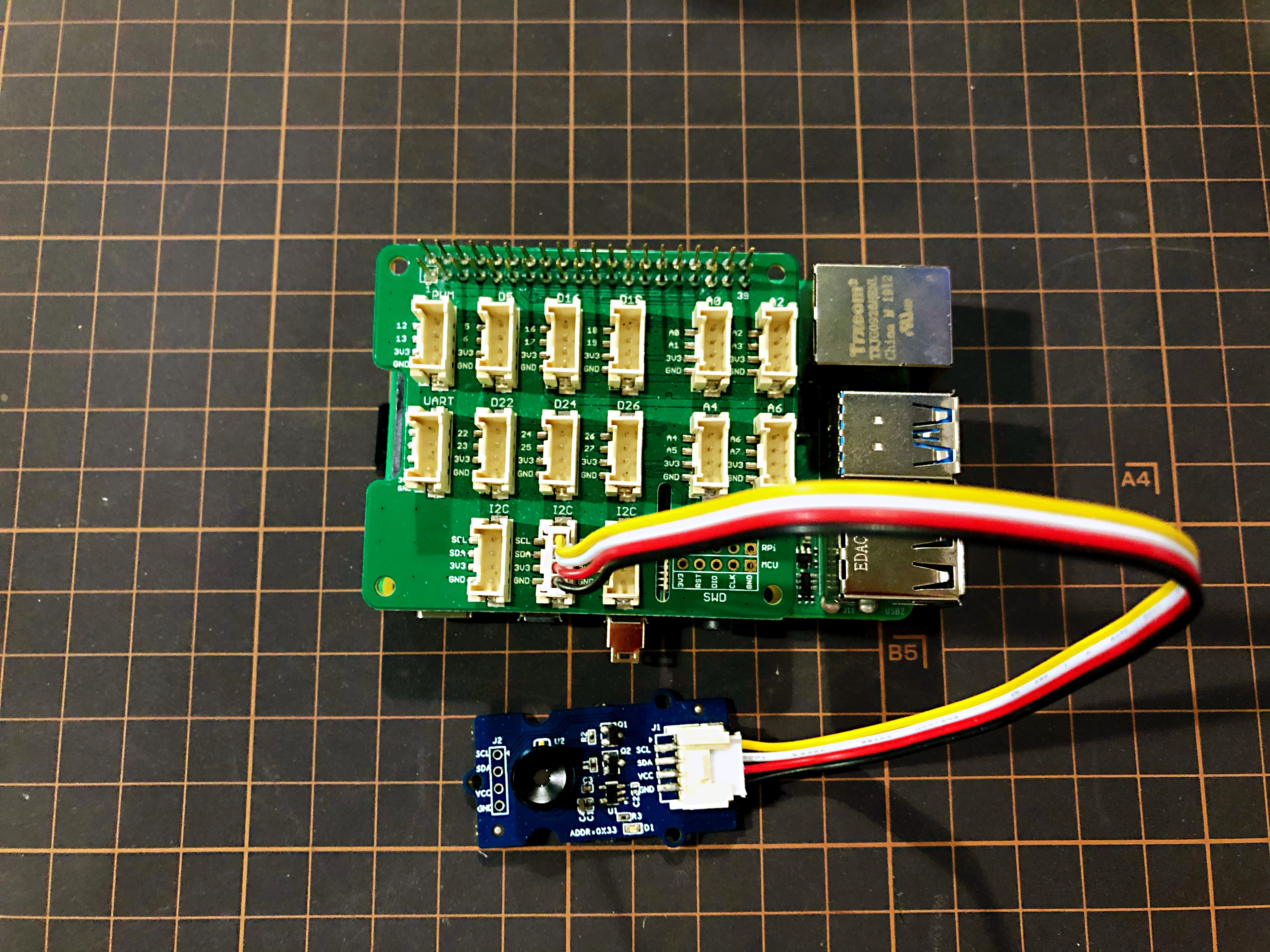
- Passo 1 Conecte a Grove - Thermal Imaging Camera a uma das duas portas I2C.
- Passo 2 Conecte a Raspberry Pi 4 ao Grove Base Hat para Raspberry Pi.
- Passo 3 Conecte a Raspberry Pi a um monitor via cabo HDMI e ligue a Raspberry Pi 4 pela porta USB tipo C.
Software
A Raspberry Pi 4 é compatível com Python, então o demo do projeto pode ser facilmente exibido pela tela da Raspberry Pi 4 se você seguir os passos abaixo.
- Passo 1 Instale o grove.py com o comando
pip3 install Seeed-grove.py
- Passo 2 Instale o driver MLX90641 com o seguinte comando. Ambiente Python (Se você não tiver autoridade na sua Raspberry Pi):
pip3 install seeed-python-mlx9064x
Atualize para o driver mais recente:
pip3 install --upgrade seeed-python-mlx9064x
- Passo 3 Verifique o número i2c correspondente da Raspberry Pi:
ls /dev/i2c*
Você pode obter um resultado como este:
/dev/i2c-1
-
Passo 4 Baixe a Biblioteca MLX90641 com git clone usando o comando.
-
Passo 5 Execute o arquivo BasicReadings.py com os seguintes comandos:
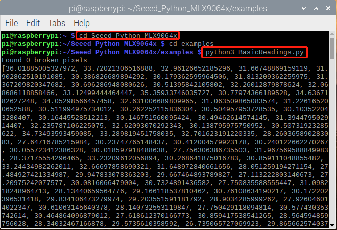
O resultado será exibido como acima se tudo correr bem.
Uma interface de usuário atualizada do resultado no Raspberry Pi foi lançada como a seguir:
- Passo 1 Instale o pyqt5:
sudo apt-get install python3-pyqt5 -y
- Passo 2 Instale a partir do PyPI:
sudo pip3 install seeed_python_ircamera
- Passo 3 Defina a velocidade máxima do i2c e depois reinicie:
sudo sh -c "echo dtparam=i2c_arm=on,i2c_arm_baudrate=400000 >> /boot/config.txt"
sudo reboot
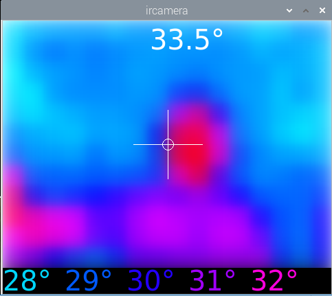
- Passo 4 Digite o comando abaixo no terminal:
sudo ircamera I2C MLX90641
O resultado será exibido como a seguir se tudo correr bem.
Recursos
- [PDF] Datasheet do MLX90641
- [ZIP] Visualização MLX90641
Suporte Técnico & Discussão de Produto
Envie qualquer problema técnico para o nosso fórum.
Atualizável para Sensores Industriais
Com o controlador S2110 e o data logger S2100 da SenseCAP, você pode facilmente transformar o Grove em um sensor LoRaWAN®. A Seeed não apenas ajuda você na prototipagem, mas também oferece a possibilidade de expandir seu projeto com a série SenseCAP de robustos sensores industriais.
A carcaça IP66, a configuração via Bluetooth, a compatibilidade com a rede global LoRaWAN®, a bateria interna de 19 Ah e o forte suporte do APP fazem do SenseCAP S210x a melhor escolha para aplicações industriais. A série inclui sensores para umidade do solo, temperatura e umidade do ar, intensidade de luz, CO2, EC e uma estação meteorológica 8 em 1. Experimente o mais recente SenseCAP S210x para o seu próximo projeto industrial de sucesso.