Desenvolver ambos os chips do SenseCAP Indicator com Arduino
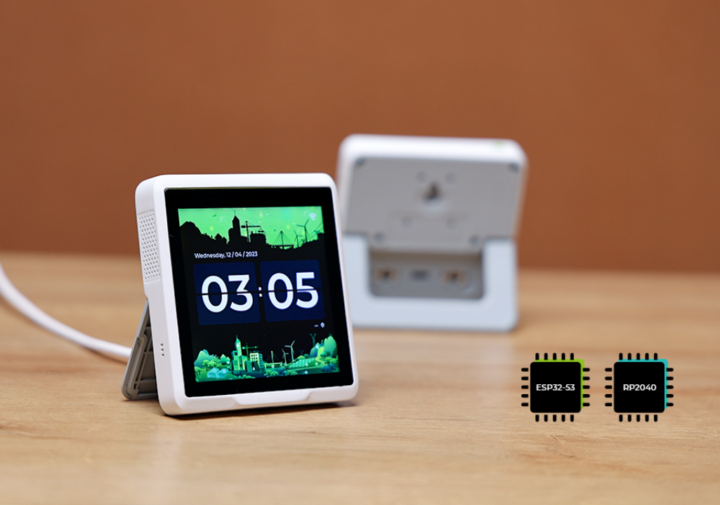
O SenseCAP Indicator é um dispositivo com tela sensível ao toque de 4 polegadas, alimentado por dois MCUs: ESP32 e RP2040. ESP32 e RP2040 são microcontroladores altamente capazes que oferecem uma variedade de recursos e funções.
Este tutorial irá guiá‑lo para desenvolver seu próprio projeto/firmware personalizado para o Sensecap Indicator usando a simplicidade e flexibilidade do framework Arduino.
Preparação de Hardware
Estou usando o SenseCAP Indicator como hardware aqui e há quatro tipos de sensores (CO2, Temp, Humi, TVOC) nele. O conteúdo aqui deve incluir:
| SenseCAP Indicator D1S |
|---|
 |
Visão Geral de Hardware e Conhecimentos de Desenvolvimento
O Indicator é projetado com dois MCUs, onde o RP2040 e o ESP32S3 trabalham ao mesmo tempo.
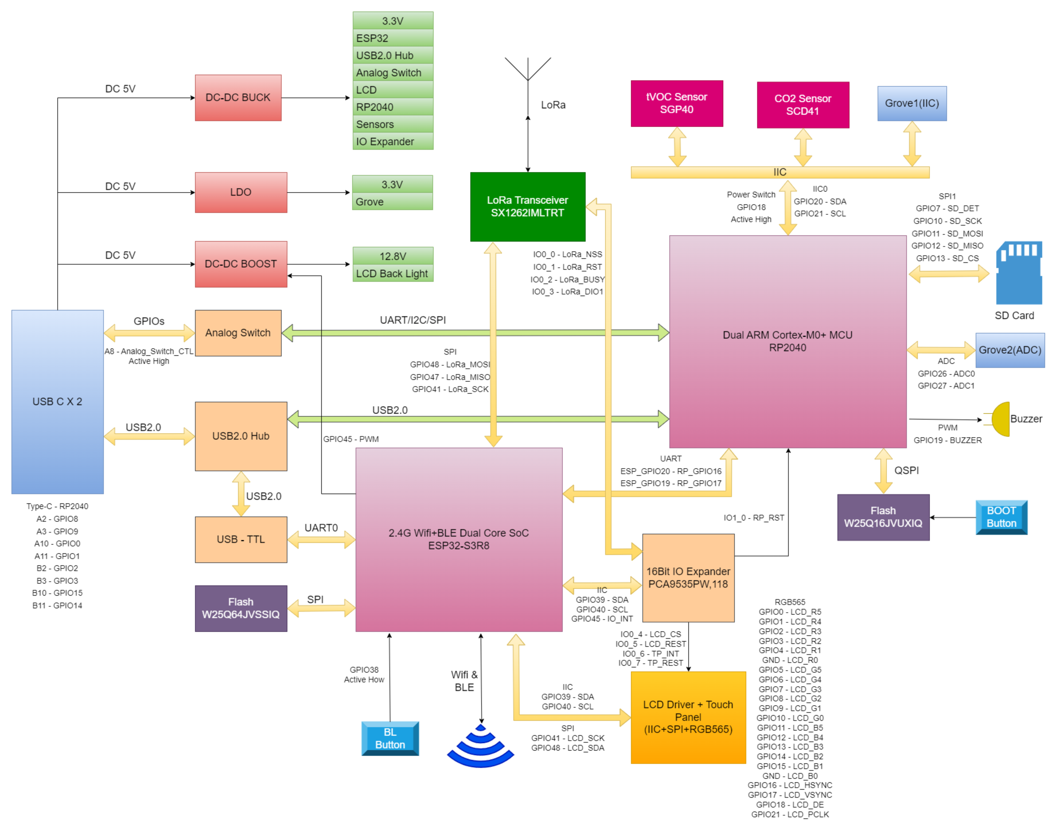
Com base no diagrama acima, sabemos que:
- Todos os sensores estão conectados ao microcontrolador RP2040 usando o protocolo I2C
- Há um módulo expansor de IO I2C usando o CI PCA9535
- A tela está conectada ao microcontrolador ESP32S3 com 2 pinos (CS, RESET) conectados ao expansor I2C PCA9535
- O RP2040 está conectado ao ESP32S3 via pino 20 e pino 19 no ESP32S3 usando interfaces UART
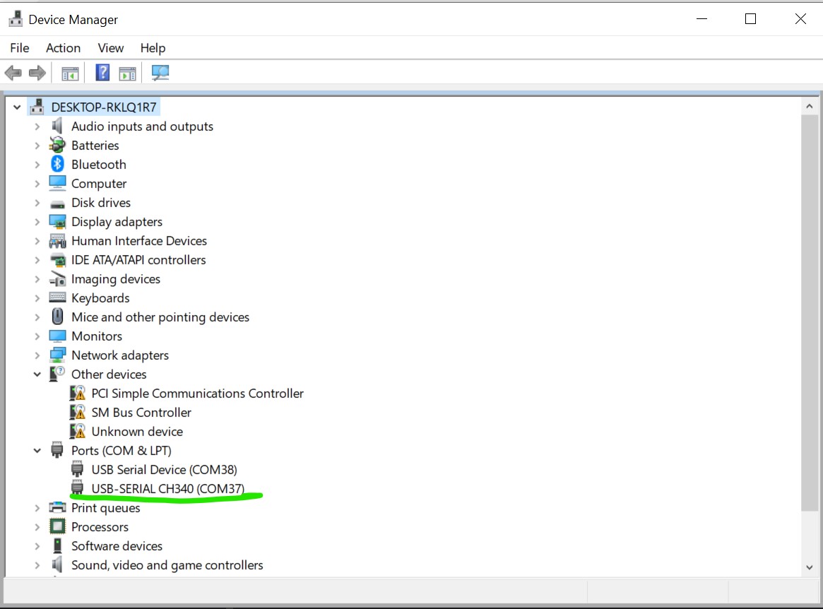
Assim, se o Sensecap Indicator for conectado ao computador, você verá 2 portas seriais: uma para o RP2040 e outra para o ESP32S3. A que contém a informação USB-SERIAL CH340 é a que está conectada ao ESP32S3, e será esta que usaremos para o restante do tutorial.
Preparação de Software
Estamos usando Arduino aqui.
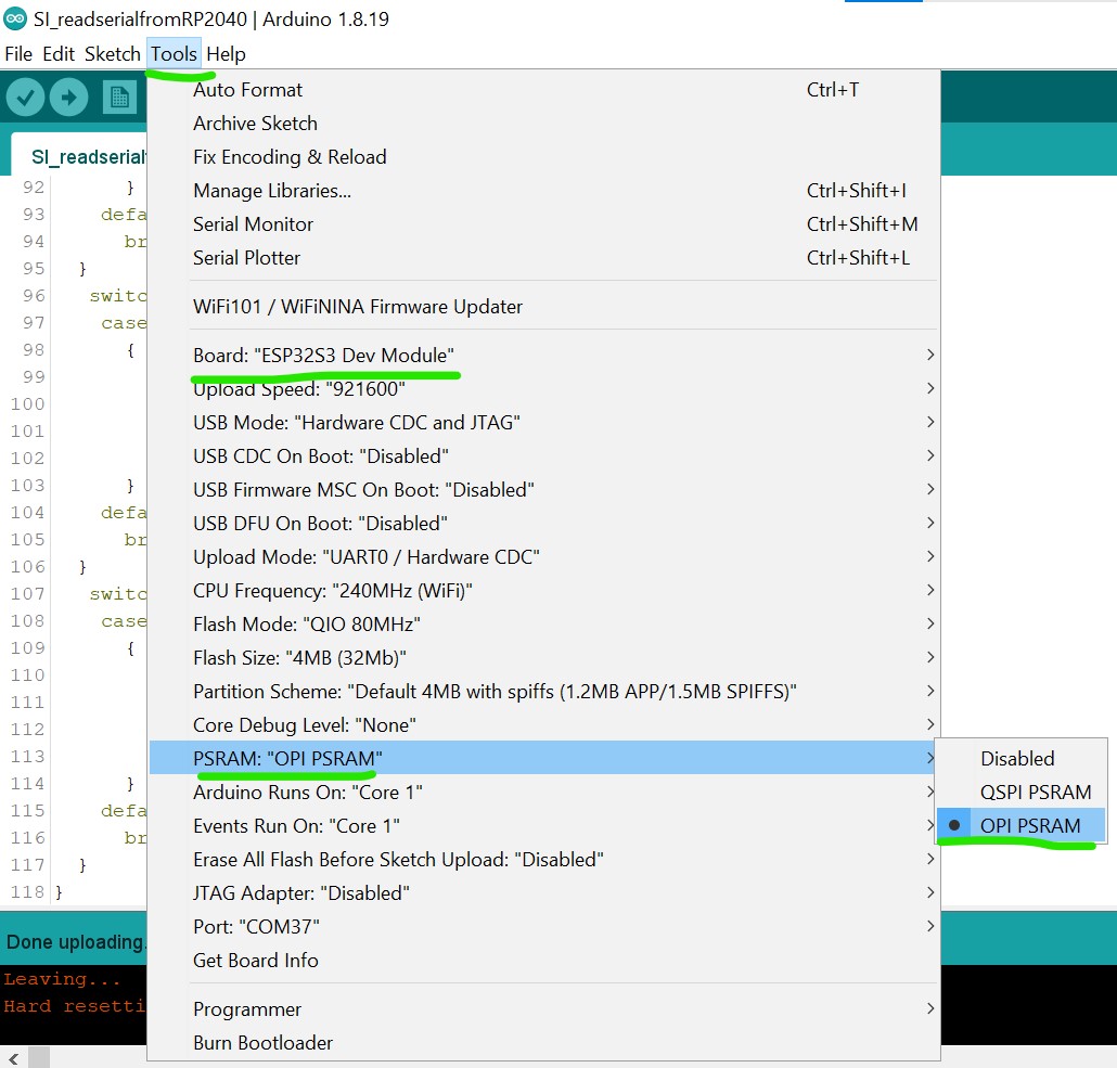
Antes de continuar com o tutorial, certifique‑se de que as seguintes etapas foram concluídas no Arduino IDE:
- Definição de placa ESP32: Certifique‑se de que a definição de placa ESP32 esteja instalada e atualizada para a versão mais recente. Você pode seguir este guia se a placa ESP32 ainda não estiver no Arduino IDE.
- Seleção de placa: Escolha ESP32S3 Dev Module como definição de placa.
- PSRAM: Ative a função OPI PSRAM no Arduino IDE para garantir o funcionamento adequado da tela.
Placas Utilizadas
Para garantir a compatibilidade com o projeto, utilize as seguintes versões de placas:
- ESP32: versão 3.1.2
- Raspberry Pi Pico Arduino: versão 4.4.3
Bibliotecas Utilizadas
TouchLib: versão 0.0.2
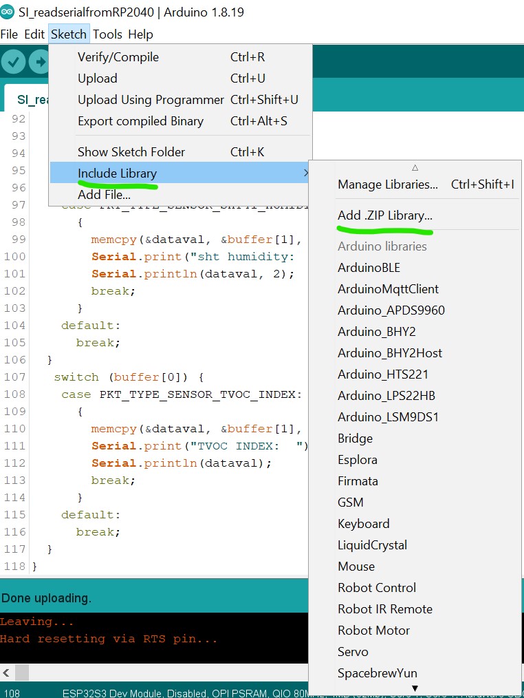
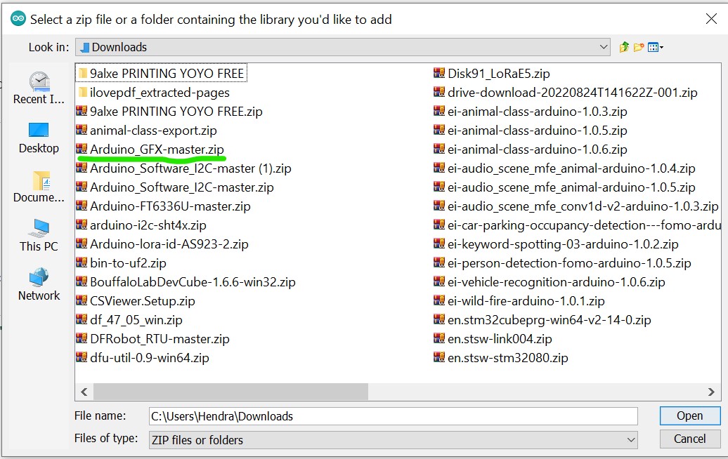
Para integrar o driver de toque e unificar a interface de toque, a biblioteca TouchLib é necessária. Ela não está disponível no Gerenciador de Bibliotecas do Arduino IDE. Você pode baixá‑la manualmente do repositório TouchLib no GitHub e, em seguida, adicioná‑la ao Arduino IDE via Sketch > Include Library > Add .ZIP Library.
Depois que a biblioteca for baixada, abra o Arduino IDE, vá ao menu Sketch, escolha "Add .ZIP Library" e então adicione a biblioteca baixada ao IDE.
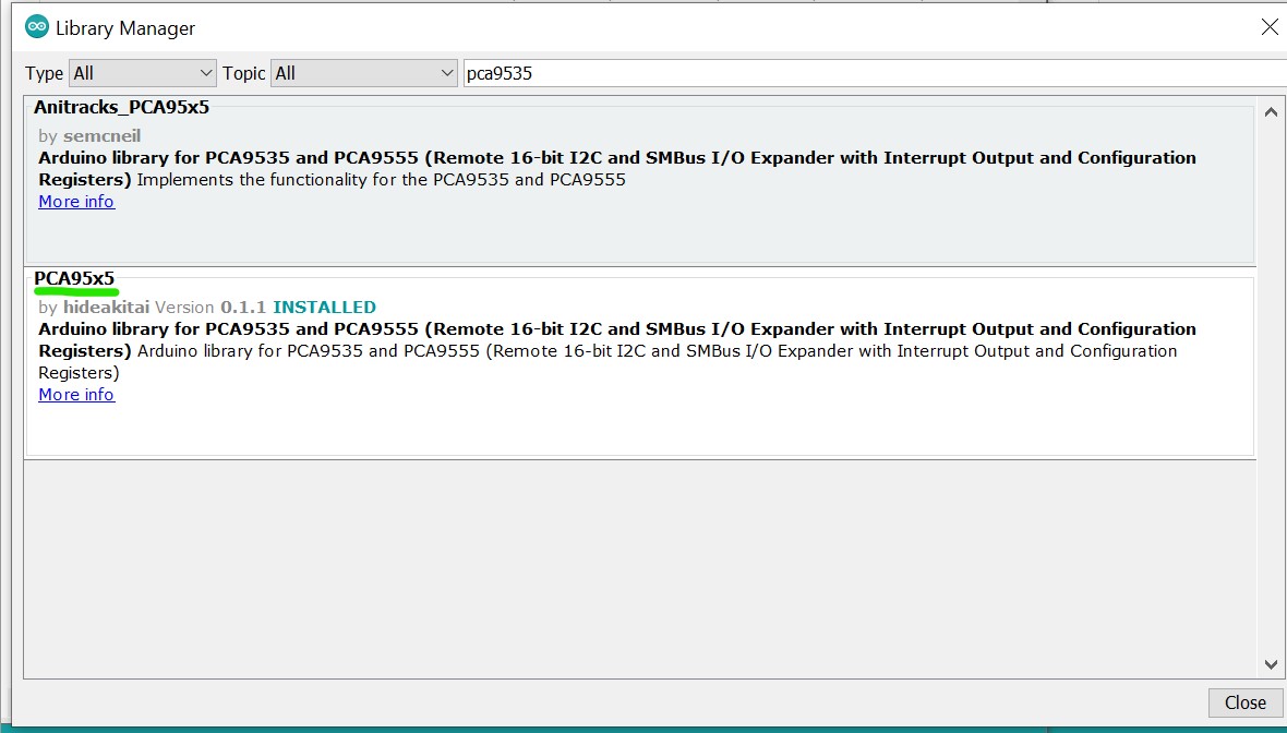
Da mesma forma, para uma integração suave, você precisa verificar o mesmo menu Sketch e selecionar "Manage Libraries", depois procurar as bibliotecas necessárias (por exemplo, "PCA9535", escolha a feita por hidea kitai) e instalá‑las, garantindo ao mesmo tempo as seguintes versões para todas as outras bibliotecas necessárias:
- Adafruit TinyUSB: versão 3.4.2
- Anitracks_PCA95x5: versão 0.1.3
- GFX Library for Arduino: versão 1.5.3
- PacketSerial: versão 1.4.0
- lvgl: versão 9.2.2
- PCA95x5: versão 0.1.3
Certifique‑se de que essas bibliotecas e placas estejam instaladas no Arduino IDE para evitar problemas de compatibilidade.
Primeiros Passos
- Novo Tutorial (por LongDirtyAnimAlf)
- Tutorial Antigo (por Hendra)
Depois que todas as bibliotecas necessárias forem instaladas, envie o código abaixo para testar se a tela está funcionando com o ambiente Arduino. Você pode enviar o código abaixo:
#include <Arduino_GFX_Library.h>
#include <PCA95x5.h>
#define GFX_BL DF_GFX_BL // default backlight pin, you may replace DF_GFX_BL to actual backlight pin

/* More dev device declaration: https://github.com/moononournation/Arduino_GFX/wiki/Dev-Device-Declaration */
#if defined(DISPLAY_DEV_KIT)
Arduino_GFX *gfx = create_default_Arduino_GFX();
#else /* !defined(DISPLAY_DEV_KIT) */

#define GFX_DEV_DEVICE ESP32_S3_RGB
#define GFX_BL 45
Arduino_DataBus *bus = new Arduino_SWSPI(
    GFX_NOT_DEFINED /* DC */, PCA95x5::Port::P04 /* CS */,
    41 /* SCK */, 48 /* MOSI */, GFX_NOT_DEFINED /* MISO */);

// option 1:
// Uncomment for 4" rect display
Arduino_ESP32RGBPanel *rgbpanel = new Arduino_ESP32RGBPanel(
    18 /* DE */, 17 /* VSYNC */, 16 /* HSYNC */, 21 /* PCLK */,
    4 /* R0 */, 3 /* R1 */, 2 /* R2 */, 1 /* R3 */, 0 /* R4 */,
    10 /* G0 */, 9 /* G1 */, 8 /* G2 */, 7 /* G3 */, 6 /* G4 */, 5 /* G5 */,
    15 /* B0 */, 14 /* B1 */, 13 /* B2 */, 12 /* B3 */, 11 /* B4 */,
    1 /* hsync_polarity */, 10 /* hsync_front_porch */, 8 /* hsync_pulse_width */, 50 /* hsync_back_porch */,
    1 /* vsync_polarity */, 10 /* vsync_front_porch */, 8 /* vsync_pulse_width */, 20 /* vsync_back_porch */);
Arduino_RGB_Display *gfx = new Arduino_RGB_Display(
    480 /* width */, 480 /* height */, rgbpanel, 2 /* rotation */, true /* auto_flush */,
    bus, GFX_NOT_DEFINED /* RST */, st7701_type1_init_operations, sizeof(st7701_type1_init_operations));

#endif /* !defined(DISPLAY_DEV_KIT) */
/*******************************************************************************
 * End of Arduino_GFX setting
 ******************************************************************************/

void setup(void)
{
  Serial.begin(115200);
  // Serial.setDebugOutput(true);
  // while(!Serial);
  Serial.println("Arduino_GFX Hello World example");

#ifdef GFX_EXTRA_PRE_INIT
  GFX_EXTRA_PRE_INIT();
#endif

  // Init Display
  if (!gfx->begin())
  {
    Serial.println("gfx->begin() failed!");
  }
  gfx->fillScreen(BLACK);

#ifdef GFX_BL
  pinMode(GFX_BL, OUTPUT);
  digitalWrite(GFX_BL, HIGH);
#endif

  gfx->setCursor(10, 10);
  gfx->setTextColor(RED);
  gfx->println("Sensecap Indicator");

  delay(5000); // 5 seconds
}

void loop()
{
  gfx->setCursor(random(gfx->width()), random(gfx->height()));
  gfx->setTextColor(random(0xffff), random(0xffff));
  gfx->setTextSize(random(6) /* x scale */, random(6) /* y scale */, random(2) /* pixel_margin */);
  gfx->println("Sensecap Indicator");

  delay(1000); // 1 second
}
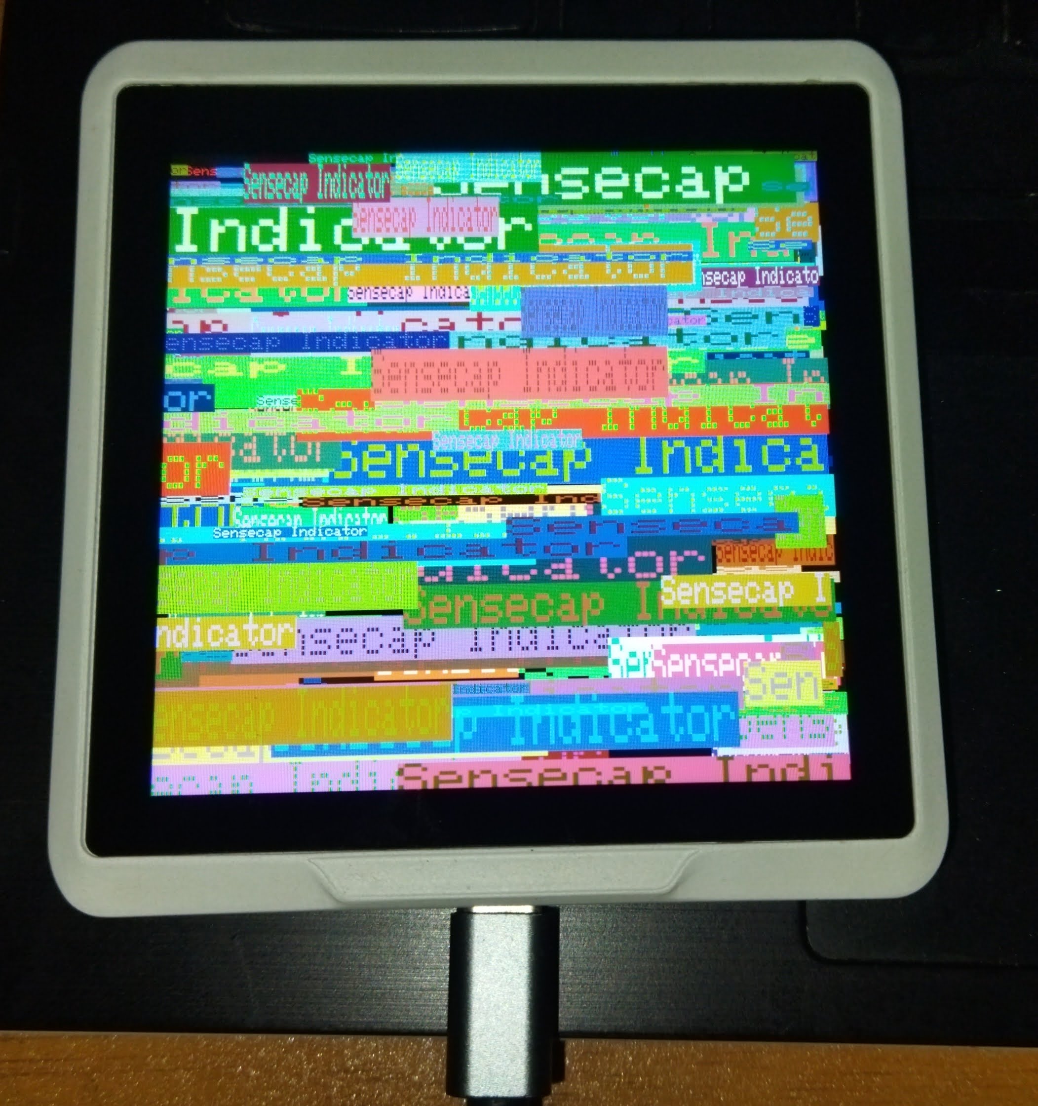
Se tudo correr bem, um texto "Sensecap Indicator" será exibido aleatoriamente na tela.
Criando Aplicativos GUI Simples com o SenseCap Indicator
O SenseCap Indicator possui um poderoso microcontrolador ESP32-S3 e uma tela de alta resolução 480x480, o que o torna ideal para criar interfaces gráficas de usuário. Agora, continuaremos nosso desenvolvimento com o SenseCap Indicator explorando como criar aplicativos GUI interativos usando LVGL. Você pode baixar o projeto completo, incluindo código‑fonte e arquivos de cabeçalho, a partir do repositório: Download SenseCap Indicator LVGL Project
Após baixar e extrair os arquivos do projeto, envie o código a seguir para criar um aplicativo GUI básico com múltiplas telas:
/*Using LVGL with Arduino requires some extra steps:
 *Be sure to read the docs here: https://docs.lvgl.io/master/get-started/platforms/arduino.html
 Install: lvgl*/

// This define is sometimes missing when using old ESP32-IDF version
//#define ESP_INTR_CPU_AFFINITY_AUTO 0

#include <Arduino.h>
#include <lvgl.h>
#include <Arduino_GFX_Library.h>
#include <PacketSerial.h>
#include "Indicator_Extender.h"
#include "Indicator_SWSPI.h"
#include "ui.h"
#include "touch.h"

#define HOR_RES 480
#define VER_RES 480

#define PACKET_UART_RXD 20
#define PACKET_UART_TXD 19

#define BUTTON_PIN 38

#define GFX_DEV_DEVICE ESP32_S3_RGB
#define RGB_PANEL
#define GFX_BL 45
Arduino_DataBus *bus = new Indicator_SWSPI(
    GFX_NOT_DEFINED /* DC */, EXPANDER_IO_LCD_CS /* CS */,
    SPI_SCLK /* SCK */, SPI_MOSI /* MOSI */, GFX_NOT_DEFINED /* MISO */);

Arduino_ESP32RGBPanel *rgbpanel = new Arduino_ESP32RGBPanel(
    18 /* DE */, 17 /* VSYNC */, 16 /* HSYNC */, 21 /* PCLK */,
    4 /* R0 */, 3 /* R1 */, 2 /* R2 */, 1 /* R3 */, 0 /* R4 */,
    10 /* G0 */, 9 /* G1 */, 8 /* G2 */, 7 /* G3 */, 6 /* G4 */, 5 /* G5 */,
    15 /* B0 */, 14 /* B1 */, 13 /* B2 */, 12 /* B3 */, 11 /* B4 */,
    1 /* hsync_polarity */, 10 /* hsync_front_porch */, 8 /* hsync_pulse_width */, 50 /* hsync_back_porch */,
    1 /* vsync_polarity */, 10 /* vsync_front_porch */, 8 /* vsync_pulse_width */, 20 /* vsync_back_porch */);
Arduino_RGB_Display *gfx = new Arduino_RGB_Display(
    HOR_RES /* width */, VER_RES /* height */, rgbpanel, 0 /* rotation */, false /* auto_flush */,
    bus, GFX_NOT_DEFINED /* RST */, st7701_indicator_init_operations, sizeof(st7701_indicator_init_operations));


COBSPacketSerial myPacketSerial;

void onPacketReceived(const uint8_t* buffer, size_t size);

uint32_t millis_cb(void)
{
  return millis();
}

/*Read the touchpad*/
void my_touchpad_read(lv_indev_t *indev, lv_indev_data_t *data)
{
  if (touch_has_signal())
  {
    if (touch_touched())
    {
      data->state = LV_INDEV_STATE_PRESSED;

      /*Set the coordinates*/
      data->point.x = touch_last_x;
      data->point.y = touch_last_y;
    }
    else if (touch_released())
    {
      data->state = LV_INDEV_STATE_RELEASED;
    }
  }
  else
  {
    data->state = LV_INDEV_STATE_RELEASED;
  }
}

// Main buttons event handler
static void event_handler(lv_event_t * e)
{
  lv_event_code_t code = lv_event_get_code(e);
  lv_obj_t * btn = lv_event_get_current_target_obj(e);

  if (btn != NULL)
  {
    if(code == LV_EVENT_CLICKED)
    {
      void * btn_no_void = (void*)lv_event_get_user_data(e);
      byte btn_no = (byte)((uintptr_t)btn_no_void);
      lv_obj_t * screen = lv_obj_get_screen(btn);
      if (screen != NULL)
      {
        Serial.println("Screen assigned");
        if (screen == screen2)
        {
          Serial.println("Screen 2");
          if (btn_no != 0)
          {
            Create_Screen3(event_handler);
            lv_screen_load(screen3);
          }
        }
        if (screen == screen3)
        {
          Serial.println("Screen 3");
          if (btn_no == 0)
          {
            lv_screen_load(screen2);
            lv_obj_delete(screen3);
          }
        }
      }
    }
  }
}

void setup()
{
  Serial.begin(115200);
  Serial.println("SenseCap Indicator startup");
  String LVGL_Arduino = String('V') + lv_version_major() + "." + lv_version_minor() + "." + lv_version_patch();
  Serial.println(LVGL_Arduino);

  pinMode(BUTTON_PIN, INPUT);

  // Init Indicator hardware
  extender_init();

  myPacketSerial.begin(115200);
  Serial1.begin(115200, SERIAL_8N1, PACKET_UART_RXD, PACKET_UART_TXD);
  myPacketSerial.setStream(&Serial1);
  myPacketSerial.setPacketHandler(&onPacketReceived);

  // Init Display
  if (!gfx->begin(12000000L))
  {
    Serial.println("gfx->begin() failed!");
    Serial.println("Expect sever errors !!!");
  }
  gfx->fillScreen(RGB565_BLACK);

#ifdef GFX_BL
  pinMode(GFX_BL, OUTPUT);
  digitalWrite(GFX_BL, HIGH);
#endif
  lv_init();

  /*Set a tick source so that LVGL will know how much time elapsed. */
  lv_tick_set_cb(millis_cb);

  /* register print function for debugging */
#if LV_USE_LOG != 0
  lv_log_register_print_cb(my_print);
#endif

  lv_screen_init(gfx, HOR_RES, VER_RES);
  //lv_display_set_rotation(disp, LV_DISPLAY_ROTATION_0);
  //lv_display_set_antialiasing(disp,false);

  // Init touch device
  touch_init(HOR_RES, VER_RES, 0); // rotation will be handled by lvgl
  /*Initialize the input device driver*/
  lv_indev_t *indev = lv_indev_create();
  lv_indev_set_type(indev, LV_INDEV_TYPE_POINTER); /*Touchpad should have POINTER type*/
  lv_indev_set_read_cb(indev, my_touchpad_read);

  Screen2Create(event_handler);

  lv_screen_load(screen2);

  Serial.println("Setup done");
}

void loop()
{
  static TickType_t xLastWakeTime = xTaskGetTickCount();

  /*
  unsigned long startTime = millis();
  while (digitalRead(BUTTON_PIN) == LOW)
  {
    if (millis() - startTime >= 10000)
    {
      ESP.restart();
      //esp_restart();
    }
  }
  */

  myPacketSerial.update();
  // Check for a receive buffer overflow (optional).
  if (myPacketSerial.overflow())
  {
    // Send an alert via a pin (e.g. make an overflow LED) or return a
    // user-defined packet to the sender.
  }

  lv_task_handler(); /* let the GUI do its work */

  // Simple delay always 5ms
  //delay(5);

  // This delay will adapt to the time consumed in the above tasks
  // If these tasks consume time, it will delay shorter
  vTaskDelayUntil( &xLastWakeTime, ( 5 / portTICK_PERIOD_MS ) );
}

void onPacketReceived(const uint8_t* buffer, size_t size)
{
  if (size < 1) {
    return;
  }

  byte index = 0;
  byte Command = buffer[index++];
  if (Command == 0x55)
  {
    long Temperature = 0;
    long Humidity = 0;

    memcpy(&Temperature, &buffer[index], sizeof(Temperature));
    index += sizeof(Temperature);
    memcpy(&Humidity, &buffer[index], sizeof(Humidity));
    index += sizeof(Humidity);

    Screen2AddData(Temperature,Humidity);
  }
}
Depois de enviar o código, abra o Serial Monitor e defina a taxa de baud para 115200. Você deverá ver mensagens de inicialização e sua GUI aparecerá na tela, mostrando a Screen2 com quaisquer dados de temperatura e umidade recebidos através da conexão UART.
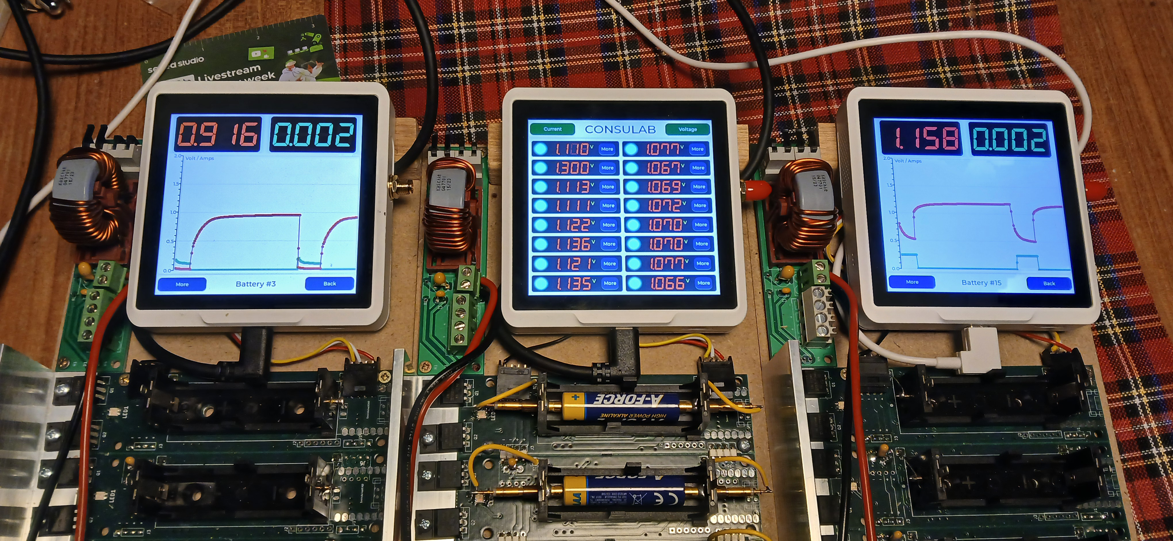
Aplicativo de GUI Avançado com Múltiplas Telas e Visualização de Dados
O segundo exemplo se baseia no aplicativo básico adicionando recursos mais sofisticados, incluindo monitoramento de bateria, visualização dinâmica de dados e indicadores de status com codificação por cores. Você pode baixar o projeto completo, incluindo código‑fonte e arquivos de cabeçalho, a partir do repositório: Download SenseCap Indicator LVGL Project
Para implementar esta versão, envie o seguinte código:
/*Using LVGL with Arduino requires some extra steps:
 *Be sure to read the docs here: https://docs.lvgl.io/master/get-started/platforms/arduino.html
 Install: lvgl*/

// This define is sometimes missing when using old ESP32-IDF version
//#define ESP_INTR_CPU_AFFINITY_AUTO 0

#include <Arduino.h>
#include <lvgl.h>
#include <Arduino_GFX_Library.h>
#include <PacketSerial.h>
#include "Indicator_Extender.h"
#include "Indicator_SWSPI.h"
#include "ui.h"
#include "touch.h"
#include "shared.h"

#define HOR_RES 480
#define VER_RES 480

#define PACKET_UART_RXD 20
#define PACKET_UART_TXD 19

#define BUTTON_PIN 38

#define GFX_DEV_DEVICE ESP32_S3_RGB
#define RGB_PANEL
#define GFX_BL 45
Arduino_DataBus *bus = new Indicator_SWSPI(
    GFX_NOT_DEFINED /* DC */, EXPANDER_IO_LCD_CS /* CS */,
    SPI_SCLK /* SCK */, SPI_MOSI /* MOSI */, GFX_NOT_DEFINED /* MISO */);

Arduino_ESP32RGBPanel *rgbpanel = new Arduino_ESP32RGBPanel(
    18 /* DE */, 17 /* VSYNC */, 16 /* HSYNC */, 21 /* PCLK */,
    4 /* R0 */, 3 /* R1 */, 2 /* R2 */, 1 /* R3 */, 0 /* R4 */,
    10 /* G0 */, 9 /* G1 */, 8 /* G2 */, 7 /* G3 */, 6 /* G4 */, 5 /* G5 */,
    15 /* B0 */, 14 /* B1 */, 13 /* B2 */, 12 /* B3 */, 11 /* B4 */,
    1 /* hsync_polarity */, 10 /* hsync_front_porch */, 8 /* hsync_pulse_width */, 50 /* hsync_back_porch */,
    1 /* vsync_polarity */, 10 /* vsync_front_porch */, 8 /* vsync_pulse_width */, 20 /* vsync_back_porch */);
Arduino_RGB_Display *gfx = new Arduino_RGB_Display(
    HOR_RES /* width */, VER_RES /* height */, rgbpanel, 0 /* rotation */, false /* auto_flush */,
    bus, GFX_NOT_DEFINED /* RST */, st7701_indicator_init_operations, sizeof(st7701_indicator_init_operations));

TBatteryBoard BatteryBoards[DAUGHTERBOARDCOUNT] = {0};

COBSPacketSerial myPacketSerial;
//PacketSerial_<COBS, 0, 1024> myPacketSerial;

void onPacketReceived(const uint8_t* buffer, size_t size);

#if LV_USE_LOG != 0
void my_print(lv_log_level_t level, const char *buf)
{
  LV_UNUSED(level);
  Serial.println(buf);
  Serial.flush();
}
#endif

uint32_t millis_cb(void)
{
  return millis();
}

/*Read the touchpad*/
void my_touchpad_read(lv_indev_t *indev, lv_indev_data_t *data)
{
  if (touch_has_signal())
  {
    if (touch_touched())
    {
      data->state = LV_INDEV_STATE_PRESSED;

      /*Set the coordinates*/
      data->point.x = touch_last_x;
      data->point.y = touch_last_y;
    }
    else if (touch_released())
    {
      data->state = LV_INDEV_STATE_RELEASED;
    }
  }
  else
  {
    data->state = LV_INDEV_STATE_RELEASED;
  }
}

static void event_handler(lv_event_t * e)
{
  lv_event_code_t code = lv_event_get_code(e);
  lv_obj_t * btn = lv_event_get_current_target_obj(e);

  if (btn != NULL)
  {
    if(code == LV_EVENT_CLICKED)
    {
      void * btn_no_void = (void*)lv_event_get_user_data(e);
      byte btn_no = (byte)((uintptr_t)btn_no_void);
      lv_obj_t * screen = lv_obj_get_screen(btn);
      if (screen != NULL)
      {
        Serial.println("Screen assigned");

        if (screen == screen1)
        {
          Serial.println("Screen 1");
          Screen2SetActive(btn_no);
          lv_screen_load(screen2);
          //Screen2SetActive(5);
        }
        if (screen == screen2)
        {
          Serial.println("Screen 2");
          if (btn_no == 0)
          {
            lv_screen_load(screen1);
          }
          else
          {
            Create_Screen3(event_handler);
            lv_screen_load(screen3);
          }
        }
        if (screen == screen3)
        {
          Serial.println("Screen 3");
          if (btn_no == 0)
          {
            lv_screen_load(screen2);
            lv_obj_delete(screen3);
          }
        }
      }
    }
  }
}

void setup()
{
  Serial.begin(115200);
  // Serial.setDebugOutput(true);
  // while(!Serial);
  Serial.println("SenseCap Indicator startup");
  String LVGL_Arduino = String('V') + lv_version_major() + "." + lv_version_minor() + "." + lv_version_patch();
  Serial.println(LVGL_Arduino);

  pinMode(BUTTON_PIN, INPUT);

  // Init Indicator hardware
  extender_init();

  myPacketSerial.begin(115200);
  Serial1.begin(115200, SERIAL_8N1, PACKET_UART_RXD, PACKET_UART_TXD);
  myPacketSerial.setStream(&Serial1);
  myPacketSerial.setPacketHandler(&onPacketReceived);

  // Init Display
  if (!gfx->begin(12000000L))
  {
    Serial.println("gfx->begin() failed!");
    Serial.println("Expect sever errors !!!");
  }
  gfx->fillScreen(RGB565_BLACK);

#ifdef GFX_BL
  pinMode(GFX_BL, OUTPUT);
  digitalWrite(GFX_BL, HIGH);
#endif
  lv_init();

  /*Set a tick source so that LVGL will know how much time elapsed. */
  lv_tick_set_cb(millis_cb);

  /* register print function for debugging */
#if LV_USE_LOG != 0
  lv_log_register_print_cb(my_print);
#endif

  lv_screen_init(gfx, HOR_RES, VER_RES);
  //lv_display_set_rotation(disp, LV_DISPLAY_ROTATION_0);
  //lv_display_set_antialiasing(disp,false);

  // Init touch device
  touch_init(HOR_RES, VER_RES, 0); // rotation will be handled by lvgl
  /*Initialize the input device driver*/
  lv_indev_t *indev = lv_indev_create();
  lv_indev_set_type(indev, LV_INDEV_TYPE_POINTER); /*Touchpad should have POINTER type*/
  lv_indev_set_read_cb(indev, my_touchpad_read);

  Create_Screen1(event_handler);

  Screen2Create(event_handler);
  Screen2InitData();

  lv_screen_load(screen1);

  Serial.println("Setup done");
}

void loop()
{
  static TickType_t xLastWakeTime = xTaskGetTickCount();

  /*
  unsigned long startTime = millis();
  while (digitalRead(BUTTON_PIN) == LOW)
  {
    if (millis() - startTime >= 10000)
    {
      ESP.restart();
      //esp_restart();
    }
  }
  */

  myPacketSerial.update();
  // Check for a receive buffer overflow (optional).
  if (myPacketSerial.overflow())
  {
    // Send an alert via a pin (e.g. make an overflow LED) or return a
    // user-defined packet to the sender.
  }

  lv_task_handler(); /* let the GUI do its work */

  // Simple delay always 5ms
  //delay(5);

  // This delay will adapt to the time consumed in the above tasks
  // If these tasks consume time, it will delay shorter
  vTaskDelayUntil( &xLastWakeTime, ( 5 / portTICK_PERIOD_MS ) );
}

void onPacketReceived(const uint8_t* buffer, size_t size)
{
#ifndef YOLO
  Serial.printf("<--- recv len:%d, data: ", size);
  for (int i = 0; i < size; i++) {
    Serial.printf("0x%x ", buffer[i]);
  }
  Serial.println("");
#endif


  if (size < 1) {
    return;
  }

  byte index = 0;

  TCommands Command = (TCommands)buffer[index++];

  if ((Command == CMD_get_data) || (Command == CMD_set_value))
  {
    byte BatteryNumber = buffer[index++];

    if (Command == CMD_get_data)
    {
      dword tempcalc;
      word Volt = 0;
      word Amps = 0;

      memcpy(&Volt, &buffer[index], 2);
      index += 2;
      memcpy(&Amps, &buffer[index], 2);
      index += 2;

      Screen2AddData((BatteryNumber+1),Volt,Amps);

      // Put data on screen 1
      tempcalc = Volt * 3300u;
      tempcalc /= (dword)((1u << BITS)-1u);
      SetVoltageScreen1mV(BatteryNumber,(word)tempcalc);

      tempcalc = Amps * 6000u;
      tempcalc /= (dword)((1u << BITS)-1u);
      SetCurrentScreen1mA(BatteryNumber,(word)tempcalc);
    }

    if (Command == CMD_set_value)
    {
      lv_color_t c = LV_COLOR_MAKE(0,0,0);
      TBatteryStatus Status = (TBatteryStatus)buffer[index++];
      switch (Status)
      {
        case BSCurrent:
        case BSPower:
        case BSResistor:
        {
          c = lv_palette_main(LV_PALETTE_DEEP_ORANGE);
          break;
        }
        case BSCharge:
        case BSVoltage:
        case BSPulse:
        {
          c = lv_palette_main(LV_PALETTE_PURPLE);
          break;
        }
        case BSOff:
        {
          c = LV_COLOR_MAKE(0X00,0xFF,0xFF);
          break;
        }
        default:
        {
          c = lv_palette_main(LV_PALETTE_YELLOW);
        }
      }
      SetLedScreen1(BatteryNumber,c);
    }
  }
}
Com este código, o SenseCap Indicator exibirá um aplicativo com três telas. A Screen1 mostra uma visão geral dos dados da bateria com indicadores de status codificados por cores, a Screen2 fornece informações detalhadas para baterias individuais e a Screen3 oferece controles ou informações adicionais.
Agora podemos desenvolver com a tela que conecta o chip ESP32S3 e lê os sensores que se ligam ao chip RP2040. Por fim, combinamos ambos.
Desenvolver com uma Tela Conectada ao Chip ESP32-S3
O Sensecap Indicator está usando o módulo ST7701 para a tela e ele utiliza interfaces paralelas e já está conectado aos pinos no MCU ESP32S3. Para poder controlar a tela, é necessária uma biblioteca arduino. Você pode baixar aqui
Após baixar a biblioteca, abra o Arduino e, no menu Sketch, escolha add zip library
Adicione a biblioteca baixada na IDE do Arduino.
Enquanto isso, você precisa verificar o mesmo menu Sketch e escolher "manage libraries", depois procurar por "PCA9535" e selecionar a feita por hidea kitai e instalá-la.
A biblioteca PCA9535 é necessária porque o pino CS do ST7701 está conectado ao módulo expansor i2c PCA9535. Especificamente ao pino 4 do módulo i2c.
Depois que todas as bibliotecas necessárias estiverem instaladas, carregue o código abaixo para testar se a tela está funcionando com o ambiente Arduino. Você pode carregar o código abaixo:
#include <Arduino_GFX_Library.h>
#include <PCA95x5.h>
#define GFX_BL DF_GFX_BL // default backlight pin, you may replace DF_GFX_BL to actual backlight pin

/* More dev device declaration: https://github.com/moononournation/Arduino_GFX/wiki/Dev-Device-Declaration */
#if defined(DISPLAY_DEV_KIT)
Arduino_GFX *gfx = create_default_Arduino_GFX();
#else /* !defined(DISPLAY_DEV_KIT) */

#define GFX_DEV_DEVICE ESP32_S3_RGB
#define GFX_BL 45
Arduino_DataBus *bus = new Arduino_SWSPI(
    GFX_NOT_DEFINED /* DC */, PCA95x5::Port::P04 /* CS */,
    41 /* SCK */, 48 /* MOSI */, GFX_NOT_DEFINED /* MISO */);

// option 1:
// Uncomment for 4" rect display
Arduino_ESP32RGBPanel *rgbpanel = new Arduino_ESP32RGBPanel(
    18 /* DE */, 17 /* VSYNC */, 16 /* HSYNC */, 21 /* PCLK */,
    4 /* R0 */, 3 /* R1 */, 2 /* R2 */, 1 /* R3 */, 0 /* R4 */,
    10 /* G0 */, 9 /* G1 */, 8 /* G2 */, 7 /* G3 */, 6 /* G4 */, 5 /* G5 */,
    15 /* B0 */, 14 /* B1 */, 13 /* B2 */, 12 /* B3 */, 11 /* B4 */,
    1 /* hsync_polarity */, 10 /* hsync_front_porch */, 8 /* hsync_pulse_width */, 50 /* hsync_back_porch */,
    1 /* vsync_polarity */, 10 /* vsync_front_porch */, 8 /* vsync_pulse_width */, 20 /* vsync_back_porch */);
Arduino_RGB_Display *gfx = new Arduino_RGB_Display(
    480 /* width */, 480 /* height */, rgbpanel, 2 /* rotation */, true /* auto_flush */,
    bus, GFX_NOT_DEFINED /* RST */, st7701_type1_init_operations, sizeof(st7701_type1_init_operations));

#endif /* !defined(DISPLAY_DEV_KIT) */
/*******************************************************************************
 * End of Arduino_GFX setting
 ******************************************************************************/

void setup(void)
{
  Serial.begin(115200);
  // Serial.setDebugOutput(true);
  // while(!Serial);
  Serial.println("Arduino_GFX Hello World example");

#ifdef GFX_EXTRA_PRE_INIT
  GFX_EXTRA_PRE_INIT();
#endif

  // Init Display
  if (!gfx->begin())
  {
    Serial.println("gfx->begin() failed!");
  }
  gfx->fillScreen(BLACK);

#ifdef GFX_BL
  pinMode(GFX_BL, OUTPUT);
  digitalWrite(GFX_BL, HIGH);
#endif

  gfx->setCursor(10, 10);
  gfx->setTextColor(RED);
  gfx->println("Sensecap Indicator");

  delay(5000); // 5 seconds
}

void loop()
{
  gfx->setCursor(random(gfx->width()), random(gfx->height()));
  gfx->setTextColor(random(0xffff), random(0xffff));
  gfx->setTextSize(random(6) /* x scale */, random(6) /* y scale */, random(2) /* pixel_margin */);
  gfx->println("Sensecap Indicator");

  delay(1000); // 1 second
}
Se tudo correr bem, um texto "Sensecap Indicator" será exibido aleatoriamente na tela.
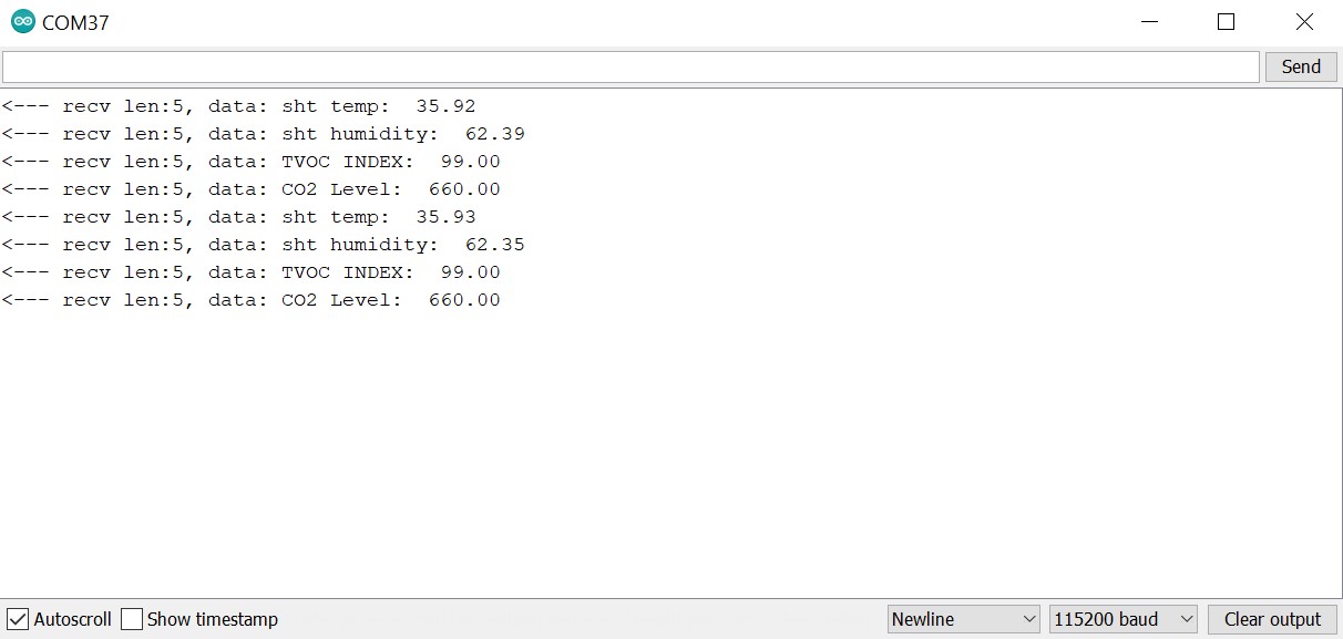
Ler os sensores que estão ligados ao chip RP2040
Conforme mencionado acima na seção de preparação, todos os sensores estão conectados ao RP2040. Supondo que você ainda tenha o firmware padrão no RP2040, os dados dos sensores são enviados para o ESP32S3 usando a interface UART.
Para que o ESP32S3 possa ler os dados, é necessário instalar uma biblioteca chamada PacketSerial.
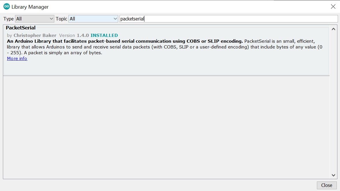
Depois que a biblioteca estiver instalada, você pode carregar o código abaixo para obter os dados dos sensores no ESP32S3:
//
// Copyright (c) 2012 Christopher Baker <https://christopherbaker.net>
//
// SPDX-License-Identifier: MIT
//


#include <PacketSerial.h>

PacketSerial myPacketSerial;

#define RXD2 20
#define TXD2 19

#define PKT_TYPE_SENSOR_SCD41_CO2 0XB2
#define PKT_TYPE_SENSOR_SHT41_TEMP 0XB3
#define PKT_TYPE_SENSOR_SHT41_HUMIDITY 0XB4
#define PKT_TYPE_SENSOR_TVOC_INDEX 0XB5
#define DEBUG   0

void setup()
{
  // We begin communication with our PacketSerial object by setting the
  // communication speed in bits / second (baud).
  myPacketSerial.begin(115200);

  // If we want to receive packets, we must specify a packet handler function.
  // The packet handler is a custom function with a signature like the
  // onPacketReceived function below.

  Serial1.begin(115200, SERIAL_8N1, RXD2, TXD2);
  myPacketSerial.setStream(&Serial1);
  myPacketSerial.setPacketHandler(&onPacketReceived);
}


void loop()
{
  // Do your program-specific loop() work here as usual.

  // The PacketSerial::update() method attempts to read in any incoming serial
  // data and emits received and decoded packets via the packet handler
  // function specified by the user in the void setup() function.
  //
  // The PacketSerial::update() method should be called once per loop(). Failure
  // to call the PacketSerial::update() frequently enough may result in buffer
  // serial overflows.
  myPacketSerial.update();

  // Check for a receive buffer overflow (optional).
  if (myPacketSerial.overflow())
  {
    // Send an alert via a pin (e.g. make an overflow LED) or return a
    // user-defined packet to the sender.
    //
    // Ultimately you may need to just increase your recieve buffer via the
    // template parameters (see the README.md).
  }
}


void onPacketReceived(const uint8_t *buffer, size_t size) {


  Serial.printf("<--- recv len:%d, data: ", size);


  if (size < 1) {
    return;
  }
  //byte serbytes[] = buffer[i];
  float dataval;
  switch (buffer[0]) {
    case PKT_TYPE_SENSOR_SCD41_CO2:
      {
        memcpy(&dataval, &buffer[1], sizeof(float));
        Serial.print("CO2 Level:  ");
        Serial.println(dataval);
        break;
      }
    default:
      break;
  }
   switch (buffer[0]) {
    case PKT_TYPE_SENSOR_SHT41_TEMP:
      {
        memcpy(&dataval, &buffer[1], sizeof(float));
        Serial.print("sht temp:  ");
        Serial.println(dataval, 2);
        break;
      }
    default:
      break;
  }
   switch (buffer[0]) {
    case PKT_TYPE_SENSOR_SHT41_HUMIDITY:
      {
        memcpy(&dataval, &buffer[1], sizeof(float));
        Serial.print("sht humidity:  ");
        Serial.println(dataval, 2);
        break;
      }
    default:
      break;
  }
   switch (buffer[0]) {
    case PKT_TYPE_SENSOR_TVOC_INDEX:
      {
        memcpy(&dataval, &buffer[1], sizeof(float));
        Serial.print("TVOC INDEX:  ");
        Serial.println(dataval);
        break;
      }
    default:
      break;
  }
}
Clique e abra o Serial Monitor e defina o Baud Rate para 115200, então você verá os dados dos sensores vindos do RP2040.
Combine dois exemplos e exiba os dados dos sensores na tela
Abra o menu de exemplos na IDE do Arduino e vá até GFX library for Arduino, depois escolha o exemplo SI_displaysensordata e carregue-o.
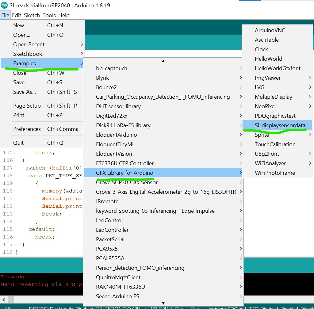
Se o carregamento for bem-sucedido, você verá os dados dos sensores exibidos na tela.
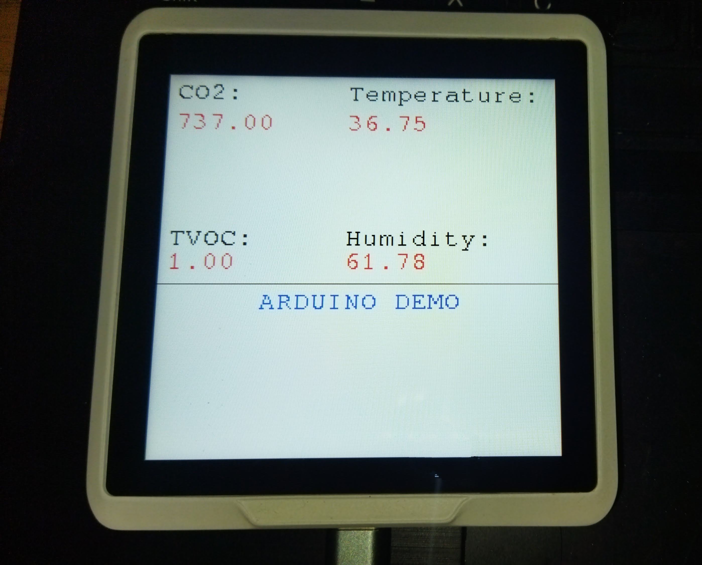
Parabéns, agora você pode desenvolver o Sensecap Indicator usando a IDE do Arduino!
O que Mais
- Ainda é a Fase UM do desenvolvimento, e o que não está configurado neste tutorial é a parte da tela sensível ao toque. Eu já testei algumas bibliotecas Arduino para o módulo FT6336, mas nenhuma teve resultado satisfatório.
- Isso se deve ao fato de o pino INT e o pino RESET do módulo FT6366 estarem conectados ao expansor I2C PCA9535 e precisarem ser configurados manualmente na biblioteca. Eu talvez volte a tentar isso no futuro.
- Aliás, para entender melhor o uso da biblioteca Arduino GFX você pode visitar a página do Arduino_GFX no GitHub
Agradecimentos Especiais
Obrigado ao usuário do GitHub u4mzu4 pelo arquivo de configuração SWSPI que oferece suporte ao Sensecap Indicator.
Obrigado a LongDirtyAnimAlf por ajudar a atualizar a biblioteca Arduino para o SenseCAP Indicator, incluindo o suporte à tela sensível ao toque.
✨ Projeto de Contribuidor
- Este projeto é apoiado pelo Projeto de Contribuidores da Seeed Studio.
- Agradecimentos aos esforços de LongDirtyAnimAlf, Hendra e u4mzu4; seu trabalho será exibido.
Suporte Técnico & Discussão de Produtos
Obrigado por escolher nossos produtos! Estamos aqui para oferecer diferentes formas de suporte para garantir que sua experiência com nossos produtos seja o mais tranquila possível. Oferecemos diversos canais de comunicação para atender a diferentes preferências e necessidades.