Multiplexação de pinos no Seeed Studio XIAO nRF52840 (Sense)
O Seeed Studio XIAO nRF52840 (Sense) possui interfaces ricas. Existem 11 E/S digitais que podem ser usadas como pinos PWM e 6 entradas analógicas que podem ser usadas como pinos ADC. Ele suporta as três interfaces de comunicação serial mais comuns, como UART, I2C e SPI. Este wiki será útil para aprender sobre essas interfaces e implementá-las em seus próximos projetos!
As funções básicas aqui funcionam bem para ambas as bibliotecas Arduino do Seeed Studio XIAO nRF52840.
Visão geral de hardware
- XIAO nRF52840
- XIAO nRF52840 Plus
- XIAO nRF52840 Sense
- XIAO nRF52840 Sense Plus
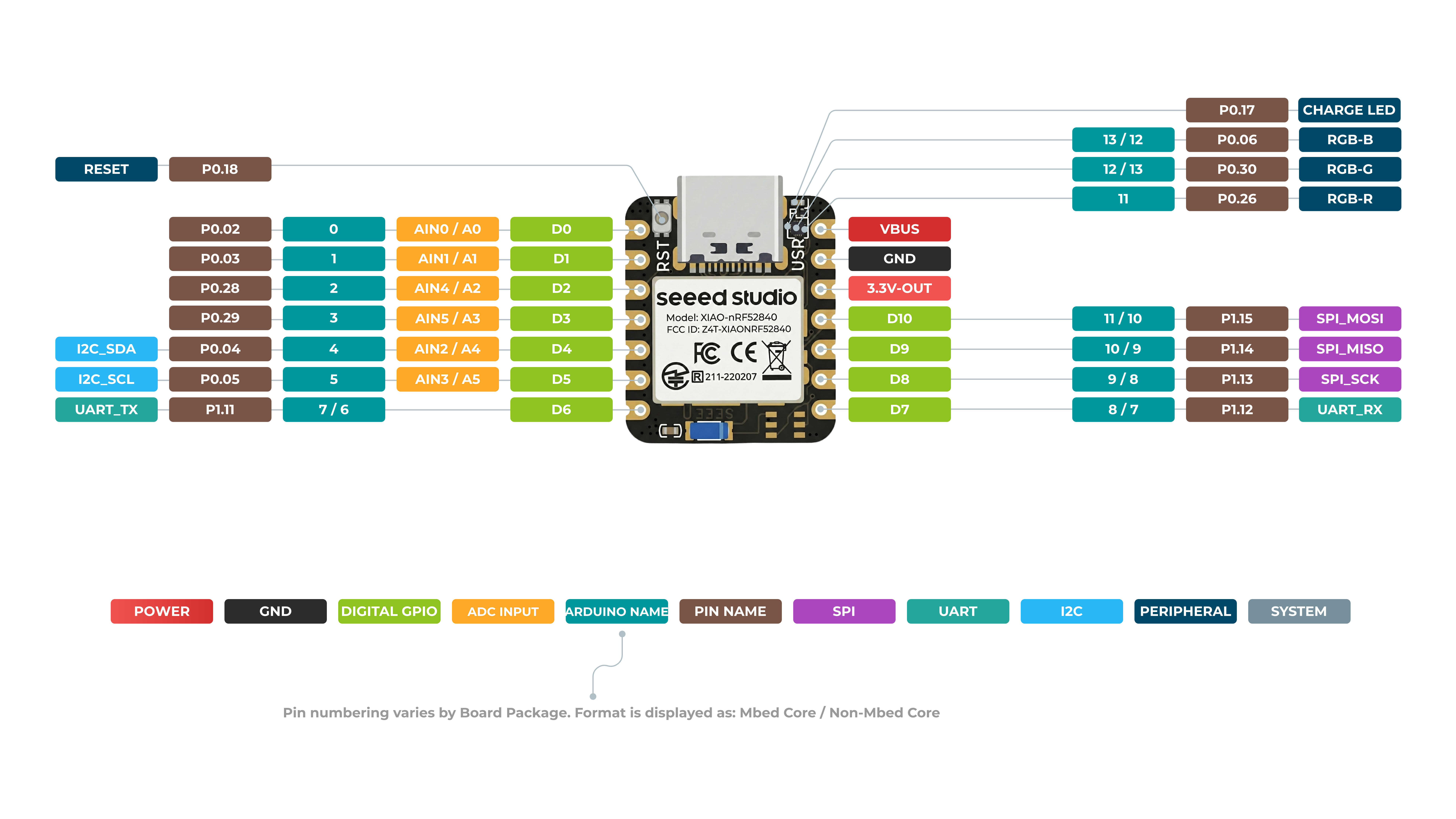
Frente do XIAO nRF52840
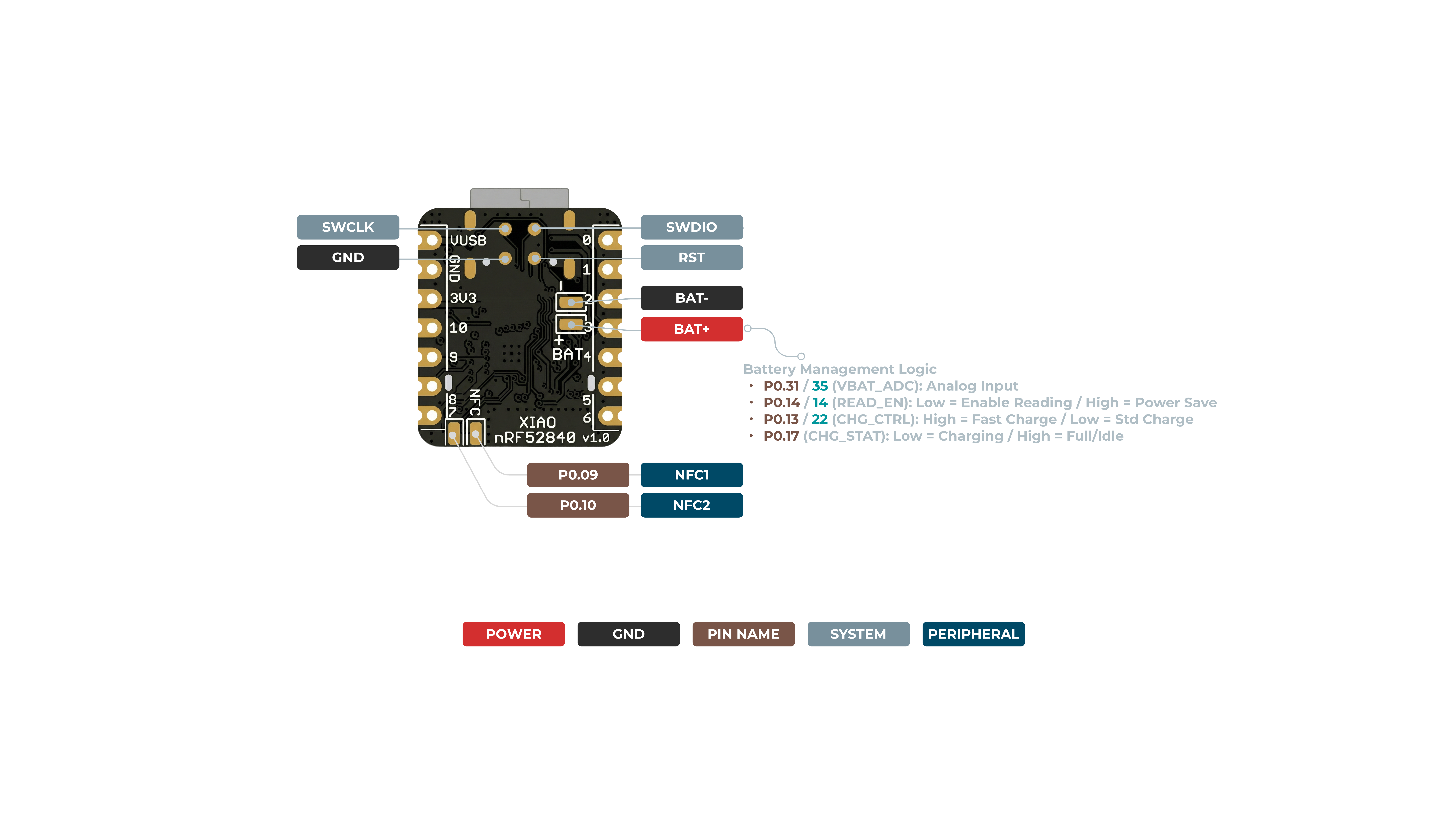
Verso do XIAO nRF52840
Mapa de pinos
| Pino XIAO | Função | Pino do chip | Descrição | Nome Arduino |
|---|---|---|---|---|
| 5V | VBUS | Entrada/Saída de energia | ||
| GND | ||||
| 3V3 | 3V3_OUT | Saída de energia | ||
| D0 | Analógico | P0.02 | GPIO, AIN0 | 0 |
| D1 | Analógico | P0.03 | GPIO, AIN1 | 1 |
| D2 | Analógico | P0.28 | GPIO, AIN4 | 2 |
| D3 | Analógico | P0.29 | GPIO, AIN5 | 3 |
| D4 | Analógico, SDA | P0.04 | GPIO, dados I2C, AIN2 | 4 |
| D5 | Analógico, SCL | P0.05 | GPIO, clock I2C, AIN3 | 5 |
| D6 | TX | P1.11 | GPIO, transmissão UART | 7/6 |
| D7 | RX | P1.12 | GPIO, recepção UART | 8/7 |
| D8 | SPI_SCK | P1.13 | GPIO, clock SPI | 9/8 |
| D9 | SPI_MISO | P1.14 | GPIO, dados SPI | 10/9 |
| D10 | SPI_MOSI | P1.15 | GPIO, dados SPI | 11/10 |
| NFC1 | P0.09 | NFC | ||
| NFC2 | P0.10 | NFC | ||
| Reset | P0.18 | RESET | ||
| ADC_BAT | READ_BAT_ENABLE | P0.14 | Controle de habilitação para leitura da tensão da bateria | |
| RF Switch Port Select | P2.05 | Alternar antena onboard | ||
| RF Switch Power | P2.03 | Alimentação | ||
| CHARGE_LED | P0.17 | CHG-LED_Red | ||
| USER_LED_R | P0.26 | Pino de LED RGB vermelho controlado pelo usuário | 11 | |
| USER_LED_B | P0.06 | Pino de LED RGB azul controlado pelo usuário | 13/12 | |
| USER_LED_G | P0.30 | Pino de LED RGB verde controlado pelo usuário | 12/13 |
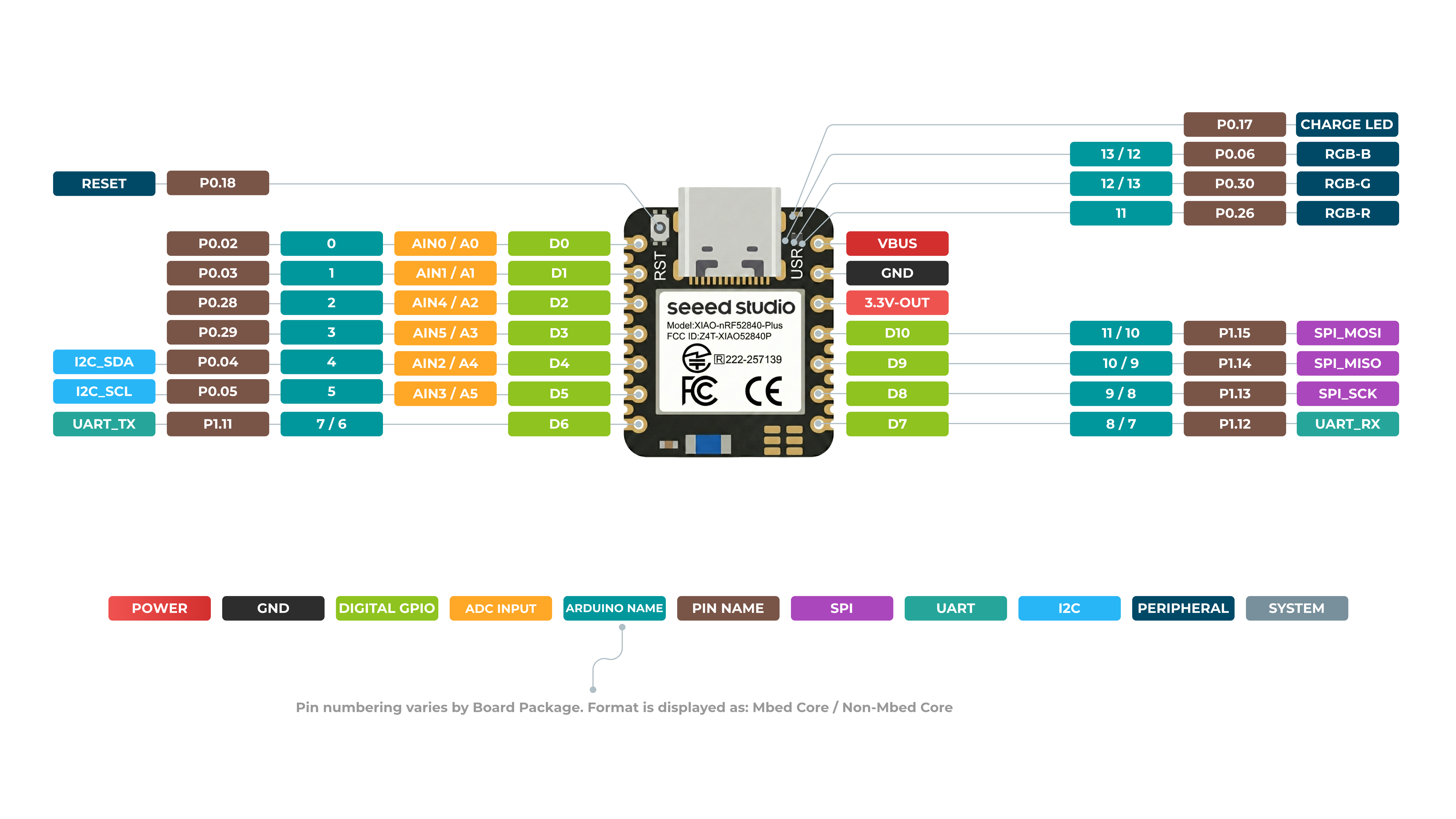
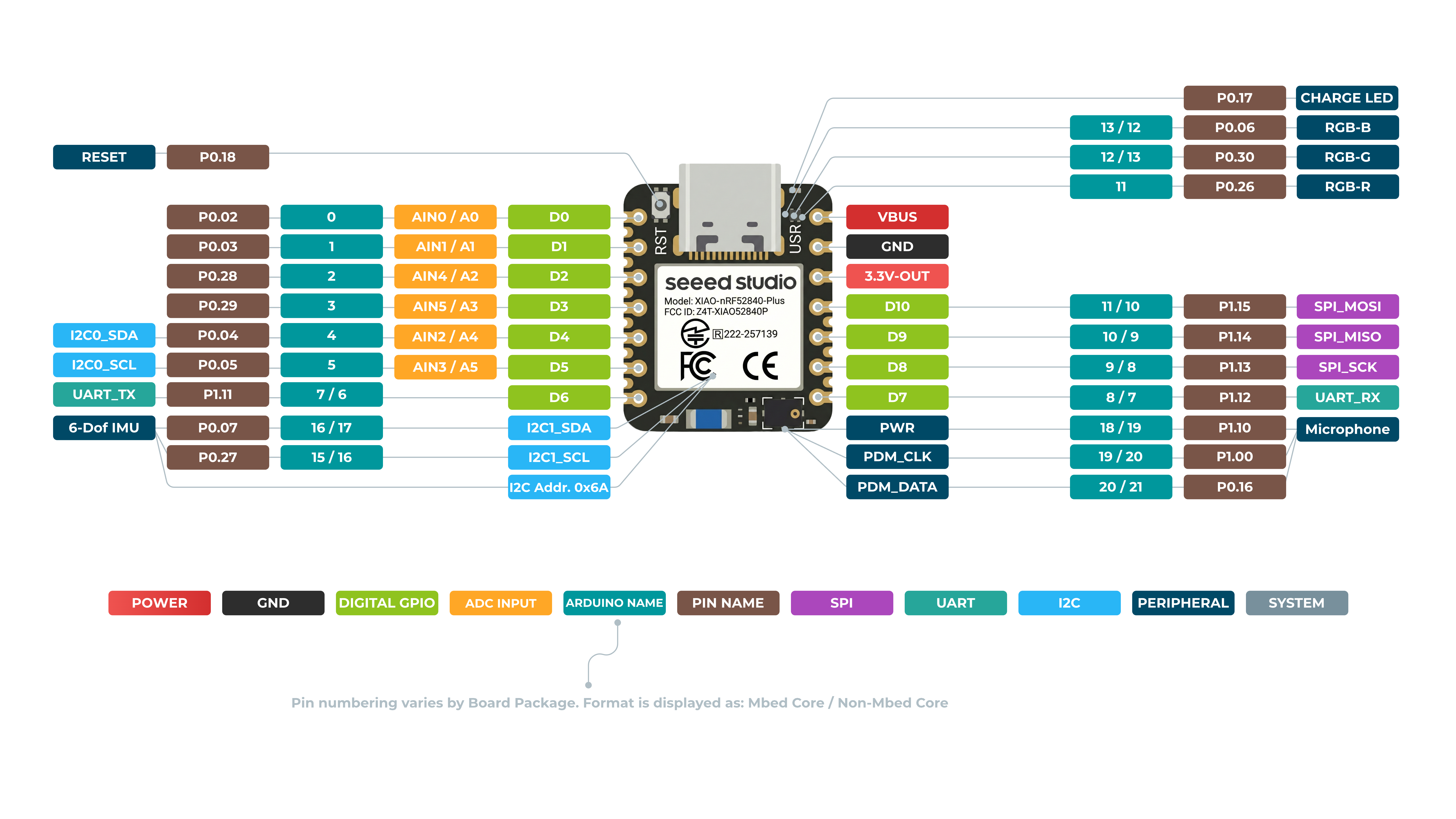
Frente do XIAO nRF52840 Plus
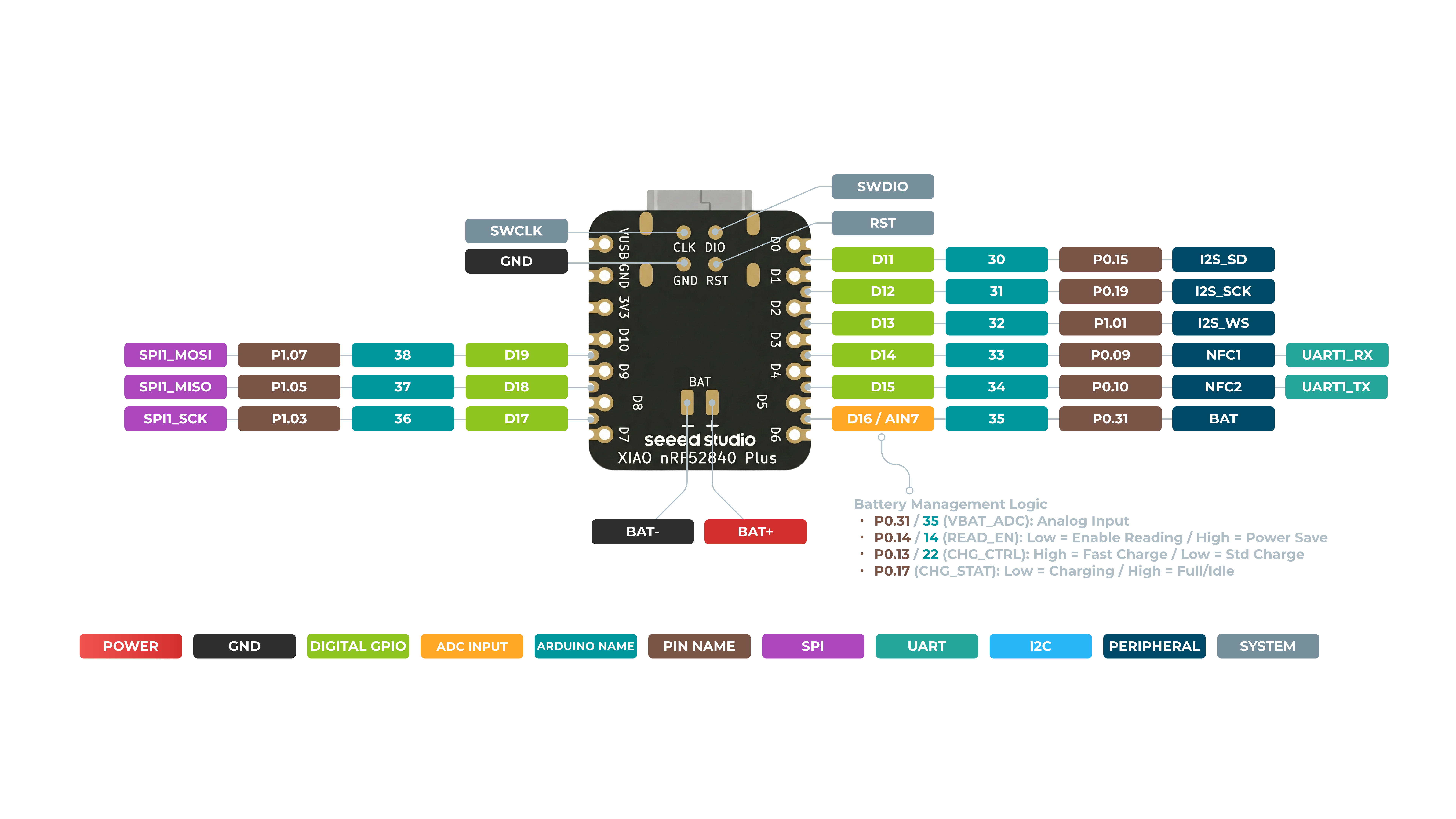
Verso do XIAO nRF52840 Plus

Mapa de pinos
| Pino XIAO | Função | Pino do chip | Funções alternativas | Descrição | Nome Arduino |
|---|---|---|---|---|---|
| 5V | VBUS | Entrada/Saída de energia | |||
| GND | |||||
| 3V3 | 3V3_OUT | Saída de energia | |||
| D0 | Analógico | P0.02 | GPIO, ADC | 0 | |
| D1 | Analógico | P0.03 | GPIO, ADC | 1 | |
| D2 | Analógico | P0.28 | GPIO, ADC | 2 | |
| D3 | Analógico | P0.29 | GPIO, ADC | 3 | |
| D4 | Analógico, SDA | P0.04 | GPIO, dados I2C, ADC | 4 | |
| D5 | Analógico, SCL | P0.05 | GPIO, clock I2C, ADC | 5 | |
| D6 | TX | P1.11 | GPIO, transmissão UART | 7/6 | |
| D7 | RX | P1.12 | GPIO, recepção UART | 8/7 | |
| D8 | SPI_SCK | P1.13 | GPIO, clock SPI | 9/8 | |
| D9 | SPI_MISO | P1.14 | GPIO, dados SPI | 10/9 | |
| D10 | SPI_MOSI | P1.15 | GPIO, dados SPI | 11/10 | |
| D11 | I2S_SD | P0.15 | GPIO, I2S, ADC | ||
| D12 | I2S_SCK | P0.19 | GPIO, I2S, ADC | ||
| D13 | I2S_WS | P1.01 | GPIO, I2S, ADC | ||
| D14 | RX1 | P0.09 | NFC1 | GPIO, recepção UART, ADC | |
| D15 | TX1 | P0.10 | NFC2 | GPIO, transmissão UART, ADC | |
| D16 | AIN7_BAT | P0.31 | Pino de leitura ADC da tensão da bateria | ||
| D17 | SCK1 | P1.03 | GPIO, SPI | ||
| D18 | MISO1 | P1.05 | GPIO, SPI | ||
| D19 | MOSI1 | P1.07 | GPIO, SPI | ||
| ADC_BAT | READ_BAT_ENABLE | P0.14 | Controle de habilitação para leitura da tensão da bateria | ||
| Reset | P0.18 | RESET | |||
| RF Switch Port Select | P2.05 | Alternar antena onboard | |||
| RF Switch Power | P2.03 | Alimentação | |||
| CHARGE_LED | P0.17 | CHG-LED_Red | |||
| USER_LED_R | P0.26 | Pino de LED RGB vermelho controlado pelo usuário | 11 | ||
| USER_LED_B | P0.06 | Pino de LED RGB azul controlado pelo usuário | 13/12 | ||
| USER_LED_G | P0.30 | Pino de LED RGB verde controlado pelo usuário | 12/13 |
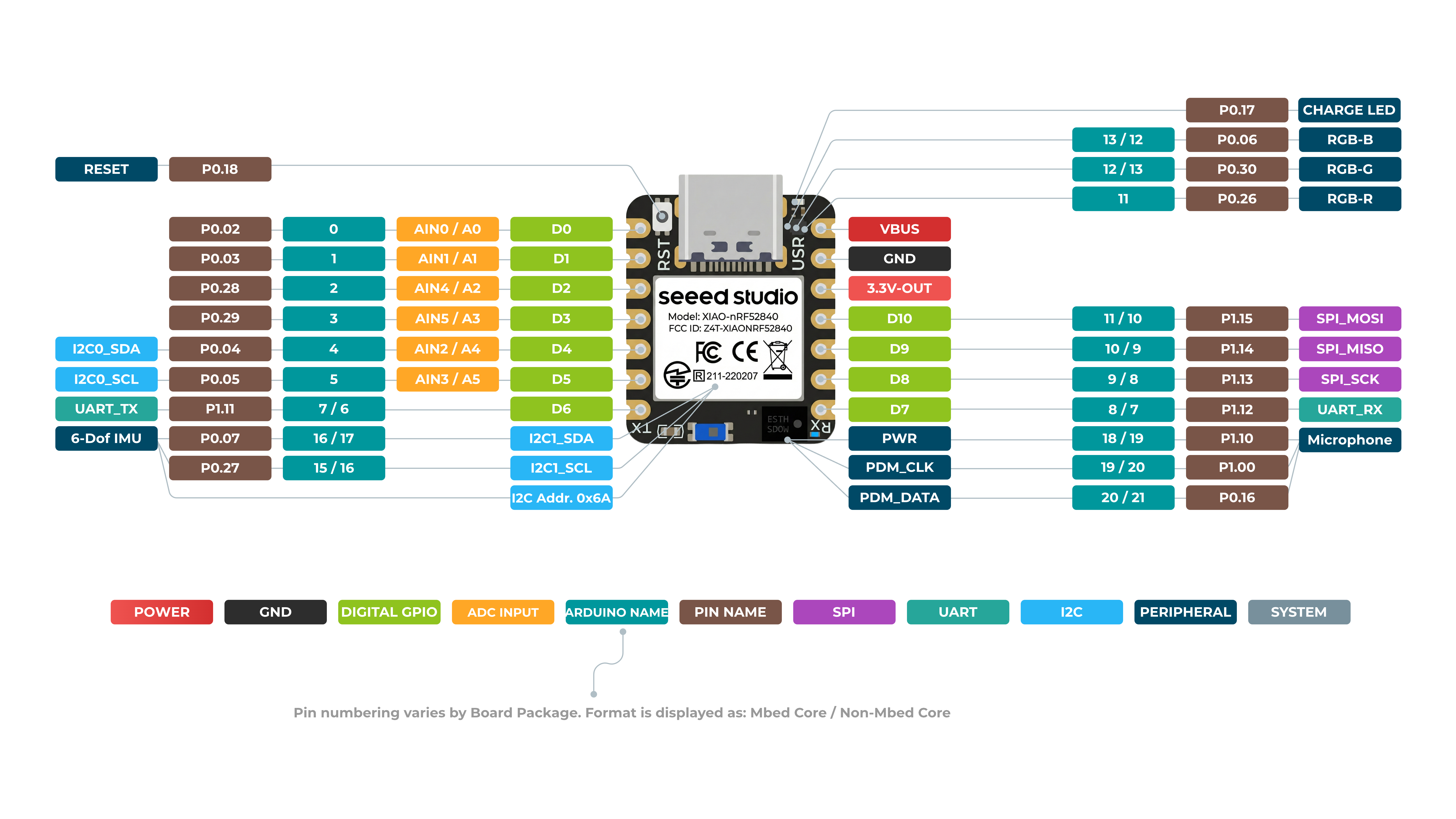
Frente do XIAO nRF52840 Sense
Verso do XIAO nRF52840 Sense

Mapa de pinos
| Pino XIAO | Função | Pino do chip | Descrição | Nome Arduino |
|---|---|---|---|---|
| 5V | VBUS | Entrada/Saída de alimentação | ||
| GND | ||||
| 3V3 | 3V3_OUT | Saída de alimentação | ||
| D0 | Analógico | P0.02 | GPIO, AIN0 | 0 |
| D1 | Analógico | P0.03 | GPIO, AIN1 | 1 |
| D2 | Analógico | P0.28 | GPIO, AIN4 | 2 |
| D3 | Analógico | P0.29 | GPIO, AIN5 | 3 |
| D4 | Analógico, SDA | P0.04 | GPIO, dados I2C, AIN2 | 4 |
| D5 | Analógico, SCL | P0.05 | GPIO, clock I2C, AIN3 | 5 |
| D6 | TX | P1.11 | GPIO, transmissão UART | 7/6 |
| D7 | RX | P1.12 | GPIO, recepção UART | 8/7 |
| D8 | SPI_SCK | P1.13 | GPIO, clock SPI | 9/8 |
| D9 | SPI_MISO | P1.14 | GPIO, dados SPI | 10/9 |
| D10 | SPI_MOSI | P1.15 | GPIO, dados SPI | 11/10 |
| NFC1 | P0.09 | NFC | ||
| NFC2 | P0.10 | NFC | ||
| Reset | P0.18 | RESET | ||
| ADC_BAT | READ_BAT_ENABLE | P0.14 | Controle de habilitação para leitura da tensão da bateria | |
| 6 DOF IMU_PWR | P1.08 | Interruptor de alimentação do módulo 6D | ||
| 6 DOF IMU__INT1 | P0.11 | Pino de sinal de interrupção do módulo 6D | ||
| PDM Microphone_DATA | P0.16 | Pino de entrada de dados de áudio PDM | ||
| PDM Microphone_CLK | P1.00 | Pino de saída de clock de áudio PDM | ||
| RF Switch Port Select | P2.05 | Alternar antena onboard | ||
| RF Switch Power | P2.03 | Alimentação | ||
| CHARGE_LED | P0.17 | CHG-LED_Red | ||
| USER_LED_R | P0.26 | Pino de LED RGB vermelho controlado pelo usuário | 11 | |
| USER_LED_B | P0.06 | Pino de LED RGB azul controlado pelo usuário | 13/12 | |
| USER_LED_G | P0.30 | Pino de LED RGB verde controlado pelo usuário | 12/13 |
XIAO nRF52840 Sense Plus Frente
XIAO nRF52840 Sense Plus Verso
Mapa de pinos
| Pino XIAO | Função | Pino do chip | Funções alternativas | Descrição | Nome Arduino |
|---|---|---|---|---|---|
| 5V | VBUS | Entrada/Saída de alimentação | |||
| GND | |||||
| 3V3 | 3V3_OUT | Saída de alimentação | |||
| D0 | Analógico | P0.02 | GPIO, ADC | 0 | |
| D1 | Analógico | P0.03 | GPIO, ADC | 1 | |
| D2 | Analógico | P0.28 | GPIO, ADC | 2 | |
| D3 | Analógico | P0.29 | GPIO, ADC | 3 | |
| D4 | Analógico, SDA | P0.04 | GPIO, dados I2C, ADC | 4 | |
| D5 | Analógico, SCL | P0.05 | GPIO, clock I2C, ADC | 5 | |
| D6 | TX | P1.11 | GPIO, transmissão UART | 7/6 | |
| D7 | RX | P1.12 | GPIO, recepção UART | 8/7 | |
| D8 | SPI_SCK | P1.13 | GPIO, clock SPI | 9/8 | |
| D9 | SPI_MISO | P1.14 | GPIO, dados SPI | 10/9 | |
| D10 | SPI_MOSI | P1.15 | GPIO, dados SPI | 11/10 | |
| D11 | I2S_SD | P0.15 | GPIO, I2S, ADC | ||
| D12 | I2S_SCK | P0.19 | GPIO, I2S, ADC | ||
| D13 | I2S_WS | P1.01 | GPIO, I2S, ADC | ||
| D14 | RX1 | P0.09 | NFC1 | GPIO, recepção UART, ADC | |
| D15 | TX1 | P0.10 | NFC2 | GPIO, transmissão UART, ADC | |
| D16 | AIN7_BAT | P0.31 | Pino de leitura ADC da tensão da bateria | ||
| D17 | SCK1 | P1.03 | GPIO, SPI | ||
| D18 | MISO1 | P1.05 | GPIO, SPI | ||
| D19 | MOSI1 | P1.07 | GPIO, SPI | ||
| ADC_BAT | READ_BAT_ENABLE | P0.14 | Controle de habilitação para leitura da tensão da bateria | ||
| 6 DOF IMU_PWR | P1.08 | Interruptor de alimentação do módulo 6D | |||
| 6 DOF IMU__INT1 | P0.11 | Pino de sinal de interrupção do módulo 6D | |||
| PDM Microphone_DATA | P0.16 | Pino de entrada de dados de áudio PDM | |||
| PDM Microphone_CLK | P1.00 | Pino de saída de clock de áudio PDM | |||
| Reset | P0.18 | RESET | |||
| RF Switch Port Select | P2.05 | Alternar antena onboard | |||
| RF Switch Power | P2.03 | Alimentação | |||
| CHARGE_LED | P0.17 | CHG-LED_Red | |||
| USER_LED_R | P0.26 | Pino de LED RGB vermelho controlado pelo usuário | 11 | ||
| USER_LED_B | P0.06 | Pino de LED RGB azul controlado pelo usuário | 13/12 | ||
| USER_LED_G | P0.30 | Pino de LED RGB verde controlado pelo usuário | 12/13 |
Digital
Conecte um botão de pressão ao pino D6 e um LED ao pino D10. Em seguida, envie o seguinte código para controlar o LIGAR/DESLIGAR do LED usando o botão de pressão.
const int buttonPin = 6;     // pushbutton connected to digital pin 6
const int ledPin =  10;      // LED connected to digital pin 10

int buttonState = 0;         // variable for reading the pushbutton status

void setup() {
  // initialize the LED pin as an output:
  pinMode(ledPin, OUTPUT);
  // initialize the pushbutton pin as an input:
  pinMode(buttonPin, INPUT);
}

void loop() {
  // read the state of the pushbutton value:
  buttonState = digitalRead(buttonPin);

  // check if the pushbutton is pressed. If it is, the buttonState is HIGH:
  if (buttonState == HIGH) {
    // turn LED off:
    digitalWrite(ledPin, HIGH);
  } else {
    // turn LED on:
    digitalWrite(ledPin, LOW);
  }
}
Digital como PWM
Conecte um LED ao pino D10. Em seguida, envie o código a seguir para ver o LED desvanecendo gradualmente.
int ledPin = 10;    // LED connected to digital pin 10

void setup() {

}

void loop() {
  // fade in from min to max in increments of 5 points:
  for (int fadeValue = 0 ; fadeValue <= 255; fadeValue += 5) {
    // sets the value (range from 0 to 255):
    analogWrite(ledPin, fadeValue);
    // wait for 30 milliseconds to see the dimming effect
    delay(30);
  }

  // fade out from max to min in increments of 5 points:
  for (int fadeValue = 255 ; fadeValue >= 0; fadeValue -= 5) {
    // sets the value (range from 0 to 255):
    analogWrite(ledPin, fadeValue);
    // wait for 30 milliseconds to see the dimming effect
    delay(30);
  }
}
Analógico
Conecte um potenciômetro ao pino A5 e um LED ao pino D10. Em seguida, envie o código a seguir para controlar o intervalo de piscar do LED girando o botão do potenciômetro.
const int sensorPin = 5;
const int ledPin =  10;
void setup() {
  // declare the ledPin as an OUTPUT:
  pinMode(sensorPin, INPUT);
  pinMode(ledPin, OUTPUT);
}

void loop() {
  // read the value from the sensor:
  int sensorValue = analogRead(sensorPin);
  // turn the ledPin on
  digitalWrite(ledPin, HIGH);
  // stop the program for <sensorValue> milliseconds:
  delay(sensorValue);
  // turn the ledPin off:
  digitalWrite(ledPin, LOW);
  // stop the program for for <sensorValue> milliseconds:
  delay(sensorValue);
}
Serial
Use Serial1 para usar o UART via GPIO em vez de USB. Você também pode usar ambos simultaneamente. Use o pino D6 como pino TX do UART e o pino D7 como pino RX do UART para enviar a mensagem "Hello World!".
void setup() {
    Serial1.begin(115200);
    while (!Serial1);
}

void loop() {
    Serial1.println("Hello World!");
    delay(1000);
}
I2C
- Passo 1. Conecte um Grove - OLED Display 1.12 (SH1107) V3.0 ao Seeed Studio XIAO nRF52840 (Sense) seguindo a conexão de hardware a seguir.
| Grove - OLED Display 1.12 (SH1107) | Seeed Studio XIAO nRF52840 (Sense) |
|---|---|
| GND | GND |
| VCC | 5V |
| SDA | SDA |
| SCL | SCL |

-
Passo 2. Abra o Arduino IDE, navegue até
Sketch > Include Library > Manage Libraries... -
Passo 3. Procure por u8g2 e instale-o

- Passo 4. Envie o código a seguir para exibir strings de texto no OLED Display
#include <Arduino.h>
#include <U8g2lib.h>
#include <SPI.h>
#include <Wire.h>

U8G2_SH1107_SEEED_128X128_1_SW_I2C u8g2(U8G2_R0, /* clock=*/ 5, /* data=*/ 4, /* reset=*/ U8X8_PIN_NONE);

void setup(void) {
  u8g2.begin();
}

void loop(void) {
  u8g2.firstPage();

  do {
    u8g2.setFont(u8g2_font_luBIS08_tf);
    u8g2.drawStr(0,24,"Hello Seeed!");
  } while ( u8g2.nextPage() );
}
SPI
- Passo 1. Conecte um Grove - OLED Display 1.12 (SH1107) V3.0 ao Seeed Studio XIAO nRF52840 (Sense) seguindo a conexão de hardware a seguir.
| Grove - OLED Display 1.12 (SH1107) | Seeed Studio XIAO nRF52840 (Sense) |
|---|---|
| GND | GND |
| 5V | 5V |
| SCL | SCK |
| SI | MOSI |
| RES | D3 |
| D/C | D4 |
| CS | D5 |

- Passo 2. Este display OLED suporta comunicação tanto I2C quanto SPI, e o modo padrão é I2C. Para usar o modo SPI, você precisa consultar o Grove - OLED Display 1.12 (SH1107) V3.0 wiki para alterar a comunicação do display OLED para SPI antes de prosseguir
Nota: Certifique-se de que a biblioteca U8g2 esteja instalada a partir dos passos anteriores.
- Passo 3. Envie o código a seguir para exibir strings de texto no OLED Display
#include <Arduino.h>
#include <U8g2lib.h>
#include <SPI.h>
#include <Wire.h>

U8G2_SH1107_128X128_1_4W_HW_SPI u8g2(U8G2_R3, /* cs=*/ 5, /* dc=*/ 4, /* reset=*/ 3);

void setup(void) {
  u8g2.begin();
}

void loop(void) {
  u8g2.firstPage();

  do {
    u8g2.setFont(u8g2_font_luBIS08_tf);
    u8g2.drawStr(0,24,"Hello Seeed!");
  } while ( u8g2.nextPage() );
}