Multiplexação de pinos
O Seeed Studio XIAO ESP32C3 possui interfaces ricas. Existem 11 E/S digitais que podem ser usadas como pinos PWM e 4 entradas analógicas que podem ser usadas como pinos ADC. Ele suporta quatro interfaces de comunicação serial, como UART, I2C, SPI e I2S. Este wiki será útil para aprender sobre essas interfaces e implementá-las em seus próximos projetos!
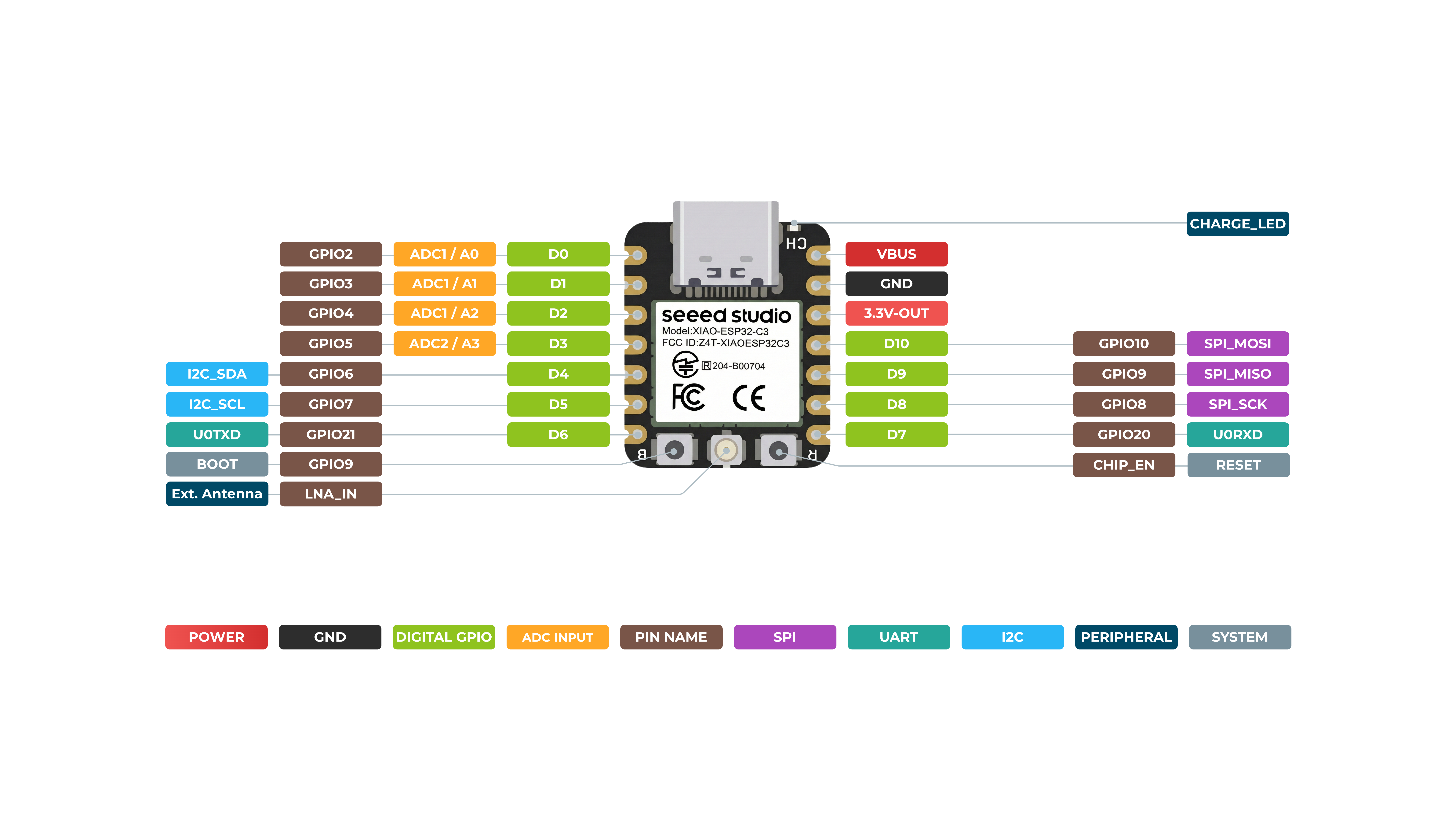
Visão geral de hardware
*A3(GP105) - Usa o ADC2, que pode se tornar inoperante devido a sinais de amostragem falsos. Para leituras analógicas confiáveis, use o ADC1(A0/A1/A2). Consulte o datasheet do ESP32-C3.
Frente
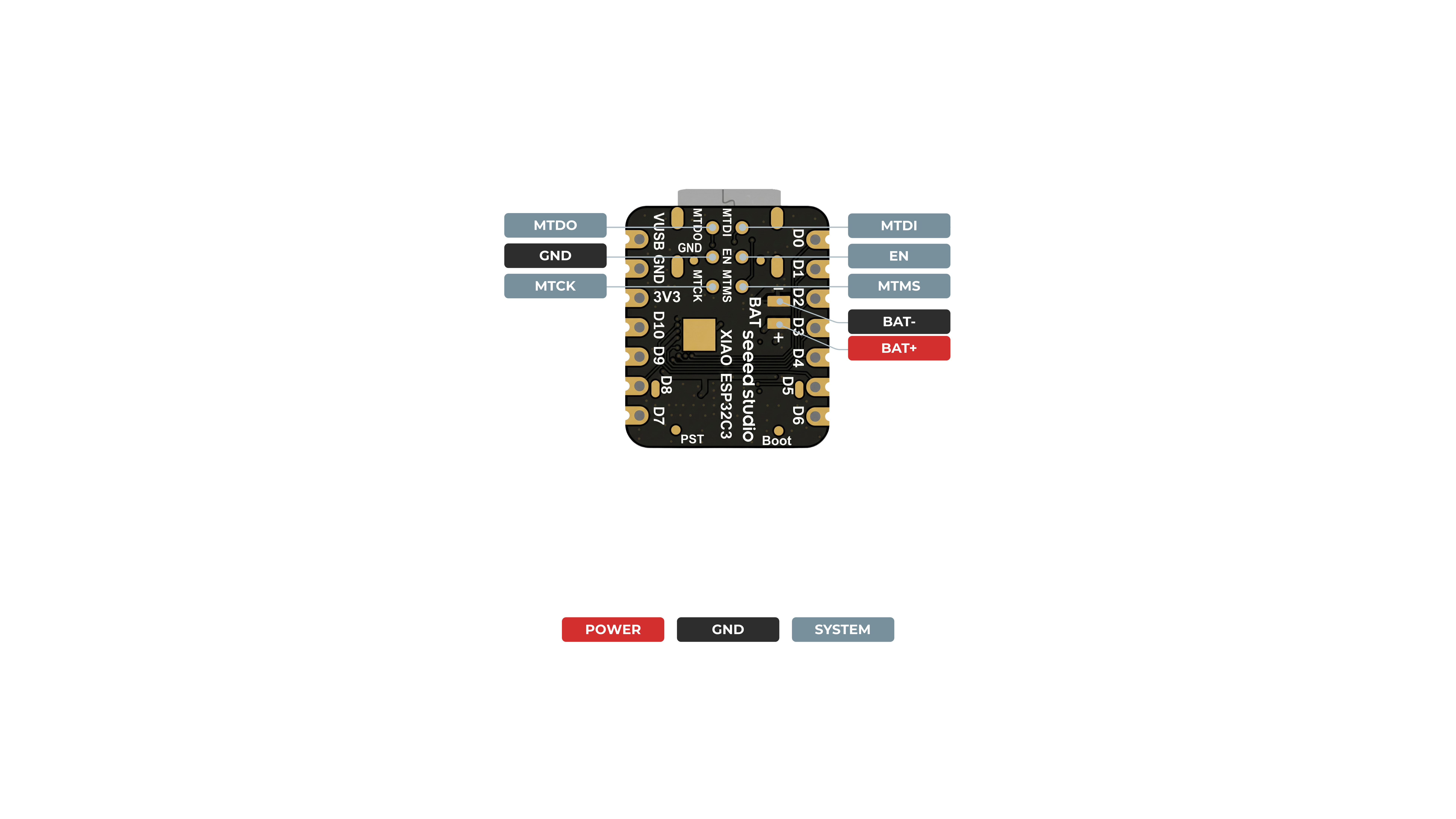
Verso
Digital
Conecte um botão ao pino D6 e um LED ao pino D10. Em seguida, envie o código a seguir para controlar o LIGAR/DESLIGAR do LED usando o botão.
const int buttonPin = D6;     // pushbutton connected to digital pin 6
const int ledPin =  D10;      // LED connected to digital pin 10

int buttonState = 0;         // variable for reading the pushbutton status

void setup() {
  // initialize the LED pin as an output:
  pinMode(ledPin, OUTPUT);
  // initialize the pushbutton pin as an input:
  pinMode(buttonPin, INPUT);
}

void loop() {
  // read the state of the pushbutton value:
  buttonState = digitalRead(buttonPin);

  // check if the pushbutton is pressed. If it is, the buttonState is HIGH:
  if (buttonState == HIGH) {
    // turn LED on:
    digitalWrite(ledPin, HIGH);
  } else {
    // turn LED off:
    digitalWrite(ledPin, LOW);
  }
}
Digital como PWM
Conecte um LED ao pino D10. Em seguida, envie o código a seguir para ver o LED desvanecendo gradualmente.
int ledPin = D10;    // LED connected to digital pin 10

void setup() {
  // declaring LED pin as output
  pinMode(ledPin, OUTPUT);
}

void loop() {
  // fade in from min to max in increments of 5 points:
  for (int fadeValue = 0 ; fadeValue <= 255; fadeValue += 5) {
    // sets the value (range from 0 to 255):
    analogWrite(ledPin, fadeValue);
    // wait for 30 milliseconds to see the dimming effect
    delay(30);
  }

  // fade out from max to min in increments of 5 points:
  for (int fadeValue = 255 ; fadeValue >= 0; fadeValue -= 5) {
    // sets the value (range from 0 to 255):
    analogWrite(ledPin, fadeValue);
    // wait for 30 milliseconds to see the dimming effect
    delay(30);
  }
}
Analógico
Conecte um potenciômetro ao pino A0 e um LED ao pino D10. Em seguida, envie o código a seguir para controlar o intervalo de piscar do LED girando o botão do potenciômetro.
A faixa de mapeamento do ADC é de 0-2500mV.
const int sensorPin = A0;
const int ledPin =  D10;

void setup() {
  pinMode(sensorPin, INPUT);  // declare the sensorPin as an INPUT
  pinMode(ledPin, OUTPUT);   // declare the ledPin as an OUTPUT
}

void loop() {
  // read the value from the sensor:
  int sensorValue = analogRead(sensorPin);
  // turn the ledPin on
  digitalWrite(ledPin, HIGH);
  // stop the program for <sensorValue> milliseconds:
  delay(sensorValue);
  // turn the ledPin off:
  digitalWrite(ledPin, LOW);
  // stop the program for for <sensorValue> milliseconds:
  delay(sensorValue);
}
Serial - UART
Método comum - escolha um dos seriais USB ou UART0 para usar
Existem 2 interfaces seriais nesta placa:
- Serial USB
- Serial UART0
Não há Serial2 para o XIAO ESP32 C3.
Além disso, se você precisar usar Serial1, deverá definir os pinos; caso contrário, ele pode não receber dados. Para a série XIAO ESP32, use Serial1 da seguinte forma:
Serial1.begin(115200, SERIAL_8N1, D7, D6); // RX, TX
Por padrão, o serial USB é habilitado, o que significa que você pode conectar a placa a um PC via USB Type-C e abrir o monitor serial na IDE do Arduino para visualizar os dados enviados via serial.
No entanto, se você quiser usar o UART0 como serial, será necessário conectar o pino D6 como pino TX e o pino D7 como pino RX com um adaptador USB-Serial.
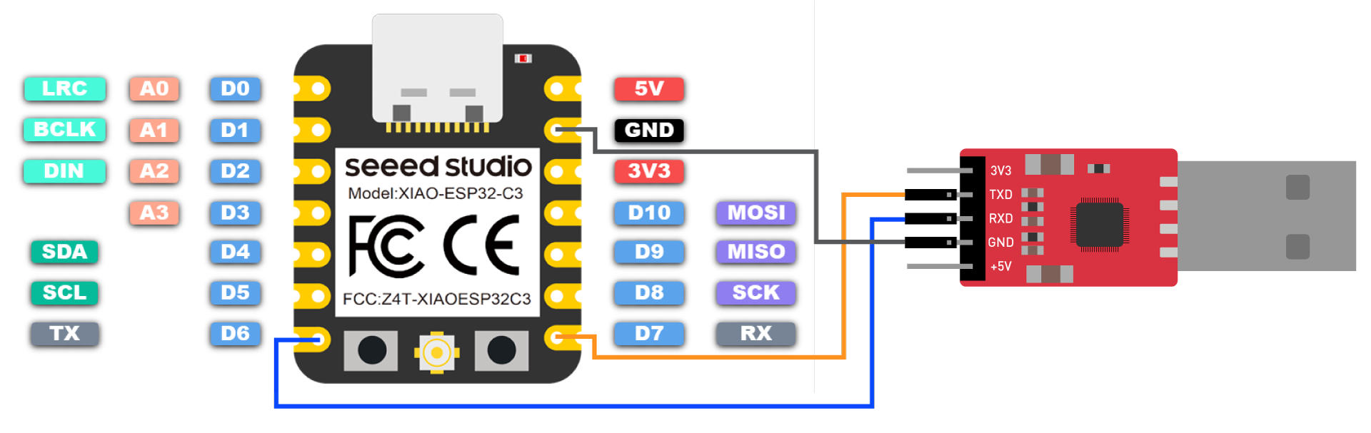
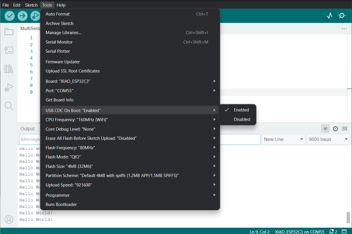
Além disso, você precisa definir USB CDC On Boot como Disabled na IDE do Arduino.
NOTA: Alterar a foto quando a placa aparecer no Arduino Board Manager
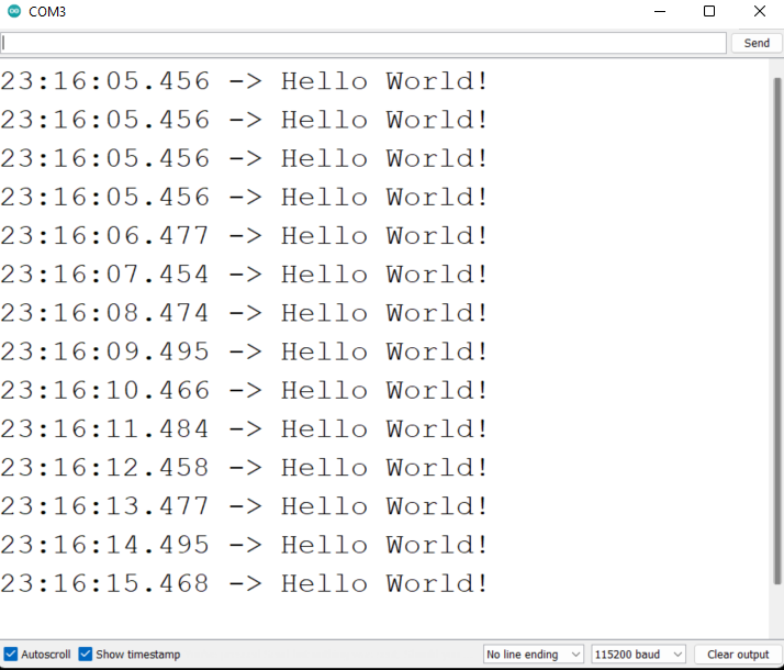
Envie o seguinte código para a IDE do Arduino para enviar a string "Hello World!" via serial
void setup() {
    Serial.begin(115200);
    while (!Serial);
}

void loop() {
    Serial.println("Hello World!");
    delay(1000);
}
A saída será a seguinte no Monitor Serial do Arduino
Forma especial - usar serial USB e UART0/UART1 ao mesmo tempo
Muitas vezes, precisamos usar sensores UART para conectar à porta serial de hardware do XIAO ESP32C3 para obter dados e, ao mesmo tempo, talvez seja necessário usar o serial USB para exibir os dados no monitor serial. Isso pode ser alcançado por alguns métodos especiais.
- Programa de exemplo:
// Need this for the lower level access to set them up.
#include <HardwareSerial.h>

//Define two Serial devices mapped to the two internal UARTs
HardwareSerial MySerial0(0);
HardwareSerial MySerial1(1);

void setup()
{
    // For the USB, just use Serial as normal:
    Serial.begin(115200);

    // Configure MySerial0 on pins TX=D6 and RX=D7 (-1, -1 means use the default)
    MySerial0.begin(9600, SERIAL_8N1, -1, -1);
    MySerial0.print("MySerial0");

    // And configure MySerial1 on pins RX=D9, TX=D10
    MySerial1.begin(115200, SERIAL_8N1, 9, 10);
    MySerial1.print("MySerial1");
}

void loop()
{

}
Como você pode ver, o XIAO ESP32C3 na verdade possui três UARTs disponíveis.
A seguir, tomaremos como exemplo o Sensor mmWave de 60GHz - Módulo de Respiração em Repouso Humano e Batimento Cardíaco, que está disponível para venda, e explicaremos como usar as portas seriais de hardware D6 e D7 e a porta serial USB.
Por favor, prepare o seguinte.
| XIAO ESP32C3 | Sensor mmWave de 60GHz - Módulo de Respiração em Repouso Humano e Batimento Cardíaco |
|---|---|
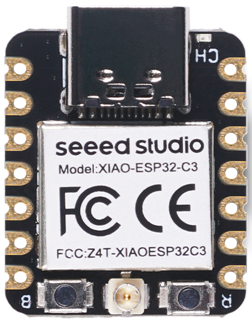 | 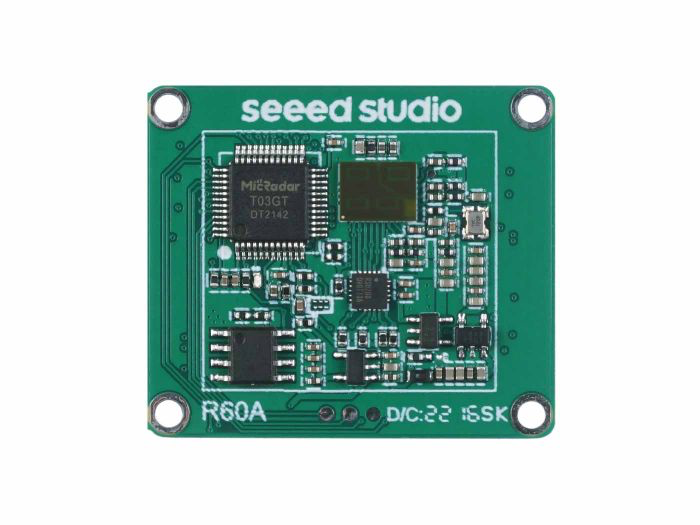 |
| Adquira agora | Adquira agora |
Baixe a biblioteca do sensor para o seu computador. E adicione-a à IDE do Arduino.
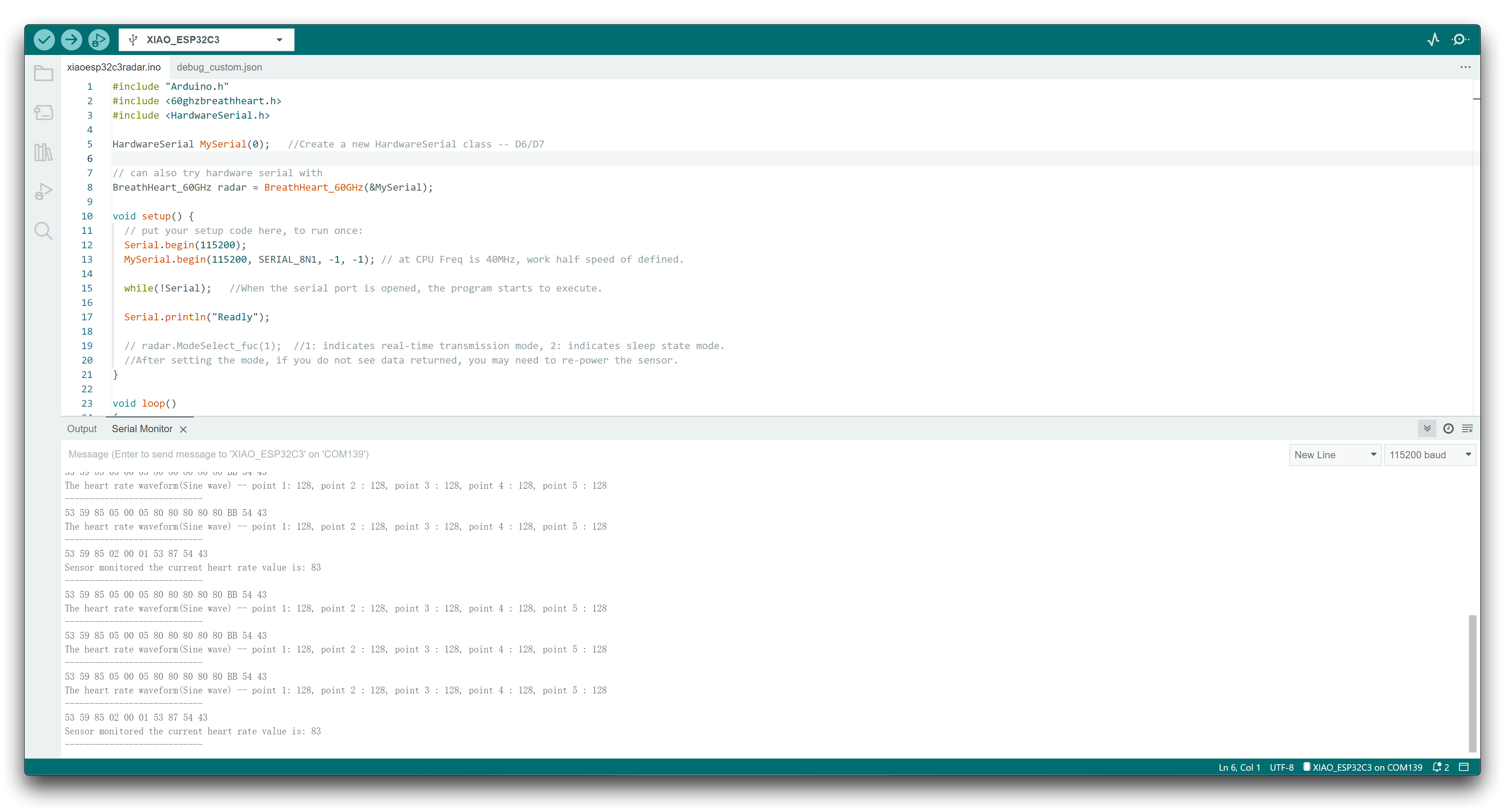
Aqui, queremos analisar as informações de dados de batimentos cardíacos e respiração, então você pode reescrever seu programa assim.
#include "Arduino.h"
#include <60ghzbreathheart.h>
#include <HardwareSerial.h>

HardwareSerial MySerial(0);   //Create a new HardwareSerial class -- D6/D7

// can also try hardware serial with
BreathHeart_60GHz radar = BreathHeart_60GHz(&MySerial);

void setup() {
  // put your setup code here, to run once:
  Serial.begin(115200);
  MySerial.begin(115200, SERIAL_8N1, -1, -1); // at CPU Freq is 40MHz, work half speed of defined.

  while(!Serial);   //When the serial port is opened, the program starts to execute.

  Serial.println("Readly");

  // radar.ModeSelect_fuc(1);  //1: indicates real-time transmission mode, 2: indicates sleep state mode.
  //After setting the mode, if you do not see data returned, you may need to re-power the sensor.
}

void loop()
{
  // put your main code here, to run repeatedly:
  radar.Breath_Heart();           //Breath and heartbeat information output
  if(radar.sensor_report != 0x00){
    switch(radar.sensor_report){
      case HEARTRATEVAL:
        Serial.print("Sensor monitored the current heart rate value is: ");
        Serial.println(radar.heart_rate, DEC);
        Serial.println("----------------------------");
        break;
      case HEARTRATEWAVE:  //Valid only when real-time data transfer mode is on
        Serial.print("The heart rate waveform(Sine wave) -- point 1: ");
        Serial.print(radar.heart_point_1);
        Serial.print(", point 2 : ");
        Serial.print(radar.heart_point_2);
        Serial.print(", point 3 : ");
        Serial.print(radar.heart_point_3);
        Serial.print(", point 4 : ");
        Serial.print(radar.heart_point_4);
        Serial.print(", point 5 : ");
        Serial.println(radar.heart_point_5);
        Serial.println("----------------------------");
        break;
      case BREATHNOR:
        Serial.println("Sensor detects current breath rate is normal.");
        Serial.println("----------------------------");
        break;
      case BREATHRAPID:
        Serial.println("Sensor detects current breath rate is too fast.");
        Serial.println("----------------------------");
        break;
      case BREATHSLOW:
        Serial.println("Sensor detects current breath rate is too slow.");
        Serial.println("----------------------------");
        break;
      case BREATHNONE:
        Serial.println("There is no breathing information yet, please wait...");
        Serial.println("----------------------------");
        break;
      case BREATHVAL:
        Serial.print("Sensor monitored the current breath rate value is: ");
        Serial.println(radar.breath_rate, DEC);
        Serial.println("----------------------------");
        break;
      case BREATHWAVE:  //Valid only when real-time data transfer mode is on
        Serial.print("The breath rate waveform(Sine wave) -- point 1: ");
        Serial.print(radar.breath_point_1);
        Serial.print(", point 2 : ");
        Serial.print(radar.breath_point_2);
        Serial.print(", point 3 : ");
        Serial.print(radar.breath_point_3);
        Serial.print(", point 4 : ");
        Serial.print(radar.breath_point_4);
        Serial.print(", point 5 : ");
        Serial.println(radar.breath_point_5);
        Serial.println("----------------------------");
        break;
    }
  }
  delay(200);                       //Add time delay to avoid program jam
}
Faça o upload do programa, depois abra o monitor serial e defina a taxa de transmissão para 115200.
Em seguida, podemos conectar o sensor ao XIAO ESP32C3 usando o seguinte método de conexão.
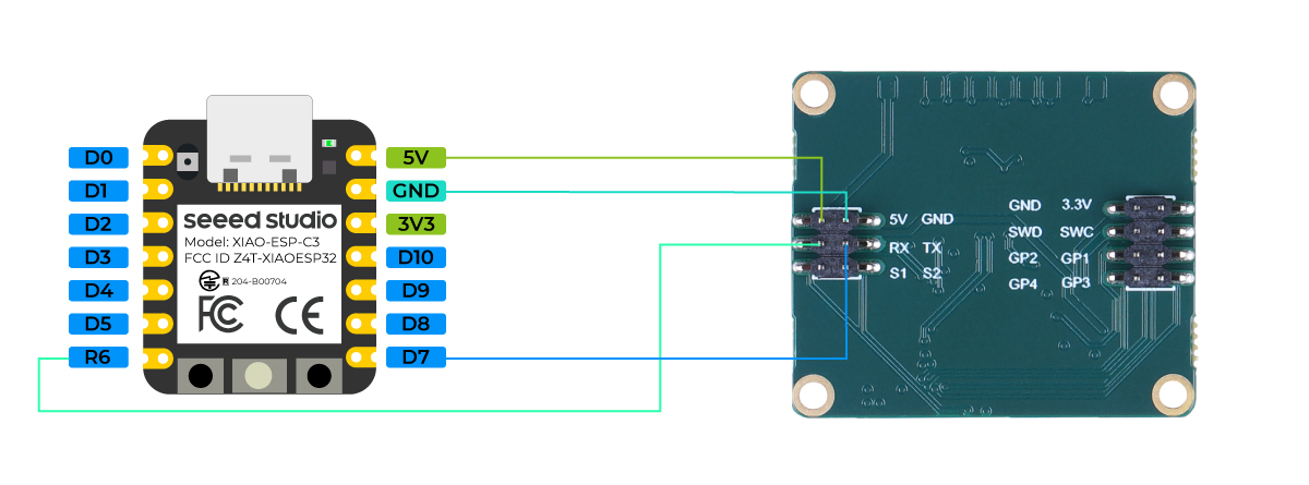
Se tudo correr bem, você verá mensagens de dados no monitor serial.
Uso do Serial1
De acordo com os diagramas de pinos do XIAO ESP32C3 acima para parâmetros específicos, podemos observar que existem pinos TX e RX. Isso é diferente da comunicação serial padrão, mas o uso também é muito semelhante, exceto que alguns parâmetros precisam ser adicionados. Então, em seguida, usaremos os pinos expostos pelo chip para comunicação serial.
Função principal que precisa ser incluída:
Serial1.begin(BAUD,SERIAL_8N1,RX_PIN,TX_PIN);-- habilita o Serial1, o protótipo da função é:<Serial.Type>.begin(unsigned long baud, uint32_t config, int8_t rxPin, int8_t txPin);baud:taxa de transmissãoconfig:bit de configuraçãorxPin:pino de recepçãotxPin:pino de envio
Vale ressaltar que, se usarmos a porta de pino digital para definir, este local deve ser #define RX_PIN D7、#define TX_PIN D6, consulte os diagramas de pinos das diferentes XIAO Series para parâmetros específicos.
Aqui está um programa de exemplo:
#define RX_PIN D7
#define TX_PIN D6
#define BAUD 115200

void setup() {
    Serial1.begin(BAUD,SERIAL_8N1,RX_PIN,TX_PIN);
}

void loop() {
  if(Serial1.available() > 0)
  {
    char incominByte = Serial1.read();
    Serial1.print("I received : ");
    Serial1.println(incominByte);
  }
  delay(1000);
}
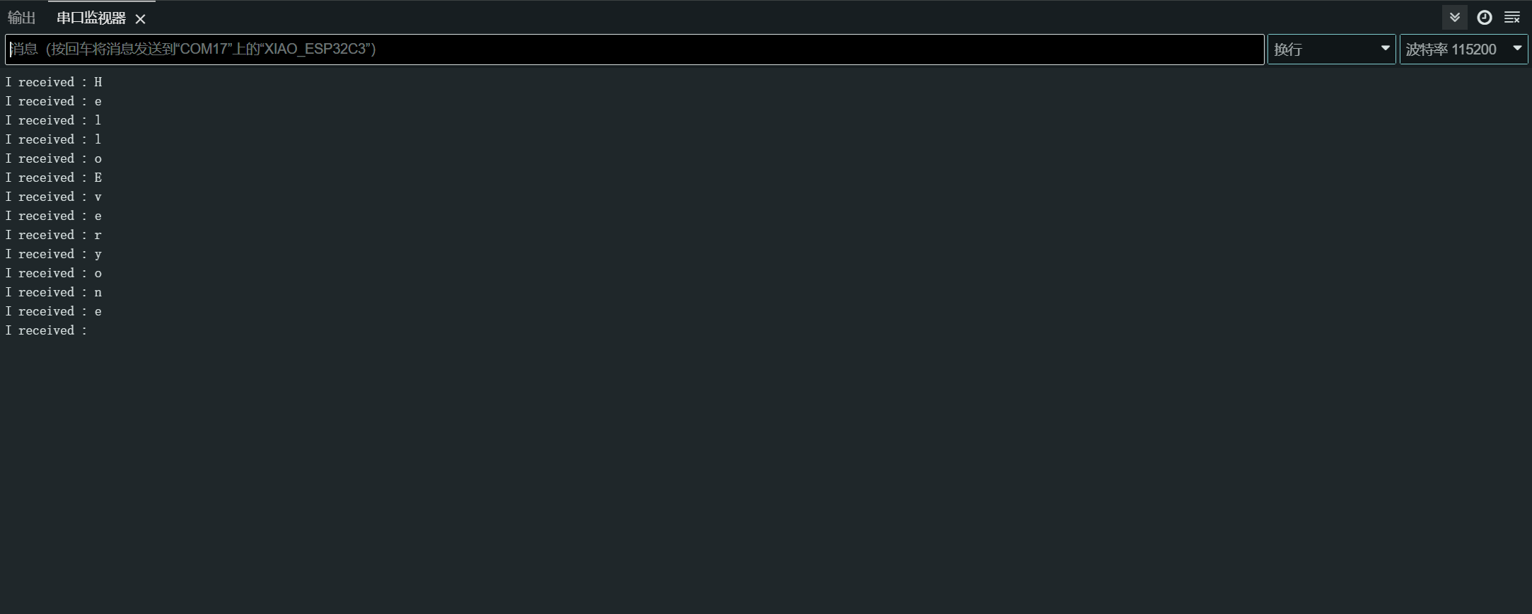
Depois de fazer o upload do programa, abra o Serial Monitor na Arduino IDE e defina a taxa de transmissão para 115200. Então, você pode enviar o conteúdo que quiser para o XIAO ESP32C3 através do Serial Monitor, e o XIAO imprimirá cada byte do conteúdo que você enviar. Aqui, o conteúdo que inseri é "Hello Everyone", meu gráfico de resultados é o seguinte
Software Serial
Para usar software serial, instale a biblioteca EspSoftwareSerial.
Atualmente recomendamos a versão 7.0.0 da biblioteca EspSoftwareSerial. Outras versões podem ter diferentes graus de problemas que impedem que a porta serial por software funcione corretamente.
#include <SoftwareSerial.h>

SoftwareSerial mySerial(D7, D6); // RX, TX

void setup() {
  Serial.begin(9600);
  mySerial.begin(9600);
}

void loop() {
  if (mySerial.available()) {
    char data = mySerial.read();
    Serial.print("Received via software serial: ");
    Serial.println(data);
  }

  if (Serial.available()) {
    char data = Serial.read();
    mySerial.print("Received via hardware serial: ");
    mySerial.println(data);
  }
}
Este exemplo configura o software serial nos pinos D7 (RX) e D6 (TX) a 9600 baud. Ele monitora tanto a serial de hardware (USB) quanto as portas seriais por software, ecoando os dados recebidos entre elas.
I2C
Conexão de hardware
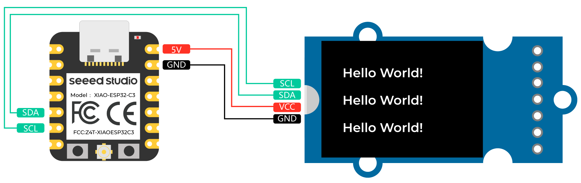
Conecte um Grove - OLED Yellow&Blue Display 0.96 (SSD1315) ao XIAO ESP32C3 seguindo a conexão de hardware a seguir.
| Grove - OLED Yellow&Blue Display 0.96 (SSD1315) | XIAO ESP32C3 |
|---|---|
| SCL | SCL |
| SDA | SDA |
| VCC | 5V |
| GND | GND |
Configuração de software
-
Passo 1. Abra a Arduino IDE, navegue até
Sketch > Include Library > Manage Libraries... -
Passo 2. Procure por u8g2 e instale

- Passo 3. Faça o upload do código a seguir para exibir strings de texto no OLED Display
//#include <Arduino.h>
#include <U8g2lib.h>

#ifdef U8X8_HAVE_HW_SPI
#include <SPI.h>
#endif
#ifdef U8X8_HAVE_HW_I2C
#include <Wire.h>
#endif

U8G2_SSD1306_128X64_NONAME_F_SW_I2C u8g2(U8G2_R0, /* clock=*/ SCL, /* data=*/ SDA, /* reset=*/ U8X8_PIN_NONE);    //Low spped I2C

void setup(void) {
  u8g2.begin();
//  u8x8.setFlipMode(1);   // set number from 1 to 3, the screen word will rotary 180
}

void loop(void) {
  u8g2.clearBuffer();                   // clear the internal memory
  u8g2.setFont(u8g2_font_ncenB08_tr);   // choose a suitable font
  u8g2.drawStr(0,15,"Hello World!");    // write something to the internal memory
  u8g2.drawStr(0,30,"Hello World!");
  u8g2.drawStr(0,40,"Hello World!");
  u8g2.sendBuffer();                    // transfer internal memory to the display
//  delay(1000);
}
SPI
Conexão de hardware
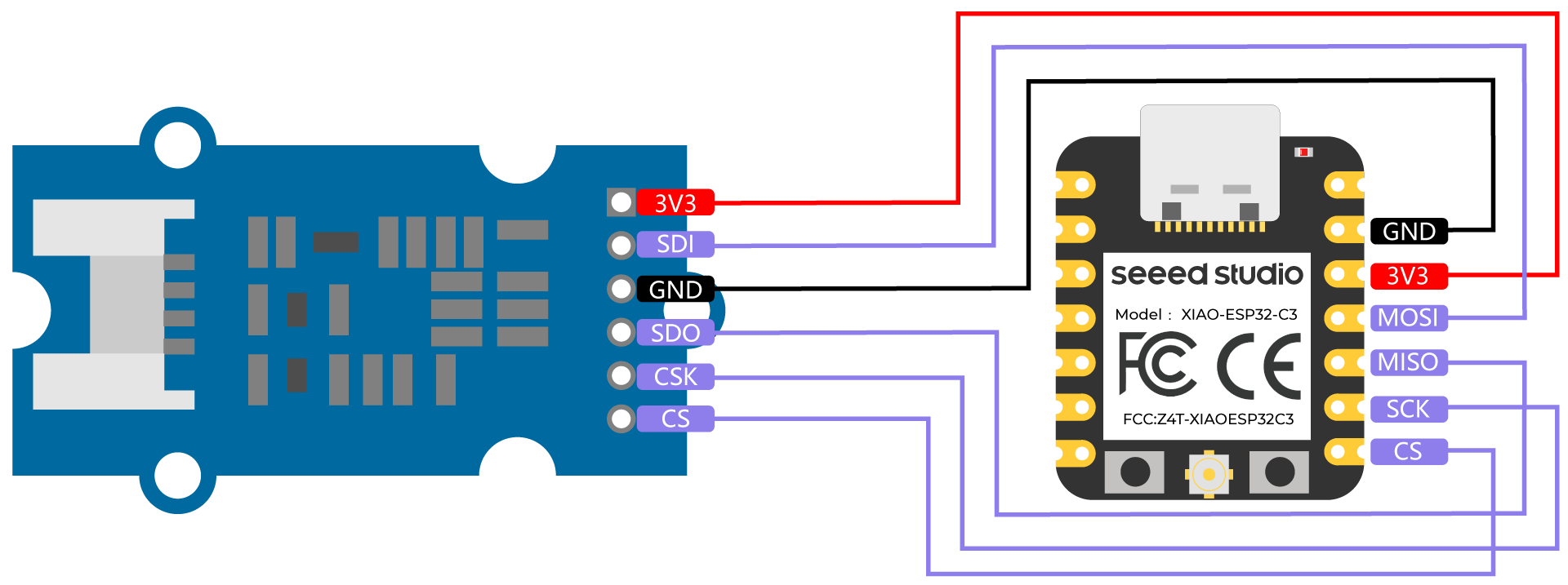
Conecte um Grove - High Precision Barometric Pressure Sensor (DPS310) ao XIAO ESP32C3 seguindo a conexão de hardware a seguir.
| Grove - High Precision Barometric Pressure Sensor (DPS310) | XIAO ESP32C3 |
|---|---|
| 3V3 | 3V3 |
| SDI | MOSI |
| GND | GND |
| SDO | MISO |
| CSK | SCK |
| CS | CS |
Configuração de software
- Passo 1. Baixe a Seeed_Arduino_DPS310 Library como um arquivo zip
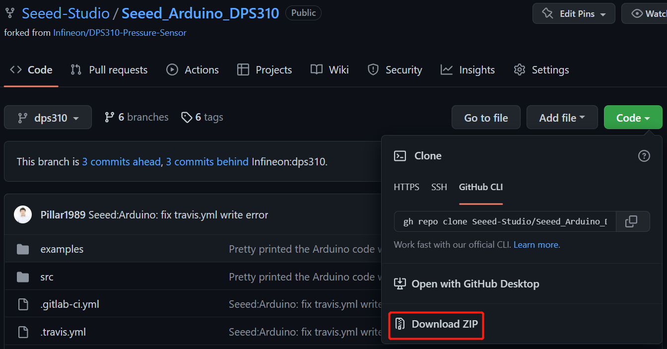
- Passo 2. Abra a Arduino IDE, navegue até
Sketch > Include Library > Add .ZIP Library...e abra o arquivo zip baixado

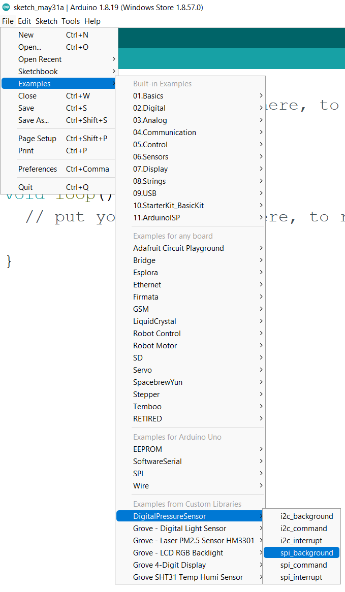
- Passo 3. Navegue até
File > Examples > DigitalPressureSensor > spi_backgroundpara abrir o exemplo spi_background
Como alternativa, você também pode copiar o código abaixo
#include <Dps310.h>

// Dps310 Opject
Dps310 Dps310PressureSensor = Dps310();

void setup() {
    //pin number of your slave select line
    //XMC2GO
    int16_t pin_cs = SS;
    //for XMC 1100 Bootkit  & XMC4700 Relax Kit uncomment the following line
    //int16_t pin_cs = 10;

    Serial.begin(9600);
    while (!Serial);


    //Call begin to initialize Dps310
    //The parameter pin_nr is the number of the CS pin on your Microcontroller
    Dps310PressureSensor.begin(SPI, pin_cs);

    //temperature measure rate (value from 0 to 7)
    //2^temp_mr temperature measurement results per second
    int16_t temp_mr = 2;
    //temperature oversampling rate (value from 0 to 7)
    //2^temp_osr internal temperature measurements per result
    //A higher value increases precision
    int16_t temp_osr = 2;
    //pressure measure rate (value from 0 to 7)
    //2^prs_mr pressure measurement results per second
    int16_t prs_mr = 2;
    //pressure oversampling rate (value from 0 to 7)
    //2^prs_osr internal pressure measurements per result
    //A higher value increases precision
    int16_t prs_osr = 2;
    //startMeasureBothCont enables background mode
    //temperature and pressure ar measured automatically
    //High precision and hgh measure rates at the same time are not available.
    //Consult Datasheet (or trial and error) for more information
    int16_t ret = Dps310PressureSensor.startMeasureBothCont(temp_mr, temp_osr, prs_mr, prs_osr);
    //Use one of the commented lines below instead to measure only temperature or pressure
    //int16_t ret = Dps310PressureSensor.startMeasureTempCont(temp_mr, temp_osr);
    //int16_t ret = Dps310PressureSensor.startMeasurePressureCont(prs_mr, prs_osr);


    if (ret != 0) {
        Serial.print("Init FAILED! ret = ");
        Serial.println(ret);
    } else {
        Serial.println("Init complete!");
    }
}


void loop() {
    uint8_t pressureCount = 20;
    float pressure[pressureCount];
    uint8_t temperatureCount = 20;
    float temperature[temperatureCount];

    //This function writes the results of continuous measurements to the arrays given as parameters
    //The parameters temperatureCount and pressureCount should hold the sizes of the arrays temperature and pressure when the function is called
    //After the end of the function, temperatureCount and pressureCount hold the numbers of values written to the arrays
    //Note: The Dps310 cannot save more than 32 results. When its result buffer is full, it won't save any new measurement results
    int16_t ret = Dps310PressureSensor.getContResults(temperature, temperatureCount, pressure, pressureCount);

    if (ret != 0) {
        Serial.println();
        Serial.println();
        Serial.print("FAIL! ret = ");
        Serial.println(ret);
    } else {
        Serial.println();
        Serial.println();
        Serial.print(temperatureCount);
        Serial.println(" temperature values found: ");
        for (int16_t i = 0; i < temperatureCount; i++) {
            Serial.print(temperature[i]);
            Serial.println(" degrees of Celsius");
        }

        Serial.println();
        Serial.print(pressureCount);
        Serial.println(" pressure values found: ");
        for (int16_t i = 0; i < pressureCount; i++) {
            Serial.print(pressure[i]);
            Serial.println(" Pascal");
        }
    }

    //Wait some time, so that the Dps310 can refill its buffer
    delay(10000);
}
- Passo 4. Faça o upload dos códigos e abra o Serial Monitor
Nota: Depois de fazer o upload dos códigos, eles não serão executados automaticamente até que você clique em Serial Monitor no canto superior direito da janela do Arduino.
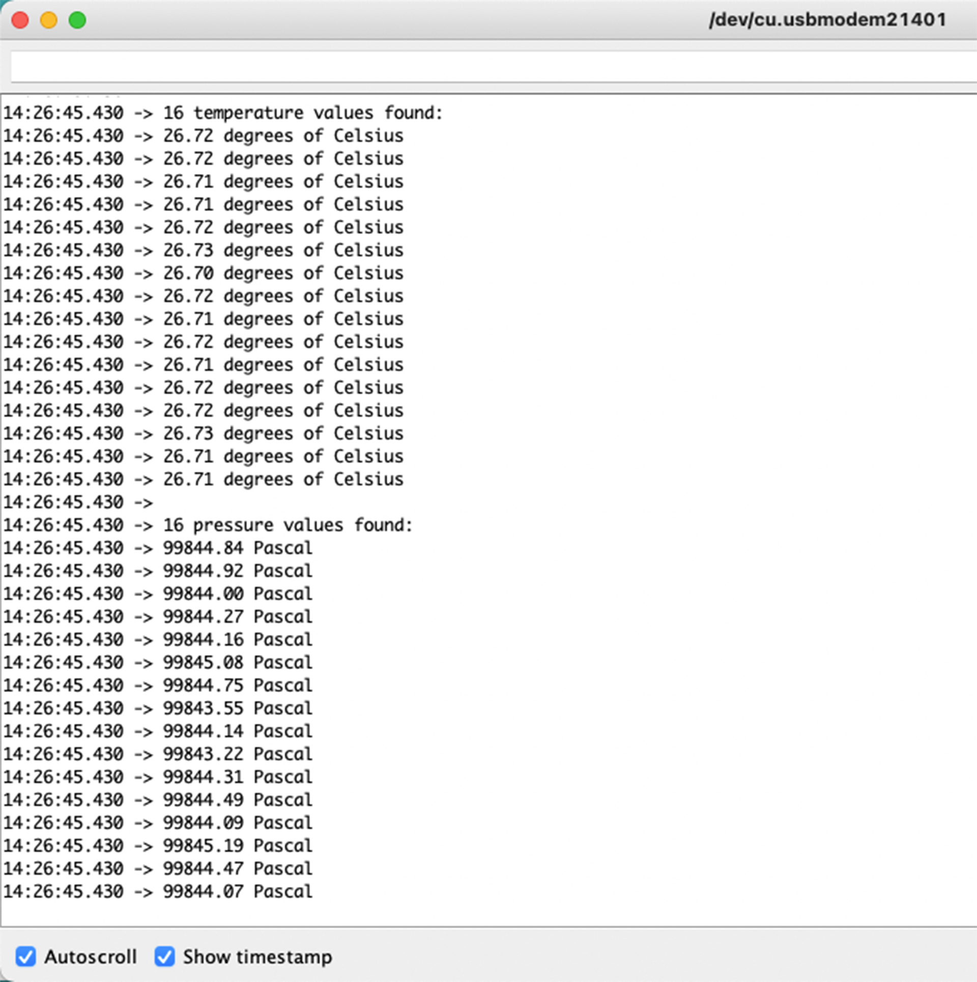
Agora você verá os dados de temperatura e pressão sendo exibidos um após o outro no monitor serial como acima!
Observação sobre a alocação de IO do XIAO ESP32C3
D9
O D9 do XIAO ESP32C3 está conectado ao GPIO9 (15) do ESP32-C3, ao resistor de pull-up (R6) e ao botão BOOT. O botão BOOT (e o botão RESET) permite alternar manualmente o modo de boot do ESP32-C3.
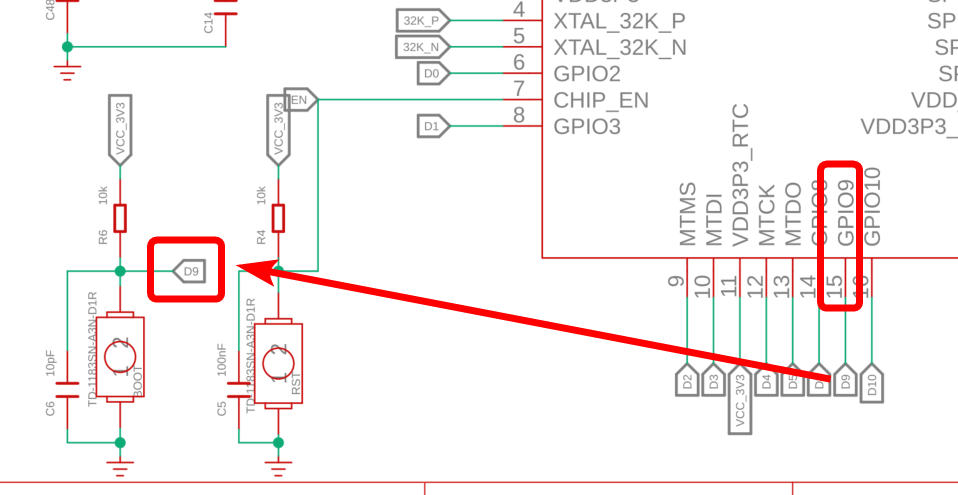
Ao pressionar o botão BOOT, o D9 é conectado ao GND. Portanto, é melhor usar o D9 como entrada de chave (switch).
D6
O D6 do XIAO ESP32C3 está conectado ao U0TXD (28) do ESP32-C3. O status de operação do bootloader de 1º/2º estágio é enviado como texto para o U0TXD.
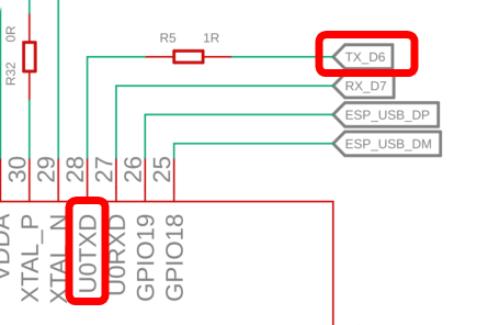
O D6 é configurado como saída UART na inicialização, portanto, se você usar o D6 como entrada, pode gerar acidentalmente uma corrente alta. Por isso, é recomendado usar o pino D6 apenas no modo de saída.
No entanto, como esse D6 é uma saída UART, você precisa ter cuidado com algumas coisas: uma é que ele fica em nível ALTO (HIGH) em modo de espera quando não está se comunicando. A outra é a saída de texto do bootloader de 1º/2º estágio. O sinal oscila entre ALTO/BAIXO (HIGH/LOW) imediatamente após a inicialização e deve ser compensado se necessário.
Portanto, tente não usar o D6. (Claro, não há problema em usá-lo depois que você o entender.)
D8
O D8 do Seeed Studio XIAO ESP32C3 está conectado ao GPIO8 (14) do ESP32-C3.
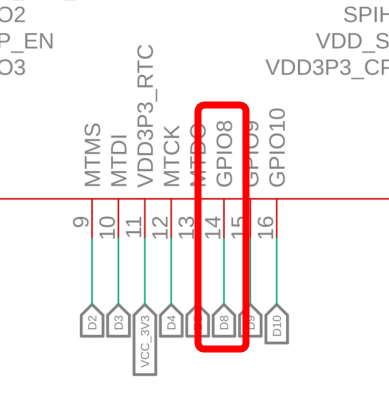
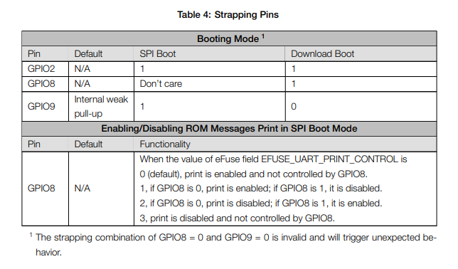
O GPIO8 é referenciado quando o modo de boot é definido para download boot mantendo pressionado o botão BOOT e deve estar em nível ALTO (HIGH) nesse momento. (Aqui está escrito: "The strapping combination of GPIO8 = 0 and GPIO9 = 0 is invalid and will trigger unexpected behaviour.")
Se você usar o download boot, adicione um resistor de pull-up para deixar o GPIO8 em nível ALTO (HIGH) no momento do boot.
Um agradecimento especial ao colega da SeeedJP matsujirushi por testar e contribuir com esta seção. Aqui está o link de referência para o artigo original.