Modos de Sono do XIAO ESP32S3 Sense
Aqui, apresentarei alguns exemplos simples para demonstrar o uso desses modos de sono de baixo consumo. Todas as placas ESP32 são versáteis, e a placa de desenvolvimento que estou usando neste contexto é a XIAO ESP32S3 Sense.
Visão Geral do Hardware
| Seeed Studio XIAO ESP32S3 Sense |
|---|
 |
Sono Profundo (Deep-Sleep)
Introdução
No modo Deep-Sleep, o ESP32 desliga as CPUs, a maior parte da RAM e todos os periféricos digitais temporizados a partir do APB_CLK. Os únicos componentes que permanecem ligados são:
- Controlador RTC
- Coprocessador ULP
- Memória RTC FAST
- Memória RTC SLOW
Métodos de Despertar
-
**Timer Wake-up:**O ESP32 pode acordar automaticamente após um tempo especificado configurando um temporizador.
-
**Touchpad Interrupt Wake-up:**O dispositivo pode ser despertado por atividade no touchpad, adequado para aplicações que exigem interação do usuário.
-
**External Wake-up:**O ESP32 pode ser acordado por sinais externos (por exemplo, pressionamento de botão), ideal para aplicações de baixo consumo.
-
**ULP Coprocessor Activity Wake-up:**O coprocessador ULP pode operar de forma independente, monitorando condições específicas e acordando a CPU principal para economizar energia.
-
**GPIO Wake-up:**O dispositivo pode ser despertado por mudanças nos estados dos pinos GPIO (alto ou baixo), oferecendo flexibilidade para vários sensores e periféricos.
Três exemplos simples do XIAO ESP32 S3 Sense usando o modo DeepSleep são apresentados abaixo.
Implementação do Código
- TimerWakeUP
- ExternalWakeUp
- TouchWakeUp
- SmoothBink_ULP
#define uS_TO_S_FACTOR 1000000ULL
#define TIME_TO_SLEEP  5

RTC_DATA_ATTR int bootCount = 0;

void print_wakeup_reason() {
  esp_sleep_wakeup_cause_t wakeup_reason;

  wakeup_reason = esp_sleep_get_wakeup_cause();

  switch (wakeup_reason) {
    case ESP_SLEEP_WAKEUP_EXT0:     Serial.println("Wakeup caused by external signal using RTC_IO"); break;
    case ESP_SLEEP_WAKEUP_EXT1:     Serial.println("Wakeup caused by external signal using RTC_CNTL"); break;
    case ESP_SLEEP_WAKEUP_TIMER:    Serial.println("Wakeup caused by timer"); break;
    case ESP_SLEEP_WAKEUP_TOUCHPAD: Serial.println("Wakeup caused by touchpad"); break;
    case ESP_SLEEP_WAKEUP_ULP:      Serial.println("Wakeup caused by ULP program"); break;
    default:                        Serial.printf("Wakeup was not caused by deep sleep: %d\n", wakeup_reason); break;
  }
}

void setup() {
  Serial.begin(115200);
  delay(1000);


  ++bootCount;
  Serial.println("Boot number: " + String(bootCount));


  print_wakeup_reason();


  esp_sleep_enable_timer_wakeup(TIME_TO_SLEEP * uS_TO_S_FACTOR);
  Serial.println("Setup ESP32 to sleep for every " + String(TIME_TO_SLEEP) + " Seconds");

  Serial.println("Going to sleep now");
  Serial.flush();
  esp_deep_sleep_start();
  Serial.println("This will never be printed");
}

void loop() {

}
Notas Detalhadas
#define uS_TO_S_FACTOR 1000000ULL
- Defina uma macro para converter microssegundos em segundos. 1000000ULL é o fator usado para converter microssegundos em segundos.
#define TIME_TO_SLEEP 5
- Defina uma macro que define o tempo pelo qual o ESP32 ficará em modo de sono, neste caso, 5 segundos.
RTC_DATA_ATTR int bootCount = 0;
- Declare uma variável inteira
bootCountcom o atributoRTC_DATA_ATTR, que permite que ela mantenha seu valor durante o sono profundo.
void print_wakeup_reason() {
- Defina uma função chamada
print_wakeup_reason()que irá imprimir o motivo pelo qual o ESP32 acordou.
esp_sleep_wakeup_cause_t wakeup_reason;
- Declare uma variável
wakeup_reasondo tipoesp_sleep_wakeup_cause_tpara armazenar a causa do evento de despertar.
wakeup_reason = esp_sleep_get_wakeup_cause();
- Chame a função
esp_sleep_get_wakeup_cause()para obter o motivo do despertar e atribuí-lo à variávelwakeup_reason.
  switch (wakeup_reason) {
    case ESP_SLEEP_WAKEUP_EXT0:     Serial.println("Wakeup caused by external signal using RTC_IO"); break;
    case ESP_SLEEP_WAKEUP_EXT1:     Serial.println("Wakeup caused by external signal using RTC_CNTL"); break;
    case ESP_SLEEP_WAKEUP_TIMER:    Serial.println("Wakeup caused by timer"); break;
    case ESP_SLEEP_WAKEUP_TOUCHPAD: Serial.println("Wakeup caused by touchpad"); break;
    case ESP_SLEEP_WAKEUP_ULP:      Serial.println("Wakeup caused by ULP program"); break;
    default:                        Serial.printf("Wakeup was not caused by deep sleep: %d\n", wakeup_reason); break;
}
ESP_SLEEP_WAKEUP_EXT0: Este motivo de despertar indica que o ESP32 acordou devido a um sinal externo detectado em um pino GPIO configurado para I/O de RTC (Relógio em Tempo Real). Isso é normalmente usado para despertar do sono quando um botão ou sensor é acionado.ESP_SLEEP_WAKEUP_EXT1: Isso indica que o despertar foi causado por um sinal externo em pinos GPIO gerenciados pelo controlador RTC. Diferente do EXT0, o EXT1 pode lidar com múltiplos pinos e pode acordar quando qualquer um dos pinos especificados mudar de estado (por exemplo, ir para nível baixo ou alto).ESP_SLEEP_WAKEUP_TIMER: Este motivo de despertar significa que o ESP32 acordou após uma duração de temporizador predefinida. Isso é útil para aplicações que precisam executar tarefas periódicas sem exigir interação do usuário.ESP_SLEEP_WAKEUP_TOUCHPAD: Isso indica que o ESP32 acordou devido a um evento no touchpad. Se um touchpad configurado para despertar detectar um toque, ele pode trazer o dispositivo para fora do modo de sono.ESP_SLEEP_WAKEUP_ULP: Este motivo de despertar significa que o despertar foi acionado por um programa ULP (Ultra-Low Power). Programas ULP podem ser executados enquanto a CPU principal está em sono profundo e podem acordar o ESP32 quando certas condições são atendidas, permitindo operação de baixo consumo com drenagem mínima da bateria.
++bootCount;
- Incremente a contagem de inicializações e imprima-a sempre que o dispositivo reiniciar.
print_wakeup_reason();
- Imprima o motivo do despertar do ESP32.
esp_sleep_enable_timer_wakeup(TIME_TO_SLEEP * uS_TO_S_FACTOR);
Serial.println("Setup ESP32 to sleep for every " + String(TIME_TO_SLEEP) + " Seconds");

Serial.println("Going to sleep now");
Serial.flush();
esp_deep_sleep_start();
Serial.println("This will never be printed");
esp_sleep_enable_timer_wakeup(TIME_TO_SLEEP * uS_TO_S_FACTOR);Habilite o temporizador para acordar o ESP32 após um tempo especificado.Serial.flush();Garanta que todos os dados seriais sejam enviados antes de entrar em modo de sono.esp_deep_sleep_start();Coloque o ESP32 em modo de sono profundo.
#include "driver/rtc_io.h"

#define BUTTON_PIN_BITMASK(GPIO) (1ULL << GPIO)
#define USE_EXT0_WAKEUP          1
#define WAKEUP_GPIO              GPIO_NUM_33
RTC_DATA_ATTR int bootCount = 0;


void print_wakeup_reason() {
  esp_sleep_wakeup_cause_t wakeup_reason;

  wakeup_reason = esp_sleep_get_wakeup_cause();

  switch (wakeup_reason) {
    case ESP_SLEEP_WAKEUP_EXT0:     Serial.println("Wakeup caused by external signal using RTC_IO"); break;
    case ESP_SLEEP_WAKEUP_EXT1:     Serial.println("Wakeup caused by external signal using RTC_CNTL"); break;
    case ESP_SLEEP_WAKEUP_TIMER:    Serial.println("Wakeup caused by timer"); break;
    case ESP_SLEEP_WAKEUP_TOUCHPAD: Serial.println("Wakeup caused by touchpad"); break;
    case ESP_SLEEP_WAKEUP_ULP:      Serial.println("Wakeup caused by ULP program"); break;
    default:                        Serial.printf("Wakeup was not caused by deep sleep: %d\n", wakeup_reason); break;
  }
}

void setup() {
  Serial.begin(115200);
  delay(1000);

  ++bootCount;
  Serial.println("Boot number: " + String(bootCount));

  print_wakeup_reason();

#if USE_EXT0_WAKEUP
  esp_sleep_enable_ext0_wakeup(WAKEUP_GPIO, 1);

  rtc_gpio_pullup_dis(WAKEUP_GPIO);
  rtc_gpio_pulldown_en(WAKEUP_GPIO);

#else
  esp_sleep_enable_ext1_wakeup_io(BUTTON_PIN_BITMASK(WAKEUP_GPIO), ESP_EXT1_WAKEUP_ANY_HIGH);

  rtc_gpio_pulldown_en(WAKEUP_GPIO);
  rtc_gpio_pullup_dis(WAKEUP_GPIO);
#endif

  Serial.println("Going to sleep now");
  esp_deep_sleep_start();
  Serial.println("This will never be printed");
}

void loop() {
}
Notas Detalhadas
#include "driver/rtc_io.h"
- Inclua o driver de I/O do RTC para acessar o GPIO de RTC.
#define BUTTON_PIN_BITMASK(GPIO) (1ULL << GPIO)
#define USE_EXT0_WAKEUP          1
#define WAKEUP_GPIO              GPIO_NUM_33
RTC_DATA_ATTR int bootCount = 0;
- 2 ^ GPIO_NUMBER em hexadecimal
- 1 = despertar EXT0, 0 = despertar EXT1
- Apenas I/O de RTC são permitidos - exemplo de pino do ESP32
  switch (wakeup_reason) {
    case ESP_SLEEP_WAKEUP_EXT0:     Serial.println("Wakeup caused by external signal using RTC_IO"); break;
    case ESP_SLEEP_WAKEUP_EXT1:     Serial.println("Wakeup caused by external signal using RTC_CNTL"); break;
    case ESP_SLEEP_WAKEUP_TIMER:    Serial.println("Wakeup caused by timer"); break;
    case ESP_SLEEP_WAKEUP_TOUCHPAD: Serial.println("Wakeup caused by touchpad"); break;
    case ESP_SLEEP_WAKEUP_ULP:      Serial.println("Wakeup caused by ULP program"); break;
    default:                        Serial.printf("Wakeup was not caused by deep sleep: %d\n", wakeup_reason); break;
}
ESP_SLEEP_WAKEUP_EXT0: Este motivo de despertar indica que o ESP32 acordou devido a um sinal externo detectado em um pino GPIO configurado para E/S de RTC (Relógio em Tempo Real). Isso é normalmente usado para despertar do modo de sono quando um botão ou sensor é acionado.ESP_SLEEP_WAKEUP_EXT1: Isso indica que o despertar foi causado por um sinal externo em pinos GPIO gerenciados pelo controlador RTC. Diferente do EXT0, o EXT1 pode lidar com múltiplos pinos e pode acordar quando qualquer um dos pinos especificados mudar de estado (por exemplo, ir para nível baixo ou alto).ESP_SLEEP_WAKEUP_TIMER: Este motivo de despertar significa que o ESP32 acordou após uma duração de temporizador predefinida. Isso é útil para aplicações que precisam executar tarefas periódicas sem exigir interação do usuário.ESP_SLEEP_WAKEUP_TOUCHPAD: Isso indica que o ESP32 acordou devido a um evento do touchpad. Se um touchpad configurado para despertar detectar um toque, ele pode tirar o dispositivo do modo de sono.ESP_SLEEP_WAKEUP_ULP: Este motivo de despertar significa que o despertar foi acionado por um programa ULP (Ultra-Low Power). Programas ULP podem ser executados enquanto a CPU principal está em deep sleep e podem acordar o ESP32 quando certas condições são atendidas, permitindo uma operação de baixo consumo com drenagem mínima da bateria.
  Serial.begin(115200);
  delay(1000);
  ++bootCount;
  Serial.println("Boot number: " + String(bootCount));
  print_wakeup_reason();
++bootCount;Incrementar o número de inicializações e imprimi-lo a cada rebootprint_wakeup_reason();Imprimir o motivo do despertar do ESP32
#if USE_EXT0_WAKEUP
  esp_sleep_enable_ext0_wakeup(WAKEUP_GPIO, 1);

  rtc_gpio_pullup_dis(WAKEUP_GPIO);
  rtc_gpio_pulldown_en(WAKEUP_GPIO);
esp_sleep_enable_ext0_wakeup(WAKEUP_GPIO, 1);Habilitar o despertar EXT0 no pino GPIO especificado quando ele for para nível alto.rtc_gpio_pullup_dis(WAKEUP_GPIO);Desabilitar o resistor de pull-up no pino GPIO de despertar.rtc_gpio_pulldown_en(WAKEUP_GPIO);Habilitar o resistor de pull-down no pino GPIO de despertar.
#else
  esp_sleep_enable_ext1_wakeup_io(BUTTON_PIN_BITMASK(WAKEUP_GPIO), ESP_EXT1_WAKEUP_ANY_HIGH);

  rtc_gpio_pulldown_en(WAKEUP_GPIO);
  rtc_gpio_pullup_dis(WAKEUP_GPIO);
-
esp_sleep_enable_ext1_wakeup_io(BUTTON_PIN_BITMASK(WAKEUP_GPIO), ESP_EXT1_WAKEUP_ANY_HIGH);DESPERTAR EXT1 -
rtc_gpio_pulldown_en(WAKEUP_GPIO);GPIO33 é ligado ao GND para poder acordar em nível ALTO -
rtc_gpio_pullup_dis(WAKEUP_GPIO);Desabilitar PULL_UP para permitir que ele acorde em nível ALTO -
esp_sleep_enable_ext1_wakeup_io(BUTTON_PIN_BITMASK(WAKEUP_GPIO), ESP_EXT1_WAKEUP_ANY_HIGH);Se você fosse usar ext1, você o usaria assim -
rtc_gpio_pulldown_en(WAKEUP_GPIO);GPIO33 é ligado ao GND para poder acordar em nível ALTO -
rtc_gpio_pullup_dis(WAKEUP_GPIO);Desabilitar PULL_UP para permitir que ele acorde em nível ALTO
  Serial.println("Going to sleep now");
  esp_deep_sleep_start();
  Serial.println("This will never be printed");
esp_deep_sleep_start();Colocar o ESP32 em modo de deep sleep.
#if CONFIG_IDF_TARGET_ESP32
#define THRESHOLD 40
#elif (CONFIG_IDF_TARGET_ESP32S2 || CONFIG_IDF_TARGET_ESP32S3)
#define THRESHOLD 5000
#else
#define THRESHOLD 500
#endif

RTC_DATA_ATTR int bootCount = 0;
touch_pad_t touchPin;

void print_wakeup_reason() {
  esp_sleep_wakeup_cause_t wakeup_reason;

  wakeup_reason = esp_sleep_get_wakeup_cause();

  switch (wakeup_reason) {
    case ESP_SLEEP_WAKEUP_EXT0:     Serial.println("Wakeup caused by external signal using RTC_IO"); break;
    case ESP_SLEEP_WAKEUP_EXT1:     Serial.println("Wakeup caused by external signal using RTC_CNTL"); break;
    case ESP_SLEEP_WAKEUP_TIMER:    Serial.println("Wakeup caused by timer"); break;
    case ESP_SLEEP_WAKEUP_TOUCHPAD: Serial.println("Wakeup caused by touchpad"); break;
    case ESP_SLEEP_WAKEUP_ULP:      Serial.println("Wakeup caused by ULP program"); break;
    default:                        Serial.printf("Wakeup was not caused by deep sleep: %d\n", wakeup_reason); break;
  }
}

void print_wakeup_touchpad() {
  touchPin = esp_sleep_get_touchpad_wakeup_status();

#if CONFIG_IDF_TARGET_ESP32
  switch (touchPin) {
    case 0:  Serial.println("Touch detected on GPIO 4"); break;
    case 1:  Serial.println("Touch detected on GPIO 0"); break;
    case 2:  Serial.println("Touch detected on GPIO 2"); break;
    case 3:  Serial.println("Touch detected on GPIO 15"); break;
    case 4:  Serial.println("Touch detected on GPIO 13"); break;
    case 5:  Serial.println("Touch detected on GPIO 12"); break;
    case 6:  Serial.println("Touch detected on GPIO 14"); break;
    case 7:  Serial.println("Touch detected on GPIO 27"); break;
    case 8:  Serial.println("Touch detected on GPIO 33"); break;
    case 9:  Serial.println("Touch detected on GPIO 32"); break;
    default: Serial.println("Wakeup not by touchpad"); break;
  }
#else
  if (touchPin < TOUCH_PAD_MAX) {
    Serial.printf("Touch detected on GPIO %d\n", touchPin);
  } else {
    Serial.println("Wakeup not by touchpad");
  }
#endif
}

void setup() {
  Serial.begin(115200);
  delay(1000);

  ++bootCount;
  Serial.println("Boot number: " + String(bootCount));

  print_wakeup_reason();
  print_wakeup_touchpad();

#if CONFIG_IDF_TARGET_ESP32

  touchSleepWakeUpEnable(T3, THRESHOLD);
  touchSleepWakeUpEnable(T7, THRESHOLD);

#else
  touchSleepWakeUpEnable(T3, THRESHOLD);

#endif

  Serial.println("Going to sleep now");
  esp_deep_sleep_start();
  Serial.println("This will never be printed");
}

void loop() {

}
Notas Detalhadas
#if CONFIG_IDF_TARGET_ESP32
#define THRESHOLD 40
#elif (CONFIG_IDF_TARGET_ESP32S2 || CONFIG_IDF_TARGET_ESP32S3)
#define THRESHOLD 5000
#else
#define THRESHOLD 500
#endif
- Verificar se o alvo é ESP32
- Definir o limite de sensibilidade ao toque para o ESP32
- Verificar se o alvo é ESP32S2 ou ESP32S3
- Definir um limite mais alto de sensibilidade ao toque para ESP32S2/S3
- Se o alvo não for nenhum dos anteriores
- Definir um limite padrão para outros alvos
RTC_DATA_ATTR int bootCount = 0; // Declare a variable to count boots, stored in RTC memory.
touch_pad_t touchPin; // Declare a variable to hold the touchpad pin status.

void print_wakeup_reason() { // Function to print the reason for waking up.
  esp_sleep_wakeup_cause_t wakeup_reason; // Variable to hold the wakeup reason.

  wakeup_reason = esp_sleep_get_wakeup_cause(); // Get the cause of the wakeup.
RTC_DATA_ATTR int bootCount = 0;Declarar uma variável para contar as inicializações, armazenada na memória RTC.touch_pad_t touchPin;Declarar uma variável para armazenar o status do pino do touchpad.void print_wakeup_reason()Função para imprimir o motivo do despertar.esp_sleep_wakeup_cause_t wakeup_reason;Variável para armazenar o motivo do despertar.wakeup_reason = esp_sleep_get_wakeup_cause();Obter a causa do despertar.
  switch (wakeup_reason) {
    case ESP_SLEEP_WAKEUP_EXT0:     Serial.println("Wakeup caused by external signal using RTC_IO"); break;
    case ESP_SLEEP_WAKEUP_EXT1:     Serial.println("Wakeup caused by external signal using RTC_CNTL"); break;
    case ESP_SLEEP_WAKEUP_TIMER:    Serial.println("Wakeup caused by timer"); break;
    case ESP_SLEEP_WAKEUP_TOUCHPAD: Serial.println("Wakeup caused by touchpad"); break;
    case ESP_SLEEP_WAKEUP_ULP:      Serial.println("Wakeup caused by ULP program"); break;
    default:                        Serial.printf("Wakeup was not caused by deep sleep: %d\n", wakeup_reason); break;
}
ESP_SLEEP_WAKEUP_EXT0: Este motivo de despertar indica que o ESP32 acordou devido a um sinal externo detectado em um pino GPIO configurado para E/S de RTC (Relógio em Tempo Real). Isso é normalmente usado para despertar do modo de sono quando um botão ou sensor é acionado.ESP_SLEEP_WAKEUP_EXT1: Isso indica que o despertar foi causado por um sinal externo em pinos GPIO gerenciados pelo controlador RTC. Diferente do EXT0, o EXT1 pode lidar com múltiplos pinos e pode acordar quando qualquer um dos pinos especificados mudar de estado (por exemplo, ir para nível baixo ou alto).ESP_SLEEP_WAKEUP_TIMER: Este motivo de despertar significa que o ESP32 acordou após uma duração de temporizador predefinida. Isso é útil para aplicações que precisam executar tarefas periódicas sem exigir interação do usuário.ESP_SLEEP_WAKEUP_TOUCHPAD: Isso indica que o ESP32 acordou devido a um evento do touchpad. Se um touchpad configurado para despertar detectar um toque, ele pode tirar o dispositivo do modo de sono.ESP_SLEEP_WAKEUP_ULP: Este motivo de despertar significa que o despertar foi acionado por um programa ULP (Ultra-Low Power). Programas ULP podem ser executados enquanto a CPU principal está em deep sleep e podem acordar o ESP32 quando certas condições são atendidas, permitindo uma operação de baixo consumo com drenagem mínima da bateria.
void print_wakeup_touchpad() {
  touchPin = esp_sleep_get_touchpad_wakeup_status();

#if CONFIG_IDF_TARGET_ESP32
  switch (touchPin) {
    case 0:  Serial.println("Touch detected on GPIO 4"); break;
    case 1:  Serial.println("Touch detected on GPIO 0"); break;
    case 2:  Serial.println("Touch detected on GPIO 2"); break;
    case 3:  Serial.println("Touch detected on GPIO 15"); break;
    case 4:  Serial.println("Touch detected on GPIO 13"); break;
    case 5:  Serial.println("Touch detected on GPIO 12"); break;
    case 6:  Serial.println("Touch detected on GPIO 14"); break;
    case 7:  Serial.println("Touch detected on GPIO 27"); break;
    case 8:  Serial.println("Touch detected on GPIO 33"); break;
    case 9:  Serial.println("Touch detected on GPIO 32"); break;
    default: Serial.println("Wakeup not by touchpad"); break;
  }
#else
  if (touchPin < TOUCH_PAD_MAX) {
    Serial.printf("Touch detected on GPIO %d\n", touchPin);
  } else {
    Serial.println("Wakeup not by touchpad");
  }
#endif
}
case 0:Toque detectado no GPIO 4.case 1:Toque detectado no GPIO 0.case 2:Toque detectado no GPIO 2.case 3:Toque detectado no GPIO 15.case 4:Toque detectado no GPIO 13.case 5:Toque detectado no GPIO 12.case 6:Toque detectado no GPIO 14.case 7:Toque detectado no GPIO 27.case 8:Toque detectado no GPIO 33.case 9:Toque detectado no GPIO 32.default:Caso padrão se nenhum toque for detectado.
void setup() {
  Serial.begin(115200);
  delay(1000);

  ++bootCount;
  Serial.println("Boot number: " + String(bootCount));

  print_wakeup_reason();
  print_wakeup_touchpad();

#if CONFIG_IDF_TARGET_ESP32

  touchSleepWakeUpEnable(T3, THRESHOLD);
  touchSleepWakeUpEnable(T7, THRESHOLD);

#else
  touchSleepWakeUpEnable(T3, THRESHOLD);

#endif

  Serial.println("Going to sleep now");
  esp_deep_sleep_start();
  Serial.println("This will never be printed");
}
-
++bootCount;Incrementar a contagem de inicializações. -
print_wakeup_reason();Imprimir o motivo do wakeup. -
print_wakeup_touchpad();Imprimir o status do wakeup por touchpad. -
#if CONFIG_IDF_TARGET_ESP32Verificar se o alvo é ESP32 -
touchSleepWakeUpEnable(T3, THRESHOLD);Habilitar wakeup por toque para T3 com o limite definido. -
touchSleepWakeUpEnable(T7, THRESHOLD);Habilitar wakeup por toque para T7 com o limite definido. -
touchSleepWakeUpEnable(T3, THRESHOLD);Habilitar wakeup por toque para T3 com o limite definido. -
esp_deep_sleep_start();Colocar o ESP32 em modo de sono profundo.
#include <Arduino.h> // Include the Arduino core library
#include "esp32/ulp.h" // Include ESP32 ULP-related library
#include "driver/rtc_io.h" // Include RTC GPIO driver library
#include "soc/rtc_io_reg.h" // Include RTC IO register definitions

#define RTC_dutyMeter 0 // Define the storage location for dutyMeter
#define RTC_dir       4 // Define the storage location for direction
#define RTC_fadeDelay 12 // Define the storage location for fadeDelay

uint32_t *fadeCycleDelay = &RTC_SLOW_MEM[RTC_fadeDelay]; // Point to the fadeDelay location in RTC_SLOW_MEM
#define ULP_START_OFFSET 32 // Define the starting offset for the ULP program

RTC_DATA_ATTR uint32_t ULP_Started = 0; // Variable to indicate if the ULP program has started
// Time-to-Sleep
#define uS_TO_S_FACTOR 1000000ULL // Conversion factor from microseconds to seconds
#define TIME_TO_SLEEP  5 // Time to enter deep sleep (in seconds)

void ulp_setup() { // ULP setup function
  if (ULP_Started) { // If ULP has already started, return
    return;
  }
  *fadeCycleDelay = 5; // Initialize fadeCycleDelay to 5
  ULP_Started = 1; // Mark ULP as started

  const gpio_num_t MeterPWMPin = GPIO_NUM_2; // Define the PWM pin
  rtc_gpio_init(MeterPWMPin); // Initialize GPIO
  rtc_gpio_set_direction(MeterPWMPin, RTC_GPIO_MODE_OUTPUT_ONLY); // Set the pin as output
  rtc_gpio_set_level(MeterPWMPin, 0); // Set the initial pin level to low

  const uint32_t MeterPWMBit = rtc_io_number_get(MeterPWMPin) + RTC_GPIO_OUT_DATA_S; // Get the bit for the PWM pin

  enum labels { // Define labels for the ULP program
    INIFINITE_LOOP,
    RUN_PWM,
    NEXT_PWM_CYCLE,
    PWM_ON,
    PWM_OFF,
    END_PWM_CYCLE,
    POSITIVE_DIR,
    DEC_DUTY,
    INC_DUTY,
  };

  // Define the ULP program
  const ulp_insn_t ulp_prog[] = {
    // Initial value setup
    I_MOVI(R0, 0), // Move 0 to register R0
    I_ST(R0, R0, RTC_dutyMeter), // Store the value of R0 in dutyMeter
    I_MOVI(R1, 1), // Move 1 to register R1
    I_ST(R1, R0, RTC_dir), // Store the value of R1 in dir

    M_LABEL(INIFINITE_LOOP), // Define the infinite loop label

    I_MOVI(R3, 0), // Move 0 to R3
    I_LD(R3, R3, RTC_fadeDelay), // Load the value from fadeDelay into R3
    M_LABEL(RUN_PWM), // Define the run PWM label

    I_MOVI(R0, 0), // Move 0 to R0
    I_LD(R0, R0, RTC_dutyMeter), // Load the value from dutyMeter into R0
    M_BL(NEXT_PWM_CYCLE, 1), // Branch to the next PWM cycle
    I_WR_REG(RTC_GPIO_OUT_W1TS_REG, MeterPWMBit, MeterPWMBit, 1), // Set the PWM pin high
    M_LABEL(PWM_ON), // Define the PWM ON label
    M_BL(NEXT_PWM_CYCLE, 1), // Branch to the next PWM cycle
    // I_DELAY(8), // Commented out delay instruction
    I_SUBI(R0, R0, 1), // Decrement R0 by 1
    M_BX(PWM_ON), // Go back to the PWM ON label

    M_LABEL(NEXT_PWM_CYCLE), // Define the next PWM cycle label
    I_MOVI(R0, 0), // Move 0 to R0
    I_LD(R0, R0, RTC_dutyMeter), // Load the value from dutyMeter into R0
    I_MOVI(R1, 100), // Move 100 to R1
    I_SUBR(R0, R1, R0), // R0 = R1 - R0
    M_BL(END_PWM_CYCLE, 1), // Branch to the end PWM cycle label
    I_WR_REG(RTC_GPIO_OUT_W1TC_REG, MeterPWMBit, MeterPWMBit, 1), // Set the PWM pin low
    M_LABEL(PWM_OFF), // Define the PWM OFF label
    M_BL(END_PWM_CYCLE, 1), // Branch to the end PWM cycle label
    // I_DELAY(8), // Commented out delay instruction
    I_SUBI(R0, R0, 1), // Decrement R0 by 1
    M_BX(PWM_OFF), // Go back to the PWM OFF label
    M_LABEL(END_PWM_CYCLE), // Define the end PWM cycle label

    I_SUBI(R3, R3, 1), // Decrement R3 by 1
    I_MOVR(R0, R3), // Move R3 to R0
    M_BGE(RUN_PWM, 1), // If R3 >= 0, branch to RUN_PWM

    I_MOVI(R1, 0), // Move 0 to R1
    I_LD(R1, R1, RTC_dutyMeter), // Load the value from dutyMeter into R1
    I_MOVI(R0, 0), // Move 0 to R0
    I_LD(R0, R0, RTC_dir), // Load the value from dir into R0

    M_BGE(POSITIVE_DIR, 1), // If R0 >= 0, branch to POSITIVE_DIR

    I_MOVR(R0, R1), // Move R1 to R0
    M_BGE(DEC_DUTY, 1), // If R1 >= 0, branch to DEC_DUTY
    I_MOVI(R3, 0), // Move 0 to R3
    I_MOVI(R2, 1), // Move 1 to R2
    I_ST(R2, R3, RTC_dir), // Store the value of R2 in dir
    M_BX(INC_DUTY), // Branch to INC_DUTY label
    M_LABEL(DEC_DUTY), // Define DEC_DUTY label
    I_SUBI(R0, R0, 2), // Decrement R0 by 2
    I_MOVI(R2, 0), // Move 0 to R2
    I_ST(R0, R2, RTC_dutyMeter), // Store the value of R0 in dutyMeter
    M_BX(INIFINITE_LOOP), // Go back to the infinite loop label

    M_LABEL(POSITIVE_DIR), // Define POSITIVE_DIR label

    I_MOVR(R0, R1), // Move R1 to R0
    M_BL(INC_DUTY, 100), // Branch to INC_DUTY label with parameter 100
    I_MOVI(R2, 0), // Move 0 to R2
    I_ST(R2, R2, RTC_dir), // Store the value of R2 in dir
    M_BX(DEC_DUTY), // Branch to DEC_DUTY label
    M_LABEL(INC_DUTY), // Define INC_DUTY label
    I_ADDI(R0, R0, 2), // Increment R0 by 2
    I_MOVI(R2, 0), // Move 0 to R2
    I_ST(R0, R2, RTC_dutyMeter), // Store the value of R0 in dutyMeter

    M_BX(INIFINITE_LOOP), // Go back to the infinite loop label
  };
  // Run the ULP program
  size_t size = sizeof(ulp_prog) / sizeof(ulp_insn_t); // Calculate the size of the ULP program
  ulp_process_macros_and_load(ULP_START_OFFSET, ulp_prog, &size); // Load the ULP program
  esp_sleep_pd_config(ESP_PD_DOMAIN_RTC_PERIPH, ESP_PD_OPTION_ON); // Configure power management for RTC peripherals
  ulp_run(ULP_START_OFFSET); // Start the ULP program
}

void setup() { // Arduino setup function
  Serial.begin(115200); // Initialize serial communication at 115200 baud rate

  ulp_setup(); // Call the ULP setup function
  Serial.printf("\nStarted smooth blink with delay %ld\n", *fadeCycleDelay); // Print startup information

  if (*fadeCycleDelay < 195) { // If fadeCycleDelay is less than 195
    *fadeCycleDelay += 10; // Increase fadeCycleDelay
  } else {
    *fadeCycleDelay = 5; // Otherwise, reset fadeCycleDelay to 5
  }
  Serial.println("Entering in Deep Sleep"); // Print entering deep sleep information
  esp_sleep_enable_timer_wakeup(TIME_TO_SLEEP * uS_TO_S_FACTOR /*/ 4*/); // Set timer wakeup
  esp_deep_sleep_start(); // Enter deep sleep
}

void loop() { // Arduino loop function
  // Empty loop
}
Para regravar o programa após entrar no modo de sono profundo, mantenha pressionado o botão de boot e depois pressione o botão de reset para reiniciar o ESP32.
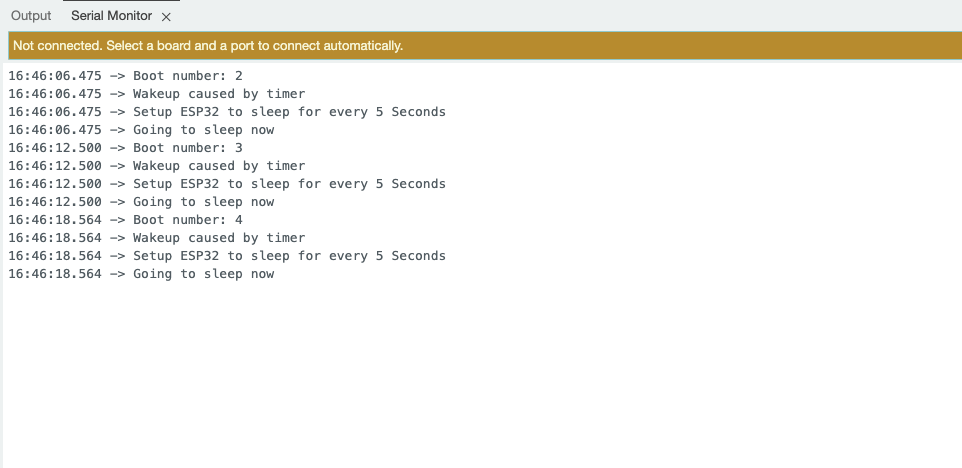
Exibição dos Resultados
Light-Sleep
Introdução
O modo Light Sleep é outro modo de baixo consumo de energia no ESP32 que permite ao dispositivo economizar energia enquanto ainda mantém um tempo de resposta rápido. Nesse modo, os núcleos da CPU são interrompidos, mas a RAM e alguns periféricos permanecem energizados, permitindo que o dispositivo acorde rapidamente em resposta a certos eventos.
O Light Sleep é ideal para aplicações que exigem baixo consumo de energia, mas que ainda precisam manter uma conexão com WiFi ou Bluetooth, pois permite que os módulos de comunicação sem fio permaneçam ativos.
Métodos de Wake-up
- Wake-up por Timer: O dispositivo pode acordar após um período de tempo especificado, permitindo a execução de tarefas periódicas.
- Wake-up por Interrupção Externa: O ESP32 pode ser acordado por sinais externos, como pressionamento de botões ou outras interrupções de hardware.
- Wake-up por Atividade de Rede: O dispositivo pode acordar em resposta a pacotes de rede recebidos, permitindo comunicação eficiente sem estar constantemente em estado ativo.
- Wake-up por GPIO: Pinos GPIO específicos podem ser configurados para acordar o dispositivo do Light Sleep quando um evento ocorre, como uma mudança de estado ou de sinal.
Implementação de Código
#include <freertos/FreeRTOS.h>
#include <freertos/task.h>

const int sleepTime = 10000;
const int ledPin = LED_BUILTIN;

void ledTask(void *pvParameters) {
  digitalWrite(ledPin, HIGH);
  Serial.println("LED is ON");
  vTaskDelay(pdMS_TO_TICKS(1000));
  digitalWrite(ledPin, LOW);
  Serial.println("LED is OFF");

  vTaskDelete(NULL);
}

void setup() {
  Serial.begin(115200);
  pinMode(ledPin, OUTPUT);
  Serial.println("Setup complete. Going to sleep...");
}

void loop() {
  esp_sleep_enable_timer_wakeup(sleepTime * 1000);
  Serial.println("Going to sleep now...");
  esp_light_sleep_start();

  xTaskCreate(ledTask, "LED Task", 2048, NULL, 1, NULL);

  delay(1000);
}
Notas Detalhadas
#include <freertos/FreeRTOS.h>
#include <freertos/task.h>
- Incldue FreeRTOS library
const int sleepTime = 10000;
const int ledPin = LED_BUILTIN;
- Definir o tempo de sono para 10 segundos
- Usar o pino do LED embutido
void ledTask(void *pvParameters):
- Defina uma tarefa FreeRTOS para controlar o estado do LED.
digitalWrite(ledPin, HIGH);
Serial.println("LED is ON");
vTaskDelay(pdMS_TO_TICKS(1000));
digitalWrite(ledPin, LOW);
Serial.println("LED is OFF");
vTaskDelete(NULL);
vTaskDelay(pdMS_TO_TICKS(1000));Keep the LED on for 1 secondvTaskDelete(NULL);Delete the current task
esp_sleep_enable_timer_wakeup(sleepTime * 1000);
Serial.println("Going to sleep now...");
esp_light_sleep_start();
xTaskCreate(ledTask, "LED Task", 2048, NULL, 1, NULL);
delay(1000);
esp_sleep_enable_timer_wakeup(sleepTime * 1000);Set timer for wakeupesp_light_sleep_start();Enter light sleep modexTaskCreate(ledTask, "LED Task", 2048, NULL, 1, NULL);Create LED control task
Resultados
Modem-Sleep
Introdução
O modo Modem Sleep é outro modo importante de baixo consumo de energia no ESP32, que é diferente do modo Deep Sleep. O modo Modem Sleep é otimizado principalmente para o módulo de comunicação sem fio do ESP32.
Nesse modo, o módulo WiFi/Bluetooth do ESP32 entra em estado de suspensão, enquanto os núcleos da CPU permanecem ativos. Isso permite que o ESP32 mantenha um certo nível de conectividade sem fio enquanto reduz significativamente o consumo de energia.
Métodos de Despertar
-
Despertar por temporizador
-
Despertar por interrupção externa
-
Despertar por tarefa
-
Despertar por atividade de rede
Implementação do Código
#include "WiFi.h"

void setup() {
    Serial.begin(115200);
    Serial.println("Connecting to WiFi...");

    WiFi.begin("****", "****");

    while (WiFi.status() != WL_CONNECTED) {
        delay(1000);
        Serial.println("Connecting...");
    }
    Serial.println("Connected to WiFi!");

    WiFi.setSleep(true);
    Serial.println("Modem-Sleep enabled.");
}

void loop() {

    Serial.println("Running...");

    delay(5000);

    WiFi.setSleep(false);
    Serial.println("Modem-Sleep disabled. WiFi is active.");

    if (WiFi.status() == WL_CONNECTED) {
        Serial.println("Still connected to WiFi.");
    } else {
        Serial.println("WiFi disconnected.");
    }

    delay(5000);
    WiFi.setSleep(true);
    Serial.println("Modem-Sleep enabled.");
}
Notas Detalhadas
#include "WiFi.h"
- Inclua a biblioteca WiFi para habilitar as funções de WiFi.
Serial.println("Connecting to WiFi...");
- Imprima uma mensagem indicando que a conexão ao WiFi está começando.
WiFi.begin("****", "****");
- Inicie a conexão à rede WiFi especificada.
    while (WiFi.status() != WL_CONNECTED) {
        delay(1000);
        Serial.println("Connecting...");
    }
    Serial.println("Connected to WiFi!");
- Faça o loop até conectar-se ao WiFi com sucesso.
WiFi.setSleep(true);
- Ative o modo modem sleep para economizar energia.
WiFi.setSleep(false);
- Desative o modo modem sleep para ativar o WiFi.
if (WiFi.status() == WL_CONNECTED) {
- Verifique o status do WiFi.
WiFi.setSleep(true);
- Ative novamente o modo modem sleep.
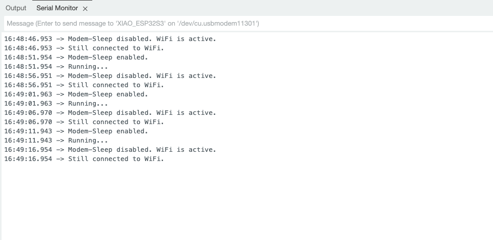
Resultados
Aplicação da Função de Suspensão
Com o simples exemplo acima, vamos agora dar um passo adiante e usar esses recursos de suspensão no sensor ESP32 S3 Sense.
Preparação de Software
Antes de começar este artigo, certifique-se de que você concluiu algumas preparações de instalação de software caso ainda não tenha utilizado todos os recursos de hardware no XIAO ESP32S3 Sense.
Aqui estão introduções a três funcionalidades, e você pode encontrar mais informações através dos seguintes links:
-
Micrphone Use: Aprenda como usar o microfone no XIAO ESP32S3 Sense para capturar níveis de som ambiente e gravar áudio.
-
MicroSD: Entenda como usar um cartão MicroSD para armazenamento de dados, garantindo que você possa salvar e recuperar arquivos em seus projetos.
-
Camera Use: Domine como usar o módulo de câmera no XIAO ESP32S3 Sense para tirar fotos e gravar vídeos.
Implementação do Código
- Deep-Sleep
- Light-Sleep
- Modem-Sleep
#include "esp_camera.h"
#include "FS.h"
#include "SD.h"
#include "SPI.h"

#define CAMERA_MODEL_XIAO_ESP32S3

#include "camera_pins.h"

unsigned long lastCaptureTime = 0;
int imageCount = 1;
bool camera_sign = false;
bool sd_sign = false;


void photo_save(const char * fileName) {
  camera_fb_t *fb = esp_camera_fb_get();
  if (!fb) {
    Serial.println("Failed to get camera frame buffer");
    return;
  }
  writeFile(SD, fileName, fb->buf, fb->len);

  esp_camera_fb_return(fb);

  Serial.println("Photo saved to file");
}

void writeFile(fs::FS &fs, const char * path, uint8_t * data, size_t len){
    Serial.printf("Writing file: %s\r\n", path);

    File file = fs.open(path, FILE_WRITE);
    if (!file) {
        Serial.println("Failed to open file for writing");
        return;
    }
    if (file.write(data, len) == len) {
        Serial.println("File written");
    } else {
        Serial.println("Write failed");
    }
    file.close();
}

void setup() {
  Serial.begin(115200);
  while (!Serial);

  camera_config_t config;
  config.ledc_channel = LEDC_CHANNEL_0;
  config.ledc_timer = LEDC_TIMER_0;
  config.pin_d0 = Y2_GPIO_NUM;
  config.pin_d1 = Y3_GPIO_NUM;
  config.pin_d2 = Y4_GPIO_NUM;
  config.pin_d3 = Y5_GPIO_NUM;
  config.pin_d4 = Y6_GPIO_NUM;
  config.pin_d5 = Y7_GPIO_NUM;
  config.pin_d6 = Y8_GPIO_NUM;
  config.pin_d7 = Y9_GPIO_NUM;
  config.pin_xclk = XCLK_GPIO_NUM;
  config.pin_pclk = PCLK_GPIO_NUM;
  config.pin_vsync = VSYNC_GPIO_NUM;
  config.pin_href = HREF_GPIO_NUM;
  config.pin_sscb_sda = SIOD_GPIO_NUM;
  config.pin_sscb_scl = SIOC_GPIO_NUM;
  config.pin_pwdn = PWDN_GPIO_NUM;
  config.pin_reset = RESET_GPIO_NUM;
  config.xclk_freq_hz = 20000000;
  config.frame_size = FRAMESIZE_UXGA;
  config.pixel_format = PIXFORMAT_JPEG;
  config.grab_mode = CAMERA_GRAB_WHEN_EMPTY;
  config.fb_location = CAMERA_FB_IN_PSRAM;
  config.jpeg_quality = 12;
  config.fb_count = 1;

  esp_err_t err = esp_camera_init(&config);
  if (err != ESP_OK) {
    Serial.printf("Camera init failed with error 0x%x", err);
    return;
  }

  camera_sign = true;

  if (!SD.begin(21)) {
    Serial.println("Card Mount Failed");
    return;
  }

  uint8_t cardType = SD.cardType();

  if (cardType == CARD_NONE) {
    Serial.println("No SD card attached");
    return;
  }

  Serial.print("SD Card Type: ");
  if (cardType == CARD_MMC) {
    Serial.println("MMC");
  } else if (cardType == CARD_SD) {
    Serial.println("SDSC");
  } else if (cardType == CARD_SDHC) {
    Serial.println("SDHC");
  } else {
    Serial.println("UNKNOWN");
  }

  sd_sign = true;

  Serial.println("Photos will begin shortly, please be ready.");
}

void loop() {
  if (camera_sign && sd_sign) {
    unsigned long now = millis();

    if ((now - lastCaptureTime) >= 60000) {
      char filename[32];
      sprintf(filename, "/image%d.jpg", imageCount);
      photo_save(filename);
      Serial.printf("Saved picture: %s\r\n", filename);
      Serial.println("Entering deep sleep for 10 seconds...");

      esp_sleep_enable_timer_wakeup(10000000);
      esp_deep_sleep_start();

    }
  }
}
Notas Detalhadas
Este código implementa um sistema de captura de imagens baseado no módulo de câmera do ESP32, que pode tirar automaticamente uma foto a cada 60 segundos e salvá-la no cartão SD. Na função void setup(), a câmera e o cartão SD são inicializados e o status do dispositivo é confirmado; na função void loop(), verifica-se se a câmera pode tirar uma foto e, se a condição for atendida, a função photo_save() é chamada para salvar a imagem e, após o salvamento, o dispositivo entra em um estado de deep sleep por 10 segundos para economizar energia.
#include <ESP_I2S.h>
#include <freertos/FreeRTOS.h>
#include <freertos/task.h>

I2SClass I2S;

const int sleepTime = 10000;

void i2sTask(void *pvParameters) {
  Serial.println("start collecting");
  for (int i = 0; i < 10; i++) {
    int sample = I2S.read();
    if (sample && sample != -1 && sample != 1) {
      Serial.println(sample);
    }
    vTaskDelay(pdMS_TO_TICKS(1000));
  }
  vTaskDelay(pdMS_TO_TICKS(3000));
  vTaskDelete(NULL);
}

void setup() {
  Serial.begin(115200);
  while (!Serial) {
    ;
  }

  I2S.setPinsPdmRx(42, 41);

  if (!I2S.begin(I2S_MODE_PDM_RX, 16000, I2S_DATA_BIT_WIDTH_16BIT, I2S_SLOT_MODE_MONO)) {
    Serial.println("Failed to initialize I2S!");
    while (1);
  }
}

void loop() {
  esp_sleep_enable_timer_wakeup(sleepTime * 1000);
  xTaskCreate(i2sTask, "I2S Task", 2048, NULL, 1, NULL);

  Serial.println("Going to sleep now...");
  esp_light_sleep_start();

  delay(1000);
}
Notas Detalhadas
Este código implementa a função de captura de dados de áudio usando a interface I2S. Na função void setup(), a porta serial e a interface I2S são inicializadas; na função void loop(), o temporizador de despertar é habilitado e uma tarefa void i2sTask(void *pvParameters) é criada, que é responsável por ler amostras de áudio e imprimir dados válidos a cada segundo. Após a tarefa ser executada 10 vezes, ela atrasa por 3 segundos e então se exclui.
#include "esp_camera.h"
#include <WiFi.h>

#define CAMERA_MODEL_XIAO_ESP32S3
#include "camera_pins.h"

const char *ssid = "******";
const char *password = "******";

void startCameraServer();
void setupLedFlash(int pin);

unsigned long lastCameraOperationTime = 0;
const unsigned long sleepDelay = 10000;

void setup() {
  Serial.begin(115200);
  Serial.setDebugOutput(true);
  Serial.println();

  camera_config_t config;
  config.ledc_channel = LEDC_CHANNEL_0;
  config.ledc_timer = LEDC_TIMER_0;
  config.pin_d0 = Y2_GPIO_NUM;
  config.pin_d1 = Y3_GPIO_NUM;
  config.pin_d2 = Y4_GPIO_NUM;
  config.pin_d3 = Y5_GPIO_NUM;
  config.pin_d4 = Y6_GPIO_NUM;
  config.pin_d5 = Y7_GPIO_NUM;
  config.pin_d6 = Y8_GPIO_NUM;
  config.pin_d7 = Y9_GPIO_NUM;
  config.pin_xclk = XCLK_GPIO_NUM;
  config.pin_pclk = PCLK_GPIO_NUM;
  config.pin_vsync = VSYNC_GPIO_NUM;
  config.pin_href = HREF_GPIO_NUM;
  config.pin_sccb_sda = SIOD_GPIO_NUM;
  config.pin_sccb_scl = SIOC_GPIO_NUM;
  config.pin_pwdn = PWDN_GPIO_NUM;
  config.pin_reset = RESET_GPIO_NUM;
  config.xclk_freq_hz = 20000000;
  config.frame_size = FRAMESIZE_UXGA;
  config.pixel_format = PIXFORMAT_JPEG;
  config.grab_mode = CAMERA_GRAB_WHEN_EMPTY;
  config.fb_location = CAMERA_FB_IN_PSRAM;
  config.jpeg_quality = 12;
  config.fb_count = 1;

  if (config.pixel_format == PIXFORMAT_JPEG) {
    if (psramFound()) {
      config.jpeg_quality = 10;
      config.fb_count = 2;
      config.grab_mode = CAMERA_GRAB_LATEST;
    } else {
      config.frame_size = FRAMESIZE_SVGA;
      config.fb_location = CAMERA_FB_IN_DRAM;
    }
  } else {
    config.frame_size = FRAMESIZE_240X240;
#if CONFIG_IDF_TARGET_ESP32S3
    config.fb_count = 2;
#endif
  }

#if defined(CAMERA_MODEL_ESP_EYE)
  pinMode(13, INPUT_PULLUP);
  pinMode(14, INPUT_PULLUP);
#endif

  esp_err_t err = esp_camera_init(&config);
  if (err != ESP_OK) {
    Serial.printf("Camera init failed with error 0x%x", err);
    return;
  }

  sensor_t *s = esp_camera_sensor_get();
  if (s->id.PID == OV3660_PID) {
    s->set_vflip(s, 1);
    s->set_brightness(s, 1);
    s->set_saturation(s, -2);
  }
  if (config.pixel_format == PIXFORMAT_JPEG) {
    s->set_framesize(s, FRAMESIZE_QVGA);
  }

#if defined(CAMERA_MODEL_M5STACK_WIDE) || defined(CAMERA_MODEL_M5STACK_ESP32CAM)
  s->set_vflip(s, 1);
  s->set_hmirror(s, 1);
#endif

#if defined(CAMERA_MODEL_ESP32S3_EYE)
  s->set_vflip(s, 1);
#endif

#if defined(LED_GPIO_NUM)
  setupLedFlash(LED_GPIO_NUM);
#endif

  WiFi.begin(ssid, password);
  WiFi.setSleep(false);

  while (WiFi.status() != WL_CONNECTED) {
    delay(500);
    Serial.print(".");
  }
  Serial.println("");
  Serial.println("WiFi connected");

  startCameraServer();

  Serial.print("Camera Ready! Use 'http://");
  Serial.print(WiFi.localIP());
  Serial.println("' to connect");
}

void loop() {
  delay(10000);

  if (WiFi.getSleep()) {
    Serial.println("WiFi is in sleep mode.");
  } else {
    Serial.println("WiFi is active.");
  }

  if (millis() - lastCameraOperationTime > sleepDelay) {
    WiFi.setSleep(true);
    Serial.println("No camera operation. WiFi is now in sleep mode.");
  } else {
    WiFi.setSleep(false);
  }
  cameraOperation();
}

void cameraOperation() {
  lastCameraOperationTime = millis();
}
Notas detalhadas
Este código implementa o uso do módulo de câmera ESP32 para captura de imagem e conexão via Wi-Fi. Na função void setup(), a porta serial, a câmera e a conexão Wi-Fi são inicializadas; se a inicialização for bem-sucedida, o programa imprime o endereço Wi-Fi para o usuário se conectar. Na função void loop(), o código verifica o status do Wi-Fi a cada 10 segundos, se não houver operação da câmera, o Wi-Fi será colocado em modo de suspensão para economizar energia. Cada chamada para a função cameraOperation() atualiza o horário da última operação para garantir que o Wi-Fi permaneça conectado durante o evento.
Esses códigos não podem ser usados diretamente, você precisa adicionar o arquivo de cabeçalho da câmera, por favor verifique o exemplo acima sobre o XIAO ESP32 S3.
Para concluir
Por que usar o modo Deep Sleep
maximizar a economia de energia sem comprometer a funcionalidade, a fim de estender a vida útil da bateria do dispositivo. Cenários adequados: Aplicações em que a duração da bateria é crucial, como nós de sensores remotos, dispositivos vestíveis e outros dispositivos IoT de baixo consumo. Embora o tempo de despertar seja relativamente lento, essa compensação vale a pena.
Por que usar o modo Modem Sleep
otimizar o consumo de energia do módulo de comunicação sem fio, mantendo ainda assim a conectividade de rede. Cenários adequados: Aplicações que precisam manter a conexão de rede, mas também exigem baixo consumo de energia, como dispositivos IoT que operam intermitentemente. O Modem Sleep pode reduzir significativamente o consumo de energia do módulo sem fio, ao mesmo tempo em que fornece uma resposta de despertar rápida.
Em resumo
esses três modos de suspensão oferecem aos desenvolvedores diferentes opções de compromisso entre energia e desempenho, que podem ser escolhidas de forma flexível com base nos requisitos específicos da aplicação. Para dispositivos com requisitos de duração de bateria, o modo Deep Sleep é uma boa escolha; e para dispositivos IoT que precisam manter conectividade de rede, o modo Modem Sleep é a escolha ideal.
Suporte Técnico & Discussão de Produto
Obrigado por escolher nossos produtos! Estamos aqui para lhe fornecer diferentes tipos de suporte para garantir que sua experiência com nossos produtos seja a mais tranquila possível. Oferecemos vários canais de comunicação para atender a diferentes preferências e necessidades.