Controle de GPIO do reSpeaker Flex com Xiao ESP32S3
Objetivo
Este guia explica como ler e controlar pinos GPIO no processador de voz XVF3800 usando a interface I2C. Você aprenderá a:
- Ler os estados dos pinos GPI e GPO
- Entender os mapeamentos de GPIO e sua finalidade
| reSpeaker Flex XVF3800 Linear com XIAO ESP32S3 | reSpeaker Flex XVF3800 Circular com XIAO ESP32S3 | |
|---|---|---|
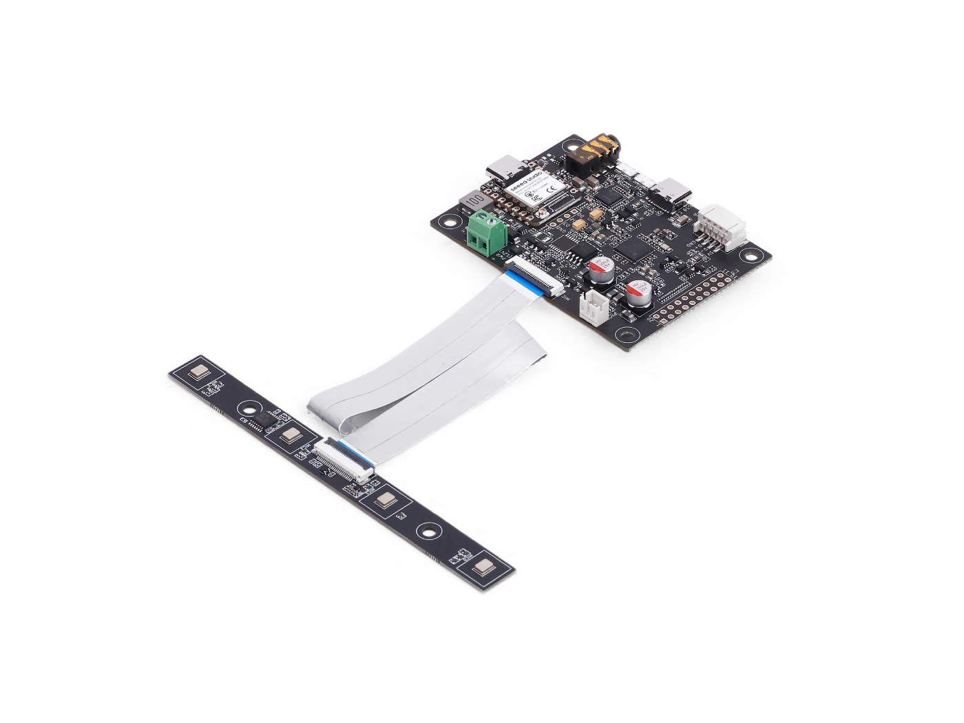 | 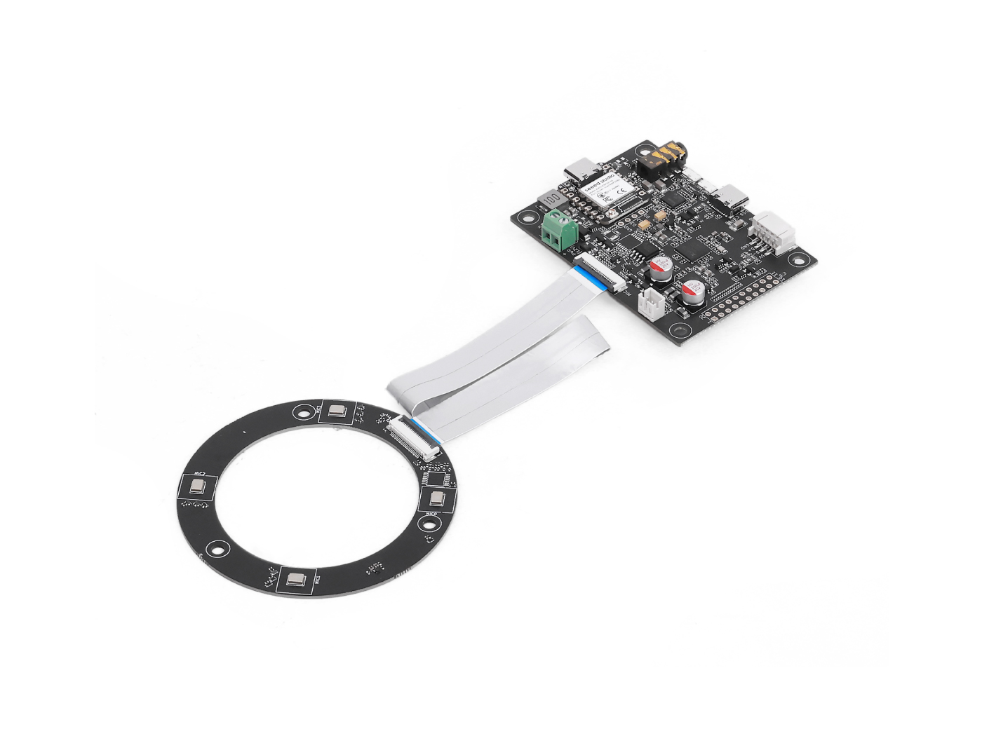 | |
Visão geral de GPIO
| Nome do pino | Direção | Função |
|---|---|---|
| X1D09 | Entrada (RO) | Status do botão de boot / GPI0 |
| X1D13 | Entrada (RO) | Flutuante / GPI1 |
| X1D34 | Entrada (RO) | Flutuante / GPI2 |
| X0D11 | Saída (RW) | Flutuante / GPO, compartilhado com SPI MOSI |
| X0D30 | Saída (RW) | Controle de SD/FAULT |
| X0D31 | Saída (RW) | Controle de PA / amplificador |
| X0D32 | Saída (RW) | XMOS GPIO 1 |
| X0D33 | Saída (RW) | XMOS GPIO 2 |
| X0D39 | Saída (RW) | Flutuante / GPO, compartilhado com SPI MISO |
Ler estados dos pinos GPO
Objetivo: Verificar os níveis lógicos de todos os GPIOs com capacidade de saída (GPOs). Destaques do código:
- Envia uma requisição de leitura usando:
- ID de recurso: 20 (GPO)
- ID de comando: 0 (GPO_READ_VALUES)
- Lê os estados de 5 pinos GPO na ordem: X0D11 → X0D30 → X0D31 → X0D33 → X0D39
- Inclui um byte de status para validar a resposta
#include <Wire.h>

#define XMOS_ADDR 0x2C  // I2C 7-bit address

#define GPO_SERVICER_RESID 20
#define GPO_SERVICER_RESID_GPO_READ_VALUES 0
#define GPO_GPO_READ_NUM_BYTES 5

void setup() {
  Serial.begin(115200);
  while (!Serial);
  Wire.begin();
  delay(1000);
  Serial.println("XVF3800 GPO Read Test Starting...");
}

void loop() {
  uint8_t gpo_values[GPO_GPO_READ_NUM_BYTES] = {0};
  uint8_t status = 0xFF;

  bool success = read_gpo_values(gpo_values, &status);

  if (success) {
    Serial.print("I2C Communication SUCCESS. Status byte: 0x");
    Serial.print(status, HEX);
    Serial.print(" | GPO Output Values: ");
    for (uint8_t i = 0; i < GPO_GPO_READ_NUM_BYTES; i++) {
      Serial.print("0x");
      Serial.print(gpo_values[i], HEX);
      Serial.print(" ");
    }
    Serial.println();
  } else {
    Serial.println("Failed to read GPO values.");
  }

  delay(1000);
}

bool read_gpo_values(uint8_t *buffer, uint8_t *status) {
  const uint8_t resid = GPO_SERVICER_RESID;
  const uint8_t cmd = GPO_SERVICER_RESID_GPO_READ_VALUES | 0x80;
  const uint8_t read_len = GPO_GPO_READ_NUM_BYTES;

  // Step 1: Write command
  Wire.beginTransmission(XMOS_ADDR);
  Wire.write(resid);
  Wire.write(cmd);
  Wire.write(read_len + 1);
  uint8_t result = Wire.endTransmission();

  if (result != 0) {
    Serial.print("I2C Write Error: ");
    Serial.println(result);
    return false;
  }

  // Step 2: Read response (status + payload)
  Wire.requestFrom(XMOS_ADDR, (uint8_t)(read_len + 1));
  if (Wire.available() < read_len + 1) {
    Serial.println("I2C Read Error: Not enough data received.");
    return false;
  }

  *status = Wire.read();
  for (uint8_t i = 0; i < read_len; i++) {
    buffer[i] = Wire.read();
  }

  return true;
}
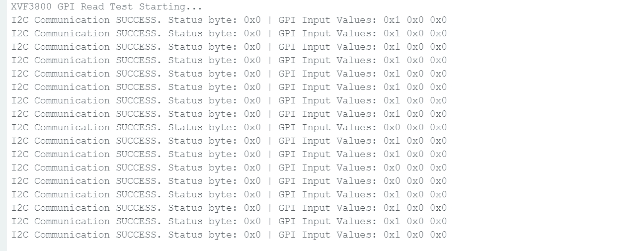
Ler estados dos pinos GPI
Objetivo: Verificar os estados dos GPIOs com capacidade de entrada (por exemplo, status do botão de mute). Destaques do código:
- Envia comando para:
- ID de recurso: 36 (IO_CONFIG)
- ID de comando: 6 (GPI_VALUE_ALL)
- Recebe 3 GPI representando o estado de X1D09, X1D13 e X1D34
#include <Wire.h>

#define XMOS_ADDR 0x2C  // I2C 7-bit address of XVF3800

// Resource and command IDs for GPI
#define IO_CONFIG_SERVICER_RESID 36
#define IO_CONFIG_SERVICER_RESID_GPI_READ_VALUES 0
#define GPI_READ_NUM_BYTES 3   // From header: IO_CONFIG_SERVICER_RESID_GPI_READ_VALUES_NUM_VALUES

void setup() {
  Serial.begin(115200);
  while (!Serial);
  Wire.begin();
  delay(1000);
  Serial.println("XVF3800 GPI Read Test Starting...");
}

void loop() {
  uint8_t gpi_values[GPI_READ_NUM_BYTES] = {0};
  uint8_t status = 0xFF;

  bool success = read_gpi_values(gpi_values, &status);

  if (success) {
    Serial.print("I2C Communication SUCCESS. Status byte: 0x");
    Serial.print(status, HEX);
    Serial.print(" | GPI Input Values: ");
    for (uint8_t i = 0; i < GPI_READ_NUM_BYTES; i++) {
      Serial.print("0x");
      Serial.print(gpi_values[i], HEX);
      Serial.print(" ");
    }
    Serial.println();
  } else {
    Serial.println("Failed to read GPI values.");
  }

  delay(1000);
}

bool read_gpi_values(uint8_t *buffer, uint8_t *status) {
  const uint8_t resid = IO_CONFIG_SERVICER_RESID;
  const uint8_t cmd = IO_CONFIG_SERVICER_RESID_GPI_READ_VALUES | 0x80;  // Read command
  const uint8_t read_len = GPI_READ_NUM_BYTES;

  // Step 1: Send the command
  Wire.beginTransmission(XMOS_ADDR);
  Wire.write(resid);
  Wire.write(cmd);
  Wire.write(read_len + 1);  // +1 for status byte
  uint8_t result = Wire.endTransmission();

  if (result != 0) {
    Serial.print("I2C Write Error: ");
    Serial.println(result);
    return false;
  }

  // Step 2: Read response (status + payload)
  Wire.requestFrom(XMOS_ADDR, (uint8_t)(read_len + 1));
  if (Wire.available() < read_len + 1) {
    Serial.println("I2C Read Error: Not enough data received.");
    return false;
  }

  *status = Wire.read();  // first byte is status
  for (uint8_t i = 0; i < read_len; i++) {
    buffer[i] = Wire.read();
  }

  return true;
}
Assim que você pressionar o botão de boot, o estado será alterado.
Suporte técnico e discussão sobre o produto
Obrigado por escolher nossos produtos! Estamos aqui para oferecer diferentes tipos de suporte para garantir que sua experiência com nossos produtos seja a mais tranquila possível. Oferecemos vários canais de comunicação para atender a diferentes preferências e necessidades.