Controlando o GPIO do reSpeaker XVF3800 via XIAO ESP32-S3
Objetivo
Este guia explica como ler e controlar pinos GPIO no processador de voz XVF3800 usando a interface I2C. Você aprenderá a:
- Ler os estados dos pinos GPI e GPO
- Controlar pinos de saída (por exemplo, silenciar microfone, controlar LED, amplificador)
- Entender os mapeamentos de GPIO e sua finalidade
Visão geral de GPIO
O reSpeaker XVF3800 expõe 3 pinos de entrada (GPI) e 5 pinos de saída (GPO) para controle externo. Você pode usá-los para ler estados de botões ou controlar hardware como o LED de mute, o amplificador ou LEDs.
| Nome do pino | Direção | Função |
|---|---|---|
| X1D09 | Entrada (RO) | Status do botão de mute (alto quando liberado) |
| X1D13 | Entrada (RO) | Flutuante |
| X1D34 | Entrada (RO) | Flutuante |
| X0D11 | Saída (RW) | Flutuante |
| X0D30 | Saída (RW) | Controle de LED de mute + mute do microfone (alto = mute) |
| X0D31 | Saída (RW) | Habilitação do amplificador (baixo = habilitado) |
| X0D33 | Saída (RW) | Controle de energia do LED WS2812 (alto = ligado) |
| X0D39 | Saída (RW) | Flutuante |
Ler estados dos pinos GPO
Objetivo: Verificar os níveis lógicos de todos os GPIOs com capacidade de saída (GPOs). Destaques do código:
- Envia uma solicitação de leitura usando:
- ID de recurso: 20 (GPO)
- ID de comando: 0 (GPO_READ_VALUES)
- Lê estados de 5 pinos GPO na ordem: X0D11 → X0D30 → X0D31 → X0D33 → X0D39
- Inclui um byte de status para validar a resposta
#include <Wire.h>
#define XMOS_ADDR 0x2C // I2C 7-bit address
#define GPO_SERVICER_RESID 20
#define GPO_SERVICER_RESID_GPO_READ_VALUES 0
#define GPO_GPO_READ_NUM_BYTES 5
void setup() {
Serial.begin(115200);
while (!Serial);
Wire.begin();
delay(1000);
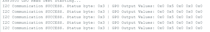
Serial.println("XVF3800 GPO Read Test Starting...");
}
void loop() {
uint8_t gpo_values[GPO_GPO_READ_NUM_BYTES] = {0};
uint8_t status = 0xFF;
bool success = read_gpo_values(gpo_values, &status);
if (success) {
Serial.print("I2C Communication SUCCESS. Status byte: 0x");
Serial.print(status, HEX);
Serial.print(" | GPO Output Values: ");
for (uint8_t i = 0; i < GPO_GPO_READ_NUM_BYTES; i++) {
Serial.print("0x");
Serial.print(gpo_values[i], HEX);
Serial.print(" ");
}
Serial.println();
} else {
Serial.println("Failed to read GPO values.");
}
delay(1000);
}
bool read_gpo_values(uint8_t *buffer, uint8_t *status) {
const uint8_t resid = GPO_SERVICER_RESID;
const uint8_t cmd = GPO_SERVICER_RESID_GPO_READ_VALUES | 0x80;
const uint8_t read_len = GPO_GPO_READ_NUM_BYTES;
// Step 1: Write command
Wire.beginTransmission(XMOS_ADDR);
Wire.write(resid);
Wire.write(cmd);
Wire.write(read_len + 1);
uint8_t result = Wire.endTransmission();
if (result != 0) {
Serial.print("I2C Write Error: ");
Serial.println(result);
return false;
}
// Step 2: Read response (status + payload)
Wire.requestFrom(XMOS_ADDR, (uint8_t)(read_len + 1));
if (Wire.available() < read_len + 1) {
Serial.println("I2C Read Error: Not enough data received.");
return false;
}
*status = Wire.read();
for (uint8_t i = 0; i < read_len; i++) {
buffer[i] = Wire.read();
}
return true;
}
Ler estados dos pinos GPI
Objetivo: Verificar estados de GPIOs com capacidade de entrada (por exemplo, status do botão de mute). Destaques do código:
- Envia comando para:
- ID de recurso: 36 (IO_CONFIG)
- ID de comando: 6 (GPI_VALUE_ALL)
- Recebe 3 GPI representando o estado de X1D09, X1D13 e X1D34
#include <Wire.h>
#define XMOS_ADDR 0x2C // I2C 7-bit address of XVF3800
// Resource and command IDs for GPI
#define IO_CONFIG_SERVICER_RESID 36
#define IO_CONFIG_SERVICER_RESID_GPI_READ_VALUES 0
#define GPI_READ_NUM_BYTES 3 // From header: IO_CONFIG_SERVICER_RESID_GPI_READ_VALUES_NUM_VALUES
void setup() {
Serial.begin(115200);
while (!Serial);
Wire.begin();
delay(1000);
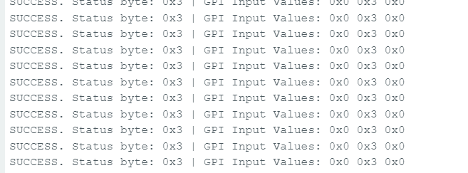
Serial.println("XVF3800 GPI Read Test Starting...");
}
void loop() {
uint8_t gpi_values[GPI_READ_NUM_BYTES] = {0};
uint8_t status = 0xFF;
bool success = read_gpi_values(gpi_values, &status);
if (success) {
Serial.print("I2C Communication SUCCESS. Status byte: 0x");
Serial.print(status, HEX);
Serial.print(" | GPI Input Values: ");
for (uint8_t i = 0; i < GPI_READ_NUM_BYTES; i++) {
Serial.print("0x");
Serial.print(gpi_values[i], HEX);
Serial.print(" ");
}
Serial.println();
} else {
Serial.println("Failed to read GPI values.");
}
delay(1000);
}
bool read_gpi_values(uint8_t *buffer, uint8_t *status) {
const uint8_t resid = IO_CONFIG_SERVICER_RESID;
const uint8_t cmd = IO_CONFIG_SERVICER_RESID_GPI_READ_VALUES | 0x80; // Read command
const uint8_t read_len = GPI_READ_NUM_BYTES;
// Step 1: Send the command
Wire.beginTransmission(XMOS_ADDR);
Wire.write(resid);
Wire.write(cmd);
Wire.write(read_len + 1); // +1 for status byte
uint8_t result = Wire.endTransmission();
if (result != 0) {
Serial.print("I2C Write Error: ");
Serial.println(result);
return false;
}
// Step 2: Read response (status + payload)
Wire.requestFrom(XMOS_ADDR, (uint8_t)(read_len + 1));
if (Wire.available() < read_len + 1) {
Serial.println("I2C Read Error: Not enough data received.");
return false;
}
*status = Wire.read(); // first byte is status
for (uint8_t i = 0; i < read_len; i++) {
buffer[i] = Wire.read();
}
return true;
}
Escrever no pino GPO – Exemplo de mute do microfone
Objetivo: Controlar um GPIO de saída, por exemplo, silenciar o microfone alternando o GPIO 30 (X0D30). Destaques do código:
- Envia um comando de escrita para:
- ID de recurso: 20
- ID de comando: 1 (GPO_WRITE_VALUE)
- Payload: número do pino, valor
e.g., {30, 1} to mute
Funções de conveniência:
- muteMic() → define o GPIO 30 como ALTO para silenciar o microfone e acender o LED vermelho
- unmuteMic() → define o GPIO 30 como BAIXO para reativar o microfone e apagar o LED
#include <Wire.h>

// Define the 7-bit I2C address of the XVF3800 device
#define XMOS_ADDR 0x2C

// Define XVF3800 Resource and Command IDs
#define GPO_SERVICER_RESID 20                         // Resource ID for GPIO Output (GPO)
#define GPO_SERVICER_RESID_GPO_WRITE_VALUE 1          // Command ID to write value to GPIO
#define IO_CONFIG_SERVICER_RESID 36                   // Resource ID for IO Configuration
#define IO_CONFIG_SERVICER_RESID_GPI_VALUE_ALL 6      // Command ID to read all GPIO input values

void setup() {
  Wire.begin();                 // Initialize I2C communication
  Serial.begin(115200);        // Initialize serial communication for debugging
  delay(1000);                 // Short delay to allow device startup

  Serial.println("Muting Mic (Setting GPIO 30 HIGH)");
  muteMic();                   // Set GPIO 30 HIGH to mute microphone
  delay(5000);                 // Wait for 5 seconds

  Serial.println("Unmuting Mic (Setting GPIO 30 LOW)");
  unmuteMic();                 // Set GPIO 30 LOW to unmute microphone
  delay(3000);                 // Wait for 3 seconds

  Serial.println("Reading GPIO Status...");
  readGPIOStatus();            // Read and print the status of all GPIOs
}

void loop() {
  // Empty loop - no repeated actions for now
}

// Function to set GPIO 30 to a specific logic level (0 = LOW, 1 = HIGH)
void setGPIO30(uint8_t level) {
  uint8_t payload[2] = {30, level};  // Payload format: [GPIO index, value]
  xmos_write_bytes(GPO_SERVICER_RESID, GPO_SERVICER_RESID_GPO_WRITE_VALUE, payload, 2);

  Serial.print("Command Sent: GPIO 30 = ");
  Serial.println(level);
}

// Convenience function to mute the microphone (set GPIO 30 HIGH)
void muteMic() {
  setGPIO30(1);  // Logic HIGH to mute
}

// Convenience function to unmute the microphone (set GPIO 30 LOW)
void unmuteMic() {
  setGPIO30(0);  // Logic LOW to unmute
}

// Function to write a sequence of bytes over I2C to the XVF3800
void xmos_write_bytes(uint8_t resid, uint8_t cmd, uint8_t *value, uint8_t write_byte_num) {
  Wire.beginTransmission(XMOS_ADDR); // Begin I2C transmission to XVF3800
  Wire.write(resid);                 // Write the resource ID
  Wire.write(cmd);                   // Write the command ID
  Wire.write(write_byte_num);       // Write number of payload bytes
  for (uint8_t i = 0; i < write_byte_num; i++) {
    Wire.write(value[i]);           // Write each payload byte
  }
  Wire.endTransmission();           // End the I2C transmission
}

// Function to read the status of all GPIO inputs (32 bits) from XVF3800
void readGPIOStatus() {
  uint8_t buffer[4] = {0};  // Buffer to hold the 4-byte GPIO status response

  // --- Write phase: Send read request ---
  Wire.beginTransmission(XMOS_ADDR);                        // Begin I2C write transaction
  Wire.write(IO_CONFIG_SERVICER_RESID);                     // Write the resource ID for IO config
  Wire.write(IO_CONFIG_SERVICER_RESID_GPI_VALUE_ALL);       // Write the command ID to get all GPIO values
  Wire.write(1);                                             // Payload length (1 byte)
  Wire.endTransmission(false);                              // End transmission with repeated start (no stop)

  // --- Read phase: Read response from device ---
  Wire.requestFrom(XMOS_ADDR, 5); // Request 5 bytes: 1 status byte + 4 data bytes

  if (Wire.available() < 5) {
    Serial.println("Error: Not enough bytes received from XVF3800.");
    return;
  }

  uint8_t status = Wire.read();  // Read the status byte (should be 0 for success)

  // Read the 4-byte GPIO input status value
  for (int i = 0; i < 4; i++) {
    buffer[i] = Wire.read();
  }

  // Combine 4 bytes into a single 32-bit unsigned integer
  uint32_t gpio_status = ((uint32_t)buffer[3] << 24) |
                         ((uint32_t)buffer[2] << 16) |
                         ((uint32_t)buffer[1] << 8)  |
                         ((uint32_t)buffer[0]);

  Serial.print("GPIO Status Register = 0x");
  Serial.println(gpio_status, HEX);

  // Check and print the state of GPIO 30 specifically
  bool gpio30 = (gpio_status >> 30) & 0x01;
  Serial.print("GPIO 30 State: ");
  Serial.println(gpio30 ? "HIGH (Muted)" : "LOW (Unmuted)");
}
Suporte Técnico e Discussão sobre Produtos
Obrigado por escolher nossos produtos! Estamos aqui para fornecer diferentes formas de suporte e garantir que sua experiência com nossos produtos seja a mais tranquila possível. Oferecemos vários canais de comunicação para atender a diferentes preferências e necessidades.