Livro de Receitas Arduino: RTC, Baixo Consumo, Áudio e Toque (reTerminal E Series)
Se você quiser visualizar rapidamente os resultados do projeto ou testar o firmware demo básico antes de configurar um ambiente de desenvolvimento, abra o reTerminal E-Series Firmware Hub. Você pode escolher um dispositivo reTerminal E Series compatível e gravar o firmware de demonstração diretamente a partir de um navegador.
- Arduino Cookbook: ePaper Display — renderização de texto, gráficos e imagens na tela de ePaper.
- Arduino Cookbook: Onboard Peripherals — LED, buzzer, botões, sensor SHT4x, monitor de bateria, cartão microSD e o pipeline de imagens via cartão SD.
Introdução
Este é o segundo livro de receitas de periféricos para a reTerminal E Series. Enquanto o primeiro livro de receitas de periféricos cobre os periféricos básicos de E/S (LED, buzzer, botões, SHT4x, bateria, cartão SD), esta página aprofunda em quatro tópicos mais avançados:
- Relógio de Tempo Real (RTC) — o chip RTC PCF8563 onboard, alimentado por uma bateria tipo moeda CR1220, que mantém a hora mesmo quando a bateria principal é removida.
- Modos de Baixo Consumo — deep sleep, light sleep e estratégias de despertar por GPIO para estender a vida útil da bateria de dias para meses.
- Microfone PDM — captura de áudio através do microfone digital PDM onboard (apenas E1001 / E1002 / E1003; o E1004 não possui microfone) e salvamento de arquivos WAV no cartão microSD.
- Tela sensível ao toque — uso do painel de toque capacitivo onboard no E1003 (modelo de 10,3") para desenhar pontos na tela de ePaper. Apenas o E1003 possui painel de toque.
Todos os sketches de exemplo deste livro de receitas vêm do repositório OSHW-reTerminal-Series-E-D. Os sketches de RTC, baixo consumo e microfone não exigem instalação adicional de bibliotecas — tudo usa as APIs internas do ESP32. O sketch de toque requer a biblioteca Seeed_GFX.
Materiais Necessários
Este livro de receitas se aplica à reTerminal E Series. Escolha o dispositivo que você tiver em mãos:
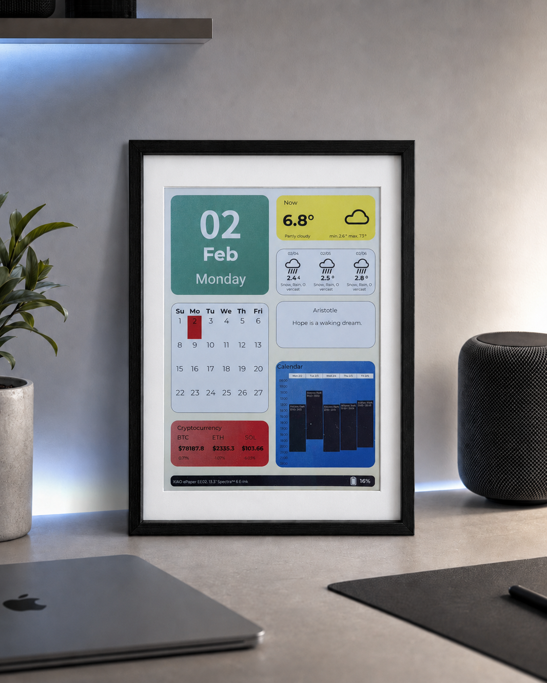
| reTerminal E1001 | reTerminal E1002 | reTerminal E1003 | reTerminal E1004 |
|---|---|---|---|
 |  | 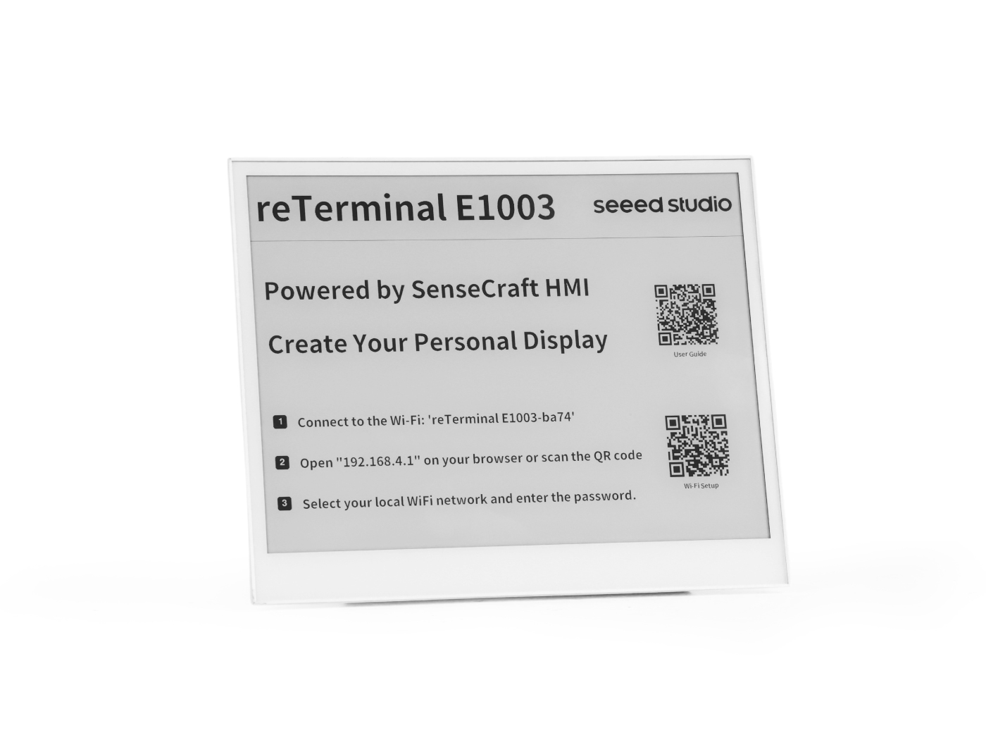 |  |
Pré-requisitos
Antes de executar qualquer exemplo abaixo, você já deve ter:
- A IDE Arduino instalada com o pacote de placas ESP32 (≥ 3.0 para o microfone PDM) e a placa XIAO_ESP32S3 selecionada.
- PSRAM configurada como OPI PSRAM e Flash configurada como 8 MB no menu Tools.
- Um cabo de dados USB-C funcional e a porta serial correta selecionada.
- Verificado que você consegue gravar um sketch básico no dispositivo — veja a preparação do ambiente em Arduino Cookbook: ePaper Display se ainda não tiver feito isso.
Todos os sketches deste livro de receitas imprimem informações de depuração através de Serial1 nos pinos GPIO44 (RX) / GPIO43 (TX) a 115200 baud — esta é a ponte USB-UART de transporte, não o Serial USB-CDC que a IDE Arduino abre automaticamente. Abra o Monitor Serial da Arduino IDE e selecione a porta e taxa de baud correspondentes para acompanhar.
Visão Geral da Compatibilidade de Hardware
Nem todos os recursos deste livro de receitas estão disponíveis em todos os quatro modelos. A tabela abaixo resume o que você pode usar:
| Recurso | E1001 | E1002 | E1003 | E1004 |
|---|---|---|---|---|
| PCF8563 RTC (externo, I2C 0x51, backup com CR1220) | ✅ | ✅ | ✅ | ✅ |
| Deep sleep / light sleep | ✅ | ✅ | ✅ | ✅ |
| Despertar por botão (KEY0) | ✅ | ✅ | ✅ | ✅ |
| Gravação com microfone PDM | ✅ | ✅ | ✅ | ❌ |
| Painel de toque capacitivo | ❌ | ❌ | ✅ | ❌ |
Relógio de Tempo Real (RTC)
Todo modelo da reTerminal E Series inclui um chip de relógio de tempo real PCF8563 da NXP, com seu próprio cristal de 32,768 kHz e um suporte para bateria tipo moeda CR1220 que mantém o tempo correndo mesmo quando a bateria principal é removida ou totalmente descarregada.
A bateria tipo moeda CR1220 não é enviada com o dispositivo. Você precisa comprar uma bateria CR1220 separadamente e instalá-la antes que o RTC possa manter a hora entre ciclos de energia.
Instalando a Bateria CR1220
O suporte da bateria CR1220 está localizado na parte de trás da PCB. As etapas de desmontagem diferem ligeiramente entre os modelos:
- E1001 / E1002
- E1003
- E1004
Passo 1 — Desligue o dispositivo
Desconecte o cabo USB-C e certifique-se de que o dispositivo esteja completamente desligado.
Passo 2 — Remova a tampa traseira
Remova os quatro parafusos no painel traseiro e retire a tampa de trás para expor a PCB.
Passo 3 — Localize o suporte da bateria
Encontre o suporte da bateria tipo moeda CR1220 na PCB (marcado como BT2 ou CR1220).
Passo 4 — Insira a bateria
Coloque a bateria CR1220 no suporte com o lado positivo (+) voltado para cima. Pressione suavemente até que ela se encaixe no lugar.
Passo 5 — Refaça a montagem
Recoloque a tampa traseira e aperte os quatro parafusos. O RTC agora é alimentado pela bateria e manterá a hora mesmo quando a alimentação principal estiver desconectada.
Passo 1 — Desligue o dispositivo
Desconecte o cabo USB-C e certifique-se de que o dispositivo esteja completamente desligado.
Passo 2 — Remova a tampa traseira
Remova os parafusos do painel traseiro e retire a tampa traseira para expor a placa de circuito impresso (PCB).
Passo 3 — Localize o suporte da bateria
Encontre o suporte para bateria tipo moeda CR1220 na PCB (marcado como BT2 ou CR1220).
Passo 4 — Insira a bateria
Coloque a bateria CR1220 no suporte com o lado positivo (+) voltado para cima. Pressione suavemente até que ela se encaixe no lugar.
Passo 5 — Refaça a montagem
Recoloque a tampa traseira e aperte os parafusos. O RTC agora é alimentado pela bateria e manterá a hora mesmo quando a alimentação principal estiver desconectada.
Passo 1 — Desligue o dispositivo
Desconecte o cabo USB-C e certifique-se de que o dispositivo esteja completamente desligado.
Passo 2 — Remova a tampa traseira
Remova os parafusos ao redor do perímetro do painel traseiro e retire cuidadosamente a tampa traseira para expor a placa de circuito impresso (PCB).
Passo 3 — Localize o suporte da bateria
Encontre o suporte para bateria tipo moeda CR1220 na PCB (marcado como BT2 ou CR1220).
Passo 4 — Insira a bateria
Coloque a bateria CR1220 no suporte com o lado positivo (+) voltado para cima. Pressione suavemente até que ela se encaixe no lugar.
Passo 5 — Refaça a montagem
Recoloque a tampa traseira e aperte todos os parafusos. O RTC agora é alimentado pela bateria e manterá a hora mesmo quando a alimentação principal estiver desconectada.
Visão geral do hardware
| Parâmetro | Valor |
|---|---|
| Chip | PCF8563M/TR (NXP) |
| Barramento | I2C — endereço 0x51 (fixo no silício) |
| SCL | GPIO20 |
| SDA | GPIO19 |
| Cristal | 32,768 kHz (pinos OSCI / OSCO) |
| Bateria de backup | Bateria tipo moeda CR1220 — mantém a hora quando a alimentação principal é removida |
| Sinalizador VL | Definido pelo chip quando a tensão da bateria de backup está muito baixa; indica que a hora é pouco confiável |
Sketch completo: RTC_PCF8563
O sketch completo está disponível no repositório: examples/RTC_PCF8563/RTC_PCF8563.ino.
Clique para expandir o código completo de RTC_PCF8563.ino
// ============================================================
// USER CONFIGURATION
// ============================================================

// --- How to set the initial time ---
//
// OPTION A — Compile-time (recommended):
//   Uncomment USE_COMPILE_TIME.  The C compiler embeds __DATE__ / __TIME__
//   (the exact moment you clicked "Upload") into the binary automatically.
//   No need to type the date by hand — just compile and flash.
//
#define USE_COMPILE_TIME
//
// OPTION B — Manual:
//   Comment out USE_COMPILE_TIME above, then fill in the values below.
//   INITIAL_YEAR must be in the range 2000–2099.
#define INITIAL_YEAR   2026
#define INITIAL_MONTH     5   // 1–12
#define INITIAL_DAY      26   // 1–31
#define INITIAL_HOUR     14   // 0–23
#define INITIAL_MIN       0   // 0–59
#define INITIAL_SEC       0   // 0–59

// --- When to write the time ---
//
// You do NOT need to touch anything here for normal use.
//
// How it works automatically:
//   • New board / battery just replaced → PCF8563 sets VL=1 internally
//     → code detects VL=1 at boot → writes the initial time once → done.
//   • Every reboot after that (battery healthy, VL=0)
//     → stored time is kept, nothing is overwritten.
//
// FORCE_SET_TIME is only for manual re-calibration (e.g. correcting drift).
// If you uncomment it, the clock is overwritten on EVERY boot — make sure
// to comment it out again and re-flash right after calibrating.
//
// #define FORCE_SET_TIME

// ============================================================
// END OF USER CONFIGURATION — no need to edit below this line
// ============================================================

#include <Wire.h>
#include <time.h>
#include <sys/time.h>

// ============================================================
// RtcTime — carries all date/time fields returned by rtcGetTime().
//
// Defined here, right after the #includes, so that Arduino IDE's
// automatic function-prototype injection (which is inserted after
// the last #include) can see the type before using it in prototypes
// like  static bool rtcGetTime(RtcTime &rt).
// ============================================================
struct RtcTime {
    int  year;       // full year (e.g. 2026)
    int  month;      // 1–12
    int  day;        // 1–31
    int  weekday;    // 0=Sunday … 6=Saturday
    int  hour;       // 0–23
    int  minute;     // 0–59
    int  second;     // 0–59
    bool voltageOK;  // false → VL flag set, battery was drained, time unreliable
};

// ---------- Serial debug (carrier USB-UART bridge) ----------
#define PIN_SERIAL_RX   44
#define PIN_SERIAL_TX   43
#define LOG             Serial1

// ---------- I2C pins (identical on all E1001 / E1002 / E1003 / E1004) --------
#define PIN_I2C_SCL     20   // ESP_IO20 / I2C0_SCL
#define PIN_I2C_SDA     19   // ESP_IO19 / I2C0_SDA

// ---------- PCF8563 I2C address (7-bit, fixed in hardware) -------------------
#define PCF8563_ADDR    0x51

// ---------- PCF8563 register map (only the registers used here) --------------
#define REG_CTRL1       0x00   // Control/Status 1 — bit5 STOP halts the clock
#define REG_CTRL2       0x01   // Control/Status 2
#define REG_SECONDS     0x02   // bit7 = VL (voltage-low flag); bits6:0 = seconds
#define REG_MINUTES     0x03   // bits6:0 = minutes
#define REG_HOURS       0x04   // bits5:0 = hours
#define REG_DAYS        0x05   // bits5:0 = day-of-month
#define REG_WEEKDAYS    0x06   // bits2:0 = weekday (0=Sunday)
#define REG_MONTHS      0x07   // bit7 = century (0→2000s, 1→1900s); bits4:0 = month
#define REG_YEARS       0x08   // bits7:0 = year within century (BCD, 00–99)
#define REG_CLKOUT      0x0D   // CLKOUT control — bit7 FE enables clock output pin

// ============================================================
// BCD ↔ decimal conversion
// The PCF8563 stores all time fields in BCD (Binary-Coded Decimal):
//   e.g. decimal 26 → upper nibble=2, lower nibble=6 → 0x26
// ============================================================
static inline uint8_t bcdToDec(uint8_t bcd)
{
    return static_cast<uint8_t>(((bcd >> 4) * 10U) + (bcd & 0x0FU));
}

static inline uint8_t decToBcd(uint8_t dec)
{
    return static_cast<uint8_t>(((dec / 10U) << 4) | (dec % 10U));
}

// ============================================================
// I2C read / write helpers
// ============================================================

// Read `len` consecutive registers starting at `reg` into `buf`.
// Uses a repeated-START (no STOP between write and read) as required by the
// PCF8563 data sheet.
static bool rtcReadRegs(uint8_t reg, uint8_t *buf, size_t len)
{
    Wire.beginTransmission(PCF8563_ADDR);
    Wire.write(reg);
    if (Wire.endTransmission(false) != 0) return false;   // repeated START

    const uint8_t received = Wire.requestFrom(static_cast<uint8_t>(PCF8563_ADDR),
                                              static_cast<uint8_t>(len));
    if (received != len) return false;

    for (size_t i = 0; i < len; i++) {
        buf[i] = static_cast<uint8_t>(Wire.read());
    }
    return true;
}

// Write a single register.
static bool rtcWriteReg(uint8_t reg, uint8_t value)
{
    Wire.beginTransmission(PCF8563_ADDR);
    Wire.write(reg);
    Wire.write(value);
    return Wire.endTransmission() == 0;
}

// ============================================================
// PCF8563 API
// ============================================================

// Check whether the chip responds on the I2C bus.
static bool rtcProbe()
{
    Wire.beginTransmission(PCF8563_ADDR);
    return Wire.endTransmission() == 0;
}

// Clear the STOP bit so the oscillator runs, and disable the CLKOUT pin
// (saves a small amount of power when the clock output is not needed).
static bool rtcInit()
{
    if (!rtcWriteReg(REG_CTRL1, 0x00)) return false;   // STOP=0 → run
    if (!rtcWriteReg(REG_CTRL2, 0x00)) return false;   // clear alarm/timer flags
    if (!rtcWriteReg(REG_CLKOUT, 0x00)) return false;  // FE=0 → disable CLKOUT
    return true;
}

// Return false if the voltage-low flag is set (time data is unreliable).
static bool rtcVoltageOK()
{
    uint8_t sec = 0;
    if (!rtcReadRegs(REG_SECONDS, &sec, 1)) return false;
    return (sec & 0x80U) == 0U;   // VL bit = 0 means voltage has been OK
}

// Write date and time to the RTC.
// `year` must be in the range 2000–2099.
// Weekday is computed automatically from the supplied date.
static bool rtcSetTime(int year, int month, int day,
                       int hour, int minute, int second)
{
    if (year  < 2000 || year  > 2099) return false;
    if (month < 1    || month > 12  ) return false;
    if (day   < 1    || day   > 31  ) return false;
    if (hour  < 0    || hour  > 23  ) return false;
    if (minute < 0   || minute > 59 ) return false;
    if (second < 0   || second > 59 ) return false;

    // Use mktime() to derive the weekday (0=Sunday) from the calendar date.
    struct tm t = {};
    t.tm_year = year - 1900;
    t.tm_mon  = month - 1;
    t.tm_mday = day;
    mktime(&t);   // fills t.tm_wday

    // Write all 7 time registers in one burst starting at REG_SECONDS.
    // The PCF8563 auto-increments the internal address pointer after each byte.
    Wire.beginTransmission(PCF8563_ADDR);
    Wire.write(REG_SECONDS);
    Wire.write(decToBcd(static_cast<uint8_t>(second)));
    Wire.write(decToBcd(static_cast<uint8_t>(minute)));
    Wire.write(decToBcd(static_cast<uint8_t>(hour)));
    Wire.write(decToBcd(static_cast<uint8_t>(day)));
    Wire.write(static_cast<uint8_t>(t.tm_wday));         // weekday is not BCD
    Wire.write(decToBcd(static_cast<uint8_t>(month)));   // century bit = 0 → 2000s
    Wire.write(decToBcd(static_cast<uint8_t>(year % 100)));
    return Wire.endTransmission() == 0;
}

// Read the current date and time from the RTC into an RtcTime struct.
static bool rtcGetTime(RtcTime &rt)
{
    uint8_t raw[7] = {};
    // Burst-read 7 bytes: seconds, minutes, hours, days, weekdays, months, years
    if (!rtcReadRegs(REG_SECONDS, raw, 7)) return false;

    rt.voltageOK = (raw[0] & 0x80U) == 0U;                // VL flag
    rt.second    = bcdToDec(raw[0] & 0x7FU);
    rt.minute    = bcdToDec(raw[1] & 0x7FU);
    rt.hour      = bcdToDec(raw[2] & 0x3FU);
    rt.day       = bcdToDec(raw[3] & 0x3FU);
    rt.weekday   = bcdToDec(raw[4] & 0x07U);
    rt.month     = bcdToDec(raw[5] & 0x1FU);

    const int yr = bcdToDec(raw[6]);
    // Century bit 1 in REG_MONTHS → 1900s, bit 0 → 2000s
    rt.year      = ((raw[5] & 0x80U) != 0U) ? (1900 + yr) : (2000 + yr);

    return true;
}

// ============================================================
// Sync the ESP32's POSIX system clock from the RTC.
// After calling this, standard C functions like time(), localtime(),
// and strftime() will return the correct time.
// ============================================================
static void syncSystemClock(const RtcTime &rt)
{
    struct tm t = {};
    t.tm_year = rt.year - 1900;
    t.tm_mon  = rt.month - 1;
    t.tm_mday = rt.day;
    t.tm_hour = rt.hour;
    t.tm_min  = rt.minute;
    t.tm_sec  = rt.second;
    const time_t epoch = mktime(&t);
    struct timeval tv  = { epoch, 0 };
    settimeofday(&tv, nullptr);
}

// ============================================================
// Compile-time timestamp parser
//
// The C preprocessor provides two string literals in every translation unit:
//   __DATE__  →  "May 26 2026"  (month name, day, 4-digit year)
//   __TIME__  →  "14:53:00"    (HH:MM:SS, 24-hour)
//
// We parse them here so callers get plain integers without any library.
// ============================================================
#ifdef USE_COMPILE_TIME
static void getCompileTime(int &year, int &month, int &day,
                           int &hour, int &minute, int &second)
{
    // Map the 3-letter month abbreviation to 1–12.
    // strncmp compares only the first 3 characters, so this is safe.
    const char *abbr  = __DATE__;       // "May 26 2026"
    const char *names = "JanFebMarAprMayJunJulAugSepOctNovDec";
    month = 1;
    for (int i = 0; i < 12; i++) {
        if (strncmp(abbr, names + i * 3, 3) == 0) { month = i + 1; break; }
    }

    // __DATE__ + 4  →  "26 2026"  (day starts at offset 4)
    // __DATE__ + 7  →  "2026"     (year starts at offset 7)
    day  = atoi(__DATE__ + 4);
    year = atoi(__DATE__ + 7);

    // __TIME__      →  "14:53:00"
    // __TIME__ + 3  →  "53:00"
    // __TIME__ + 6  →  "00"
    hour   = atoi(__TIME__);
    minute = atoi(__TIME__ + 3);
    second = atoi(__TIME__ + 6);
}
#endif  // USE_COMPILE_TIME

// ============================================================
// Helpers
// ============================================================
static const char *kWeekdayNames[] = {
    "Sun", "Mon", "Tue", "Wed", "Thu", "Fri", "Sat"
};

// ============================================================
// Global state
// ============================================================
static unsigned long s_lastPrintMs = 0;

// ============================================================
// setup()
// ============================================================
void setup()
{
    // Use Serial1 (the USB-UART bridge on the carrier board, not USB-CDC).
    // GPIO43 = TX, GPIO44 = RX of the bridge chip.
    LOG.begin(115200, SERIAL_8N1, PIN_SERIAL_RX, PIN_SERIAL_TX);
    delay(500);

    LOG.println("=========================================");
    LOG.println("  RTC_PCF8563 — reTerminal E Series");
    LOG.println("=========================================");

    // ── Step 1: initialise I2C at 400 kHz (PCF8563 supports up to 400 kHz) ──
    Wire.begin(PIN_I2C_SDA, PIN_I2C_SCL);
    Wire.setClock(400000UL);
    LOG.printf("[I2C] Bus started: SDA=GPIO%d  SCL=GPIO%d  400 kHz\n",
               PIN_I2C_SDA, PIN_I2C_SCL);

    // ── Step 2: check the PCF8563 is reachable ──
    LOG.printf("[RTC] Probing PCF8563 at I2C address 0x%02X ...", PCF8563_ADDR);
    if (!rtcProbe()) {
        LOG.println(" NOT FOUND");
        LOG.println("[RTC] FATAL: check wiring and backup battery. Halting.");
        while (true) delay(1000);
    }
    LOG.println(" OK");

    // ── Step 3: clear STOP bit, disable CLKOUT ──
    if (!rtcInit()) {
        LOG.println("[RTC] FATAL: could not initialise PCF8563. Halting.");
        while (true) delay(1000);
    }

    // ── Step 4: decide whether the time needs to be set ──
    //
    // The VL (voltage-low) flag is stored inside the PCF8563 and survives
    // power cycles.  It is set by the chip whenever the backup battery
    // voltage has been too low to keep the clock running reliably.
    // We treat a set VL flag as "time is unknown and must be initialised".
    const bool voltageWasLow = !rtcVoltageOK();

#ifdef FORCE_SET_TIME
    const bool doSetTime = true;
    LOG.println("[RTC] FORCE_SET_TIME defined — overwriting RTC time.");
#else
    const bool doSetTime = voltageWasLow;
    if (voltageWasLow) {
        LOG.println("[RTC] WARNING: VL flag set — backup battery may be depleted.");
        LOG.println("[RTC] Time is unreliable; resetting to INITIAL_* constants.");
    } else {
        LOG.println("[RTC] Battery OK — retaining stored time.");
    }
#endif

    if (doSetTime) {
#ifdef USE_COMPILE_TIME
        // Parse the timestamp baked in at compile time.
        // __DATE__ / __TIME__ are evaluated by the C preprocessor during
        // compilation, so they reflect the moment "Upload" was clicked.
        int cy, cm, cd, ch, cmin, cs;
        getCompileTime(cy, cm, cd, ch, cmin, cs);
        LOG.printf("[RTC] Setting time from compile timestamp: "
                   "%04d-%02d-%02d  %02d:%02d:%02d\n",
                   cy, cm, cd, ch, cmin, cs);
        if (!rtcSetTime(cy, cm, cd, ch, cmin, cs)) {
            LOG.println("[RTC] ERROR: rtcSetTime() failed.");
        }
#else
        LOG.printf("[RTC] Setting time from INITIAL_* constants: "
                   "%04d-%02d-%02d  %02d:%02d:%02d\n",
                   INITIAL_YEAR, INITIAL_MONTH, INITIAL_DAY,
                   INITIAL_HOUR, INITIAL_MIN,   INITIAL_SEC);
        if (!rtcSetTime(INITIAL_YEAR, INITIAL_MONTH, INITIAL_DAY,
                        INITIAL_HOUR, INITIAL_MIN,   INITIAL_SEC)) {
            LOG.println("[RTC] ERROR: rtcSetTime() failed.");
        }
#endif
    }

    // ── Step 5: read back and sync the ESP32 system clock ──
    //
    // The ESP32 has its own software RTC that resets to Jan 1 1970 on each
    // power cycle.  By calling settimeofday() once at boot, we keep the
    // ESP32's POSIX time() / localtime() / strftime() in sync with the
    // hardware RTC so the rest of the firmware can use standard C time APIs.
    RtcTime rt;
    if (rtcGetTime(rt)) {
        syncSystemClock(rt);
        LOG.printf("[RTC] Current time: %04d-%02d-%02d (%s)  %02d:%02d:%02d\n",
                   rt.year, rt.month, rt.day, kWeekdayNames[rt.weekday],
                   rt.hour, rt.minute, rt.second);
        LOG.println("[RTC] ESP32 system clock synced.");
    } else {
        LOG.println("[RTC] ERROR: could not read time after init.");
    }

    LOG.println();
    LOG.println("[READY] Printing time every second.");
}

// ============================================================
// loop()
// ============================================================
void loop()
{
    const unsigned long now = millis();

    // Print time once per second (non-blocking: compare elapsed time instead
    // of calling delay(), so other tasks in loop() are never blocked).
    if (now - s_lastPrintMs >= 1000UL) {
        s_lastPrintMs = now;

        RtcTime rt;
        if (rtcGetTime(rt)) {
            // Show the time read directly from the hardware RTC.
            // The "[VL]" tag warns that the chip saw a low-voltage event.
            LOG.printf("[TIME] %04d-%02d-%02d (%s)  %02d:%02d:%02d%s\n",
                       rt.year, rt.month, rt.day,
                       kWeekdayNames[rt.weekday],
                       rt.hour, rt.minute, rt.second,
                       rt.voltageOK ? "" : "  [VL: battery low!]");

            // ── Optional: also print the time via the ESP32 POSIX API ──
            // This demonstrates that the system clock (synced at boot) is
            // ticking independently of the I2C bus.
            char buf[32];
            time_t epoch = time(nullptr);
            struct tm info;
            localtime_r(&epoch, &info);
            strftime(buf, sizeof(buf), "%Y-%m-%d %H:%M:%S", &info);
            LOG.printf("[SYS ] ESP32 system time: %s\n", buf);

        } else {
            LOG.println("[RTC] ERROR: rtcGetTime() failed — check I2C bus.");
        }
    }
}
Como o código funciona
O código segue uma sequência de inicialização em 5 etapas em setup():
- Inicializar o barramento I2C a 400 kHz nos GPIO19 (SDA) / GPIO20 (SCL) — os pinos I2C padrão do reTerminal compartilhados com o sensor SHT4x.
- Sondar o PCF8563 no endereço 0x51 para verificar se o chip está respondendo.
- Inicializar o chip — limpar o bit STOP (para que o oscilador funcione), limpar os flags de alarme e desabilitar o pino CLKOUT para economizar energia.
- Decidir se deve ajustar a hora — o PCF8563 possui um flag VL (Voltage Low) que é definido automaticamente quando a tensão da bateria de backup cai demais. Se VL estiver definido (primeira inicialização ou bateria substituída), o código grava a hora inicial; caso contrário, mantém a hora armazenada.
- Sincronizar o relógio de sistema do ESP32 — após ler a hora do PCF8563,
settimeofday()é chamado para que as funções de tempo padrão em C (time(),localtime(),strftime()) retornem a hora correta no restante do firmware.
O loop() lê o RTC uma vez por segundo via I2C e imprime a hora formatada. A tag [VL] aparece se a tensão da bateria de backup estiver baixa.
Opções de ajuste de hora
| Opção | Como ativar | Comportamento |
|---|---|---|
| Em tempo de compilação (recomendado) | #define USE_COMPILE_TIME | O pré-processador C incorpora __DATE__ / __TIME__ (o momento em que você clicou em Upload). Zero esforço — basta compilar e gravar. |
| Manual | Comente USE_COMPILE_TIME, preencha as constantes INITIAL_* | Você digita a data e hora exatas. Útil para ambientes offline. |
| Forçar sobrescrita | #define FORCE_SET_TIME | Sobrescreve o RTC em toda inicialização. Use para recalibração, depois comente e grave novamente. |
O flag VL é persistente entre ciclos de energia. Depois que a hora é ajustada e a bateria CR1220 está em boas condições, o PCF8563 continua contando e reinicializações subsequentes não a sobrescrevem.
Saída esperada
=========================================
  RTC_PCF8563 — reTerminal E Series
=========================================
[RTC] 2026-05-27 (Wed) 14:53:00
[READY] Printing time every second.
[TIME] 2026-05-27 (Wed) 14:53:01
[TIME] 2026-05-27 (Wed) 14:53:02
[TIME] 2026-05-27 (Wed) 14:53:03
Se a bateria de backup estiver esgotada ou ausente, você verá o aviso [VL: battery low!]:
[RTC] WARNING: VL flag set — backup battery may be depleted.
[TIME] 2026-05-27 (Wed) 14:53:01  [VL: battery low!]
Modos de baixo consumo
O ESP32-S3 oferece vários estados de energia. Os dois mais úteis para aplicações de ePaper alimentadas por bateria são deep sleep e light sleep:
| Estado de energia | CPU | Wi-Fi / BT | RAM | RTC | Fonte de despertar |
|---|---|---|---|---|---|
| Ativo | Em execução | Ligado | Toda | Ligado | — |
| Light Sleep | Pausado | Desligado | Retida | Ligado | GPIO, Timer |
| Deep Sleep | Desligado | Desligado | Perdida (exceto RTC) | Ligado | GPIO, Timer, Touch |
Sketch completo: LowPower_DeepSleep
O sketch completo está disponível no repositório: examples/LowPower_DeepSleep/LowPower_DeepSleep.ino.
Clique para expandir todo o código LowPower_DeepSleep.ino
// ============================================================
// USER CONFIGURATION
// ============================================================

// How many seconds to stay awake before entering deep sleep.
#define SLEEP_DELAY_SEC   5

// --- Wake-up button pin ---
// Uncomment the ONE line that matches your device.
// Only GPIO0–GPIO21 can wake the ESP32-S3 from deep sleep.
//
#define PIN_WAKE_BTN   3   // E1001 / E1002 / E1003 — KEY0
// #define PIN_WAKE_BTN   4   // E1004               — KEY0

// ============================================================
// END OF USER CONFIGURATION
// ============================================================

#include "esp_sleep.h"
#include "driver/rtc_io.h"

#define PIN_SERIAL_RX   44
#define PIN_SERIAL_TX   43
#define LOG             Serial1

// Survives deep sleep — increments on every wakeup.
RTC_DATA_ATTR static int s_bootCount = 0;

static const char* wakeupReason()
{
    switch (esp_sleep_get_wakeup_cause()) {
        case ESP_SLEEP_WAKEUP_EXT1:  return "GPIO button (EXT1)";
        default:                     return "power-on / manual reset";
    }
}

void setup()
{
    s_bootCount++;

    LOG.begin(115200, SERIAL_8N1, PIN_SERIAL_RX, PIN_SERIAL_TX);
    delay(100);

    LOG.println("========================================");
    LOG.println("  LowPower_DeepSleep — reTerminal E");
    LOG.println("========================================");
    LOG.printf("[WAKE] Boot #%d — wakeup: %s\n", s_bootCount, wakeupReason());
    LOG.printf("[WAKE] Entering deep sleep in %d seconds...\n", SLEEP_DELAY_SEC);
    LOG.printf("[WAKE] Press GPIO%d button to wake up.\n", PIN_WAKE_BTN);

    delay((uint32_t)SLEEP_DELAY_SEC * 1000);

    esp_sleep_enable_ext1_wakeup(1ULL << PIN_WAKE_BTN, ESP_EXT1_WAKEUP_ANY_LOW);

    // Normal GPIO pull-up is off during deep sleep; use keep-alive domain instead.
    rtc_gpio_pullup_en(static_cast<gpio_num_t>(PIN_WAKE_BTN));
    rtc_gpio_pulldown_dis(static_cast<gpio_num_t>(PIN_WAKE_BTN));

    LOG.println("[SLEEP] Entering deep sleep now.");
    LOG.flush();
    delay(10);

    esp_deep_sleep_start();
}

void loop()
{
    // esp_deep_sleep_start() in setup() never returns, so loop() is never reached.
    // If you see this message, deep sleep failed to start.
    LOG.println("[ERROR] deep sleep did not start!");
    delay(1000);
}
Como o código funciona
setup()inicia — incrementa o contador de inicializaçõesRTC_DATA_ATTR(essa variável é mantida no domínio de memória RTC do ESP32-S3, portanto sobrevive ao deep sleep).- Imprime o status — mostra a contagem de inicializações e por que o chip acordou (botão GPIO vs reset por energização).
- Aguarda
SLEEP_DELAY_SECsegundos (padrão 5) — isso lhe dá tempo para ler a saída serial. - Configura a fonte de despertar —
esp_sleep_enable_ext1_wakeup()registra o pino do botão (KEY0). O nível de despertar éLOWporque os botões são ativos em nível baixo com pull-ups de hardware. - Habilita o pull-up do RTC — os pull-ups GPIO normais são desabilitados durante o deep sleep.
rtc_gpio_pullup_en()usa o pull-up do domínio RTC para manter a linha do botão em nível ALTO enquanto estiver dormindo. - Entra em deep sleep —
esp_deep_sleep_start()desliga tudo, exceto o domínio RTC. A corrente cai para ~14 µA. - Ao pressionar o botão — o domínio RTC detecta a borda de descida no GPIO, o chip reinicia e
setup()é executado novamente a partir da etapa 1.
loop() contém uma instrução de impressão que nunca deve ser executada. Se você vir [ERROR] deep sleep did not start! no monitor serial, o deep sleep falhou. Silêncio após [SLEEP] significa que o dispositivo está realmente dormindo.
Seleção do pino de despertar por botão
O botão de despertar difere entre os modelos devido ao layout de GPIO:
| Modelo | Pino de despertar | PIN_WAKE_BTN | Observações |
|---|---|---|---|
| E1001 / E1002 / E1003 | GPIO3 (KEY0) | 3 | Botão do lado direito (Botão Verde no E1001/E1002) |
| E1004 | GPIO4 (KEY0) | 4 | Botão direcional direito (painel frontal) |
Descomente a linha correta na seção USER CONFIGURATION antes de gravar.
Saída esperada
Primeira inicialização (energização):
========================================
  LowPower_DeepSleep — reTerminal E
========================================
[WAKE] Boot #1 — wakeup: power-on / manual reset
[WAKE] Entering deep sleep in 5 seconds...
[WAKE] Press GPIO3 button to wake up.
[SLEEP] Entering deep sleep now.
Após pressionar KEY0 para acordar:
========================================
  LowPower_DeepSleep — reTerminal E
========================================
[WAKE] Boot #2 — wakeup: GPIO button (EXT1)
[WAKE] Entering deep sleep in 5 seconds...
[WAKE] Press GPIO3 button to wake up.
[SLEEP] Entering deep sleep now.
Padrão Acordar → Trabalhar → Dormir
Um padrão comum para aplicações com ePaper é:
- Acordar do deep sleep (timer ou botão).
- Ler o RTC para marcação de tempo.
- Ler sensores (SHT4x, bateria, etc.).
- Conectar ao Wi-Fi e buscar dados — se necessário.
- Atualizar o display ePaper com as novas informações.
- Voltar para deep sleep até o próximo despertar agendado.
Para adicionar um despertar por timer além do despertar por botão, basta adicionar:
esp_sleep_enable_timer_wakeup(30 * 60 * 1000000ULL); // 30 minutes
antes de chamar esp_deep_sleep_start(). Ambas as fontes de despertar podem estar ativas simultaneamente — a primeira que disparar vence.
Microfone (E1001 / E1002 / E1003)
O reTerminal E1004 não inclui um microfone onboard. Os exemplos desta seção se aplicam apenas a E1001, E1002 e E1003. Se você estiver usando um E1004, pule esta seção.
Os reTerminal E1001 / E1002 / E1003 incluem um microfone digital PDM (Pulse Density Modulation) onboard. Microfones PDM geram um fluxo sigma-delta de 1 bit que é decodificado pelo periférico PDM integrado do ESP32-S3 — nenhum codec externo é necessário.
Visão geral de hardware
| Sinal | Pino GPIO | Descrição |
|---|---|---|
| PDM_CLK | GPIO42 | Saída de clock para o microfone |
| PDM_DATA | GPIO41 | Entrada de dados de 1 bit do microfone |
| MIC_PWR_EN | GPIO38 | Habilitação de alimentação do microfone (ativo em nível ALTO) — deve ser acionado em nível ALTO antes do uso |
Os pinos são os mesmos nos E1001, E1002 e E1003. O pino de habilitação de alimentação do microfone (GPIO38) controla um chaveador de carga (TPS22916CYFPR) — você deve colocá-lo em nível ALTO antes de gravar e pode colocá-lo em nível BAIXO depois para economizar energia.
O sketch usa a API ESP-IDF 5.x PDM-RX (driver/i2s_pdm.h), que só está disponível na versão 3.0 ou superior do core Arduino ESP32. Certifique-se de que o pacote da sua placa esteja atualizado.
Sketch completo: MicRecordToSD
O sketch completo está disponível no repositório: examples/MicRecordToSD/MicRecordToSD.ino.
Clique para expandir o código completo de MicRecordToSD.ino
// ============================================================
// USER CONFIGURATION
// ============================================================

// Uncomment ONE line to select your hardware model:
// #define DEVICE_E1001_E1002   // reTerminal E1001 or E1002
#define DEVICE_E1003      // reTerminal E1003

// Recording parameters
#define SAMPLE_RATE      16000U  // Sample rate in Hz (8000 / 16000 / 44100)
#define MAX_RECORD_SECS  30      // Auto-stop after this many seconds (0 = unlimited)
#define RECORD_DIR       "/REC"  // Directory on the SD card root

// ============================================================
// END OF USER CONFIGURATION — no need to edit below this line
// ============================================================

#include <SD.h>
#include <SPI.h>
#include <driver/i2s_pdm.h>    // ESP-IDF 5.x PDM-RX API (Arduino ESP32 >= 3.0)
#include <driver/i2s_common.h>

// ---------- Serial debug ---------
#define PIN_SERIAL_RX   44
#define PIN_SERIAL_TX   43
#define LOG             Serial1

// ---------- PDM Microphone -------
// Same on E1001, E1002, and E1003.
#define PIN_MIC_CLK     42   // GPIO42 — PDM_CLK  (R109 in schematic)
#define PIN_MIC_DATA    41   // GPIO41 — PDM_DATA (R110 in schematic)
#define PIN_MIC_PWR_EN  38   // GPIO38 — MIC power enable (TPS22916CYFPR EN, ESP_IO3B)

// ---------- SD Card --------------
// SPI bus is shared with the ePaper display; a separate CS keeps them independent.
#define PIN_SD_DET       15  // Card detect (LOW = card present)
#define PIN_SD_CS        14  // SPI Chip Select
#define PIN_SD_MISO       8
#define PIN_SD_MOSI       9
#define PIN_SD_SCK        7

// ---------- User Button ----------
#define PIN_BTN_KEY0      3  // KEY0 — active LOW (hardware pull-up)

// ---------- Model-specific pins --
#if defined(DEVICE_E1001_E1002)
  #define PIN_SD_EN    16    // GPIO16 — SD card power enable
  #define PIN_LED       6    // GPIO6  — onboard LED (inverted: LOW = ON)
#elif defined(DEVICE_E1003)
  #define PIN_SD_EN    39    // GPIO39 — SD card power enable
  #define PIN_LED      16    // GPIO16 — onboard LED (inverted: LOW = ON)
#else
  #error "Please define DEVICE_E1001_E1002 or DEVICE_E1003 in the USER CONFIGURATION section."
#endif

// ---------- I2S / Audio ----------
#define I2S_PORT          I2S_NUM_0
#define DMA_BUF_COUNT     8     // number of DMA descriptors
#define DMA_BUF_LEN       512   // frames per DMA descriptor
#define BITS_PER_SAMPLE   16
#define AUDIO_CHANNELS    1
#define BYTES_PER_SAMPLE  (BITS_PER_SAMPLE / 8)
#define BYTES_PER_SEC     (SAMPLE_RATE * AUDIO_CHANNELS * BYTES_PER_SAMPLE)

// Single-read chunk: matches one DMA buffer (512 frames × 2 bytes = 1024 bytes)
#define READ_BUF_BYTES    (DMA_BUF_LEN * BYTES_PER_SAMPLE)
static uint8_t s_dmaBuf[READ_BUF_BYTES];

// ============================================================
// WAV file header (44 bytes, little-endian)
// ============================================================
#pragma pack(push, 1)
struct WavHeader {
    // RIFF chunk
    char     riffTag[4];      // "RIFF"
    uint32_t riffSize;        // file size − 8
    char     waveTag[4];      // "WAVE"
    // fmt sub-chunk
    char     fmtTag[4];       // "fmt "
    uint32_t fmtSize;         // 16 for PCM
    uint16_t audioFormat;     // 1 = PCM
    uint16_t numChannels;     // 1 = mono
    uint32_t sampleRate;
    uint32_t byteRate;        // sampleRate × channels × bytesPerSample
    uint16_t blockAlign;      // channels × bytesPerSample
    uint16_t bitsPerSample;
    // data sub-chunk
    char     dataTag[4];      // "data"
    uint32_t dataSize;        // audio payload in bytes
};
#pragma pack(pop)

static_assert(sizeof(WavHeader) == 44, "WavHeader must be 44 bytes");

// ============================================================
// Global state
// ============================================================
static i2s_chan_handle_t s_rxHandle    = nullptr;  // ESP-IDF 5.x channel handle
static SPIClass          s_spiSD(HSPI);
static File        s_wavFile;
static bool        s_recording     = false;
static uint32_t    s_recordedBytes = 0;
static uint32_t    s_fileIndex     = 1;

// Button debounce
static bool          s_lastRawBtn    = HIGH;
static bool          s_stableBtn     = HIGH;
static unsigned long s_debounceMs    = 0;
static const unsigned long DEBOUNCE_DELAY = 50;

// LED blink
static unsigned long s_lastBlinkMs  = 0;
static bool          s_ledState     = false;

// ============================================================
// LED helpers (inverted logic)
// ============================================================
static void ledOn()  { digitalWrite(PIN_LED, LOW);  }
static void ledOff() { digitalWrite(PIN_LED, HIGH); }

// ============================================================
// WAV helpers
// ============================================================
static void writeWavHeader(File& f, uint32_t dataBytes)
{
    WavHeader h;
    memcpy(h.riffTag,  "RIFF", 4);
    h.riffSize     = 36 + dataBytes;
    memcpy(h.waveTag,  "WAVE", 4);
    memcpy(h.fmtTag,   "fmt ", 4);
    h.fmtSize      = 16;
    h.audioFormat  = 1;
    h.numChannels  = AUDIO_CHANNELS;
    h.sampleRate   = SAMPLE_RATE;
    h.byteRate     = BYTES_PER_SEC;
    h.blockAlign   = AUDIO_CHANNELS * BYTES_PER_SAMPLE;
    h.bitsPerSample = BITS_PER_SAMPLE;
    memcpy(h.dataTag,  "data", 4);
    h.dataSize     = dataBytes;
    f.write(reinterpret_cast<const uint8_t*>(&h), sizeof(h));
}

// ============================================================
// SD card helpers
// ============================================================
static bool mountSD()
{
    pinMode(PIN_SD_EN, OUTPUT);
    digitalWrite(PIN_SD_EN, HIGH);
    delay(10);

    s_spiSD.end();
    s_spiSD.begin(PIN_SD_SCK, PIN_SD_MISO, PIN_SD_MOSI, PIN_SD_CS);

    if (!SD.begin(PIN_SD_CS, s_spiSD)) {
        LOG.println("[SD] Initialization failed — check card and formatting (FAT32).");
        return false;
    }
    LOG.printf("[SD] Mounted. Type: %s  Size: %llu MB\n",
               SD.cardType() == CARD_SDHC ? "SDHC" : "SD",
               SD.cardSize() / (1024ULL * 1024ULL));
    return true;
}

static String nextFilename()
{
    if (!SD.exists(RECORD_DIR)) {
        SD.mkdir(RECORD_DIR);
    }
    char buf[32];
    while (true) {
        snprintf(buf, sizeof(buf), "%s/REC_%04u.WAV", RECORD_DIR, s_fileIndex);
        if (!SD.exists(buf)) break;
        s_fileIndex++;
        if (s_fileIndex > 9999) s_fileIndex = 1;
    }
    return String(buf);
}

// ============================================================
// PDM / I2S helpers  (ESP-IDF 5.x new-API, Arduino ESP32 >= 3.0)
// ============================================================
static bool initMic()
{
    // ── Step 1: power up the microphone via the load switch ──
    LOG.println("[MIC] Powering on microphone...");
    pinMode(PIN_MIC_PWR_EN, OUTPUT);
    digitalWrite(PIN_MIC_PWR_EN, HIGH);
    delay(50);  // give the LDO and PDM decimation filter time to start up

    // ── Step 2: create an I2S RX channel ──
    LOG.println("[MIC] Creating I2S channel...");
    i2s_chan_config_t chanCfg = I2S_CHANNEL_DEFAULT_CONFIG(I2S_NUM_0, I2S_ROLE_MASTER);
    chanCfg.dma_desc_num  = DMA_BUF_COUNT;
    chanCfg.dma_frame_num = DMA_BUF_LEN;
    chanCfg.auto_clear    = true;

    esp_err_t err = i2s_new_channel(&chanCfg, nullptr, &s_rxHandle);
    if (err != ESP_OK) {
        LOG.printf("[MIC] i2s_new_channel failed: 0x%x\n", err);
        return false;
    }

    // ── Step 3: configure PDM-RX mode ──
    LOG.println("[MIC] Configuring PDM-RX mode...");
    i2s_pdm_rx_config_t pdmCfg = {};
    pdmCfg.clk_cfg  = I2S_PDM_RX_CLK_DEFAULT_CONFIG(SAMPLE_RATE);
    pdmCfg.slot_cfg = I2S_PDM_RX_SLOT_DEFAULT_CONFIG(I2S_DATA_BIT_WIDTH_16BIT,
                                                      I2S_SLOT_MODE_MONO);
    pdmCfg.gpio_cfg.clk             = static_cast<gpio_num_t>(PIN_MIC_CLK);
    pdmCfg.gpio_cfg.din             = static_cast<gpio_num_t>(PIN_MIC_DATA);
    pdmCfg.gpio_cfg.invert_flags.clk_inv = false;

    err = i2s_channel_init_pdm_rx_mode(s_rxHandle, &pdmCfg);
    if (err != ESP_OK) {
        LOG.printf("[MIC] i2s_channel_init_pdm_rx_mode failed: 0x%x\n", err);
        i2s_del_channel(s_rxHandle);
        s_rxHandle = nullptr;
        return false;
    }

    // ── Step 4: enable (starts the clock and DMA) ──
    LOG.println("[MIC] Enabling channel...");
    err = i2s_channel_enable(s_rxHandle);
    if (err != ESP_OK) {
        LOG.printf("[MIC] i2s_channel_enable failed: 0x%x\n", err);
        i2s_del_channel(s_rxHandle);
        s_rxHandle = nullptr;
        return false;
    }

    // ── Step 5: warm-up — discard a few DMA buffers with a finite timeout ──
    // The PDM decimation filter needs several milliseconds to settle.
    // Using a 500 ms timeout instead of portMAX_DELAY prevents hanging if
    // the hardware is not producing data for any reason.
    LOG.println("[MIC] Warming up PDM filter...");
    size_t dummy;
    for (int i = 0; i < 3; i++) {
        i2s_channel_read(s_rxHandle, s_dmaBuf, sizeof(s_dmaBuf),
                         &dummy, pdMS_TO_TICKS(500));
    }

    LOG.printf("[MIC] PDM initialized. Rate=%u Hz  Bits=%d  CLK=GPIO%d  DATA=GPIO%d\n",
               SAMPLE_RATE, BITS_PER_SAMPLE, PIN_MIC_CLK, PIN_MIC_DATA);
    return true;
}

// ============================================================
// Recording control
// ============================================================
static bool startRecording()
{
    String fname = nextFilename();
    s_wavFile = SD.open(fname, FILE_WRITE);
    if (!s_wavFile) {
        LOG.printf("[REC] Cannot create file: %s\n", fname.c_str());
        return false;
    }
    writeWavHeader(s_wavFile, 0);   // placeholder — filled in when recording stops
    s_recordedBytes = 0;
    s_recording     = true;
    ledOn();
    LOG.printf("[REC] Recording started → %s\n", fname.c_str());
    return true;
}

static void stopRecording()
{
    s_recording = false;
    ledOff();

    // Seek back to the beginning and rewrite the header with the real data size.
    s_wavFile.seek(0);
    writeWavHeader(s_wavFile, s_recordedBytes);
    s_wavFile.close();

    float seconds = static_cast<float>(s_recordedBytes) / BYTES_PER_SEC;
    LOG.printf("[REC] Recording stopped. %u bytes saved (%.1f s).\n",
               s_recordedBytes, seconds);
    s_fileIndex++;
}

// ============================================================
// setup()
// ============================================================
void setup()
{
    LOG.begin(115200, SERIAL_8N1, PIN_SERIAL_RX, PIN_SERIAL_TX);
    delay(500);   // brief pause for the serial bridge to enumerate

    LOG.println("=========================================");
    LOG.println("  MicRecordToSD — reTerminal E Series");
#if defined(DEVICE_E1001_E1002)
    LOG.println("  Device: E1001 / E1002");
#else
    LOG.println("  Device: E1003");
#endif
    LOG.println("=========================================");

    // LED
    pinMode(PIN_LED, OUTPUT);
    ledOff();

    // Startup blink to confirm power-on
    for (int i = 0; i < 3; i++) {
        ledOn();  delay(100);
        ledOff(); delay(100);
    }

    // User button (hardware pull-up, active LOW)
    pinMode(PIN_BTN_KEY0, INPUT);

    // SD card
    LOG.println("[SD] Mounting...");
    if (!mountSD()) {
        LOG.println("[SD] FATAL: could not mount SD card. Halting.");
        while (true) { delay(1000); }
    }

    // PDM microphone
    LOG.println("[MIC] Initializing PDM microphone...");
    if (!initMic()) {
        LOG.println("[MIC] FATAL: microphone init failed. Halting.");
        while (true) { delay(1000); }
    }

    LOG.println();
    LOG.printf("[READY] Press KEY0 to start recording (max %d s).\n", MAX_RECORD_SECS);
    LOG.printf("[READY] Files will be saved to %s/REC_XXXX.WAV\n", RECORD_DIR);
}

// ============================================================
// loop()
// ============================================================
void loop()
{
    // -------------------------------------------------------
    // Debounced button handling
    // -------------------------------------------------------
    const bool rawBtn = digitalRead(PIN_BTN_KEY0);
    if (rawBtn != s_lastRawBtn) {
        s_debounceMs = millis();
        s_lastRawBtn = rawBtn;
    }
    if ((millis() - s_debounceMs) > DEBOUNCE_DELAY && rawBtn != s_stableBtn) {
        s_stableBtn = rawBtn;
        if (s_stableBtn == LOW) {   // falling edge = button pressed
            if (!s_recording) {
                startRecording();
            } else {
                stopRecording();
            }
        }
    }

    // -------------------------------------------------------
    // Audio capture (only while recording)
    // -------------------------------------------------------
    if (s_recording) {
        size_t bytesRead = 0;
        // Use a 200 ms timeout so the button check in the next loop iteration
        // is still reached even if the DMA is unexpectedly slow.
        const esp_err_t err = i2s_channel_read(s_rxHandle, s_dmaBuf, sizeof(s_dmaBuf),
                                               &bytesRead, pdMS_TO_TICKS(200));
        if (err == ESP_OK && bytesRead > 0) {
            s_wavFile.write(s_dmaBuf, bytesRead);
            s_recordedBytes += bytesRead;
        } else if (err != ESP_OK && err != ESP_ERR_TIMEOUT) {
            LOG.printf("[REC] i2s_channel_read error: 0x%x — stopping.\n", err);
            stopRecording();
            return;
        }

        // Auto-stop when MAX_RECORD_SECS is reached
        if (MAX_RECORD_SECS > 0 && s_recordedBytes >= static_cast<uint32_t>(BYTES_PER_SEC) * MAX_RECORD_SECS) {
            LOG.println("[REC] Maximum duration reached — stopping automatically.");
            stopRecording();
            return;
        }

        // LED blink at 500 ms period while recording
        const unsigned long now = millis();
        if (now - s_lastBlinkMs >= 500) {
            s_lastBlinkMs = now;
            s_ledState    = !s_ledState;
            if (s_ledState) ledOn(); else ledOff();
        }
    }
}
Como o código funciona
Sequência de inicialização (setup()):
- Piscar na inicialização — o LED onboard pisca 3 vezes para confirmar que foi ligado.
- Montar o cartão SD — liga o slot SD via
PIN_SD_EN, inicializa o barramento HSPI e chamaSD.begin(). - Inicializar o microfone PDM — este é um processo em 4 etapas:
- Ligar o microfone via
PIN_MIC_PWR_EN(GPIO38) — aciona o interruptor de carga TPS22916 em nível ALTO. - Criar um canal I2S usando
i2s_new_channel(). - Configurar o modo PDM-RX com
i2s_channel_init_pdm_rx_mode()— define a taxa de amostragem, profundidade de bits (16 bits), modo mono e pinos GPIO. - Habilitar e aquecer —
i2s_channel_enable()inicia o clock, depois 3 buffers DMA são lidos e descartados para permitir que o filtro de dizimação sigma-delta se estabilize.
- Ligar o microfone via
Loop de gravação (loop()):
- Debounce do botão — lê o KEY0 com uma janela de debounce de 50 ms. Na borda de descida (pressionado):
- Se não estiver gravando → inicia a gravação (cria o arquivo WAV, escreve o cabeçalho de espaço reservado).
- Se estiver gravando → para a gravação (reescreve o cabeçalho com o tamanho real, fecha o arquivo).
- Captura de áudio —
i2s_channel_read()lê um buffer DMA (512 amostras = 1024 bytes) por vez com um timeout de 200 ms. Os dados são gravados diretamente no cartão SD. - Parada automática — se
MAX_RECORD_SECSfor atingido, a gravação é interrompida automaticamente. - Piscar do LED — o LED pisca em intervalos de 500 ms enquanto a gravação estiver ativa.
Configuração específica do modelo
O sketch exige que você descomente uma #define na seção USER CONFIGURATION:
| Modelo | #define | pino SD_EN | pino do LED |
|---|---|---|---|
| E1001 / E1002 | DEVICE_E1001_E1002 | GPIO16 | GPIO6 |
| E1003 | DEVICE_E1003 | GPIO39 | GPIO16 |
Preparando o cartão SD
Para instruções sobre como inserir e formatar o cartão microSD, consulte a seção Using the MicroSD Card no primeiro cookbook de periféricos.
A reTerminal E Series é compatível com cartões microSD de até 64 GB, formatados como FAT32.
A reTerminal E1004 vem com um cartão microSD já inserido. Você não precisa comprar ou instalar um separadamente. Para outros modelos (E1001 / E1002 / E1003), você precisa inserir um cartão por conta própria.
Preparação rápida:
- Formate o cartão microSD como FAT32 (pule esta etapa para a E1004 se estiver usando o cartão pré-instalado).
- O sketch criará automaticamente um diretório
/RECna primeira gravação. - Certifique-se de que o cartão esteja inserido antes de ligar.
Saída esperada
=========================================
  MicRecordToSD — reTerminal E Series
=========================================
[SD] Mounting...
[SD] Mounted. Size: 31918 MB
[MIC] Powering on microphone...
[MIC] Creating I2S channel...
[MIC] Configuring PDM-RX mode...
[MIC] Enabling channel...
[MIC] Warming up PDM filter...
[MIC] PDM ready. Rate=16000  CLK=GPIO42  DATA=GPIO41
[READY] Press KEY0 to record (max 30 s).
[READY] Files saved to /REC/REC_XXXX.WAV

[REC] Started → /REC/REC_0001.WAV
[REC] Stopped. 320000 bytes (10.0 s).
Tela sensível ao toque (apenas E1003)
O painel capacitivo sensível ao toque está disponível apenas na reTerminal E1003 (modelo de 10,3"). As E1001, E1002 e E1004 não possuem painel sensível ao toque. Se você estiver usando qualquer modelo diferente da E1003, pule esta seção.
A reTerminal E1003 possui um controlador de toque capacitivo GT911 conectado via I2C. Combinado com o display ePaper em escala de cinza de 16 níveis, você pode criar aplicações interativas que respondem a toques na tela.
Visão geral do hardware
| Parâmetro | Valor |
|---|---|
| Controlador de toque | GT911 (Goodix) |
| Barramento | I2C0 — endereço 0x5D ou 0x14 (detectado automaticamente) |
| SDA | GPIO19 |
| SCL | GPIO20 |
| INT | GPIO2 |
| RESET | GPIO48 |
| Resolução do painel | 1872 × 1404 px |
O controlador de toque compartilha o mesmo barramento I2C (GPIO19/GPIO20) com o RTC PCF8563 e o sensor SHT4x.
Sketch completo: E1003_TouchDraw
O sketch completo está disponível no repositório: examples/E1003_TouchDraw/E1003_TouchDraw.ino.
Clique para expandir o código completo de E1003_TouchDraw.ino
#include <Arduino.h>
#include <Wire.h>

#include "driver.h"
#include "TFT_eSPI.h"
#include "TouchMapper.h"

// ---------- Serial status logs (carrier USB-UART bridge) ----------
#define PIN_SERIAL_RX       44
#define PIN_SERIAL_TX       43
#define LOG                 Serial1

// ---------- E1003 touch pins from the schematic ----------
#define PIN_I2C_SDA         19
#define PIN_I2C_SCL         20
#define PIN_TOUCH_INT        2
#define PIN_TOUCH_RESET     48

// ---------- GT911 register map ----------
#define GT911_ADDR_1      0x5D
#define GT911_ADDR_2      0x14
#define GT911_REG_COMMAND 0x8040
#define GT911_REG_PRODUCT 0x8140
#define GT911_REG_STATUS  0x814E
#define GT911_REG_POINT1  0x814F
#define GT911_REG_MAX_X   0x8048

#define TOUCH_POLL_MS       30
#define DRAW_MIN_MS        450
#define DRAW_MIN_DELTA_PX   12
#define DOT_RADIUS          10

#define E1003_PANEL_WIDTH   1872
#define E1003_PANEL_HEIGHT  1404

// Set to 1 only when the panel has obvious ghosting and you want a slow
// black-white cleanup before the example screen appears. Normal boot uses one
// refresh in drawStartupScreen().
#define STRONG_BOOT_CLEAR    0

static EPaper display_;

static uint8_t s_touchAddr = 0;
static uint16_t s_touchMaxX = 1;
static uint16_t s_touchMaxY = 1;
static uint16_t s_lastRawX = 0;
static uint16_t s_lastRawY = 0;
static bool s_haveLastPoint = false;
static TouchDisplayPoint s_lastPoint = {0, 0};
static TouchDisplayPoint s_displaySize = {E1003_PANEL_WIDTH, E1003_PANEL_HEIGHT};
static bool s_displayReady = false;
static unsigned long s_lastPollMs = 0;
static unsigned long s_lastDrawMs = 0;

static void updateDisplaySize()
{
  resolveDisplaySize(static_cast<uint16_t>(display_.width()),
                     static_cast<uint16_t>(display_.height()),
                     E1003_PANEL_WIDTH,
                     E1003_PANEL_HEIGHT,
                     &s_displaySize);
}

static bool i2cRead16(uint8_t addr, uint16_t reg, uint8_t* buf, size_t len)
{
  Wire.beginTransmission(addr);
  Wire.write(static_cast<uint8_t>(reg >> 8));
  Wire.write(static_cast<uint8_t>(reg & 0xFF));
  if (Wire.endTransmission(false) != 0) return false;

  const uint8_t got = Wire.requestFrom(addr, static_cast<uint8_t>(len));
  if (got != len) return false;

  for (size_t i = 0; i < len; i++) {
    buf[i] = static_cast<uint8_t>(Wire.read());
  }
  return true;
}

static bool i2cWrite16(uint8_t addr, uint16_t reg, uint8_t value)
{
  Wire.beginTransmission(addr);
  Wire.write(static_cast<uint8_t>(reg >> 8));
  Wire.write(static_cast<uint8_t>(reg & 0xFF));
  Wire.write(value);
  return Wire.endTransmission() == 0;
}

static void resetTouchController()
{
  pinMode(PIN_TOUCH_INT, INPUT);
  pinMode(PIN_TOUCH_RESET, OUTPUT);

  digitalWrite(PIN_TOUCH_RESET, LOW);
  delay(20);
  digitalWrite(PIN_TOUCH_RESET, HIGH);
  delay(120);
}

static bool probeGt911(uint8_t addr)
{
  uint8_t product[4] = {};
  if (!i2cRead16(addr, GT911_REG_PRODUCT, product, sizeof(product))) {
    return false;
  }
  LOG.printf("[touch] GT9xx found at 0x%02X, product: %c%c%c%c\n",
             addr, product[0], product[1], product[2], product[3]);
  return true;
}

static void readTouchLimits()
{
  uint8_t raw[4] = {};
  if (!i2cRead16(s_touchAddr, GT911_REG_MAX_X, raw, sizeof(raw))) {
    s_touchMaxX = s_displaySize.x;
    s_touchMaxY = s_displaySize.y;
    return;
  }

  const uint16_t maxX = static_cast<uint16_t>(raw[0] | (raw[1] << 8));
  const uint16_t maxY = static_cast<uint16_t>(raw[2] | (raw[3] << 8));

  if (maxX > 0 && maxY > 0) {
    s_touchMaxX = maxX;
    s_touchMaxY = maxY;
  }

  LOG.printf("[touch] Touch range: %u x %u, display: %u x %u\n",
             s_touchMaxX, s_touchMaxY, s_displaySize.x, s_displaySize.y);
}

static bool initTouch()
{
  resetTouchController();

  if (probeGt911(GT911_ADDR_1)) {
    s_touchAddr = GT911_ADDR_1;
  } else if (probeGt911(GT911_ADDR_2)) {
    s_touchAddr = GT911_ADDR_2;
  } else {
    LOG.println("[touch] GT9xx touch controller not found.");
    return false;
  }

  readTouchLimits();
  i2cWrite16(s_touchAddr, GT911_REG_COMMAND, 0x00);
  i2cWrite16(s_touchAddr, GT911_REG_STATUS, 0x00);
  pinMode(PIN_TOUCH_INT, INPUT_PULLUP);
  LOG.println("[touch] Ready.");
  return true;
}

static bool readTouchPoint(TouchDisplayPoint* point)
{
  uint8_t status = 0;
  if (!i2cRead16(s_touchAddr, GT911_REG_STATUS, &status, 1)) {
    LOG.println("[touch] Failed to read GT911 status register.");
    return false;
  }

  const int intLevel = digitalRead(PIN_TOUCH_INT);
  const uint8_t pointCount = status & 0x0F;
  if (!gt911StatusRequestsRead(status, intLevel)) {
    return false;
  }

  uint8_t raw[8] = {};
  const bool ok = i2cRead16(s_touchAddr, GT911_REG_POINT1, raw, sizeof(raw));
  i2cWrite16(s_touchAddr, GT911_REG_STATUS, 0x00);
  if (!ok) {
    LOG.println("[touch] Failed to read GT911 point data.");
    return false;
  }

  if (pointCount == 0 && (raw[1] == 0 && raw[2] == 0 && raw[3] == 0 && raw[4] == 0)) {
    return false;
  }

  const uint16_t rawX = static_cast<uint16_t>(raw[1] | (raw[2] << 8));
  const uint16_t rawY = static_cast<uint16_t>(raw[3] | (raw[4] << 8));
  s_lastRawX = rawX;
  s_lastRawY = rawY;
  const bool mapped = mapTouchToDisplay(rawX, rawY, s_touchMaxX, s_touchMaxY,
                                        s_displaySize.x,
                                        s_displaySize.y,
                                        point);
  return mapped;
}

static bool shouldDrawPoint(const TouchDisplayPoint& point)
{
  const unsigned long now = millis();
  if (!s_haveLastPoint) return true;
  if (now - s_lastDrawMs < DRAW_MIN_MS) return false;

  const int dx = abs(static_cast<int>(point.x) - static_cast<int>(s_lastPoint.x));
  const int dy = abs(static_cast<int>(point.y) - static_cast<int>(s_lastPoint.y));
  return dx >= DRAW_MIN_DELTA_PX || dy >= DRAW_MIN_DELTA_PX;
}

static void drawStartupScreen(bool touchReady)
{
  if (!s_displayReady) return;

  display_.fillSprite(TFT_WHITE);
  display_.setTextDatum(TC_DATUM);
  display_.setTextColor(TFT_BLACK, TFT_WHITE, true);
  display_.setTextSize(5);
  display_.drawString("E1003 Touch Draw", display_.width() / 2, 90);

  display_.setTextSize(3);
  display_.drawString(touchReady ? "Tap anywhere to draw dots." : "Touch controller not found.",
                      display_.width() / 2, 180);
  display_.drawFastHLine(80, 260, display_.width() - 160, TFT_BLACK);
  display_.update();
}

static void drawPoint(const TouchDisplayPoint& point)
{
  if (!s_displayReady) return;

  display_.fillCircle(point.x, point.y, DOT_RADIUS, TFT_BLACK);
  display_.drawCircle(point.x, point.y, DOT_RADIUS + 4, TFT_GRAY_6);
  display_.update();
  LOG.printf("[touch] raw=(%u,%u) screen=(%u,%u)\n",
             s_lastRawX, s_lastRawY, point.x, point.y);

  s_lastPoint = point;
  s_haveLastPoint = true;
  s_lastDrawMs = millis();
}

static bool setupDisplay()
{
  LOG.printf("[display] PSRAM found: %s, free PSRAM: %u bytes\n",
             psramFound() ? "yes" : "no",
             static_cast<unsigned>(ESP.getFreePsram()));

  if (!psramFound()) {
    LOG.println("[display] ERROR: enable Tools -> PSRAM -> OPI PSRAM.");
    return false;
  }

  display_.begin();
  updateDisplaySize();

  if (display_.width() == 0 || display_.height() == 0) {
    LOG.println("[display] ERROR: 1-bit ePaper buffer was not created.");
    return false;
  }

#if STRONG_BOOT_CLEAR
  LOG.println("[display] Clearing old ePaper image...");
  display_.fillScreen(TFT_BLACK);
  display_.update();
  delay(800);

  display_.fillScreen(TFT_WHITE);
  display_.update();
  delay(800);
#endif

  display_.initGrayMode(GRAY_LEVEL16);
  updateDisplaySize();

  if (display_.width() == 0 || display_.height() == 0) {
    LOG.println("[display] ERROR: 16-gray ePaper buffer was not created.");
    return false;
  }

  LOG.printf("[display] Ready: %u x %u\n", s_displaySize.x, s_displaySize.y);
  return true;
}

void setup()
{
  LOG.begin(115200, SERIAL_8N1, PIN_SERIAL_RX, PIN_SERIAL_TX);
  delay(100);

  LOG.println("========================================");
  LOG.println("  E1003_TouchDraw - reTerminal E1003");
  LOG.println("========================================");

  s_displayReady = setupDisplay();
  s_touchMaxX = s_displaySize.x;
  s_touchMaxY = s_displaySize.y;

  Wire.begin(PIN_I2C_SDA, PIN_I2C_SCL);
  Wire.setClock(400000UL);

  const bool touchReady = initTouch();
  drawStartupScreen(touchReady);

  if (!s_displayReady) {
    LOG.println("[hint] Display is not ready; check PSRAM and Seeed_GFX setup.");
  }
}

void loop()
{
  if (s_touchAddr == 0) {
    delay(1000);
    return;
  }

  const unsigned long now = millis();
  if (now - s_lastPollMs < TOUCH_POLL_MS) return;
  s_lastPollMs = now;

  TouchDisplayPoint point = {};
  if (readTouchPoint(&point) && shouldDrawPoint(point)) {
    drawPoint(point);
  }
}
Como o código funciona
Sequência de inicialização (setup()):
- Inicializar o display ePaper —
setupDisplay()verifica a disponibilidade de PSRAM (necessária para o buffer de quadro 1872×1404), cria o objeto EPaper e alterna para o modo de 16 níveis de cinza para um desenho mais suave. - Inicializar o I2C a 400 kHz nos GPIO19/GPIO20 — o mesmo barramento usado pelo RTC PCF8563 e pelo sensor SHT4x.
- Resetar e sondar o GT911 — o controlador de toque é resetado por hardware via GPIO48 e então sondado em dois possíveis endereços I2C (0x5D e 0x14). O sketch detecta automaticamente em qual endereço o chip responde.
- Ler a resolução do toque — consulta os registradores internos max-X/max-Y do GT911 para obter a faixa de coordenadas de toque.
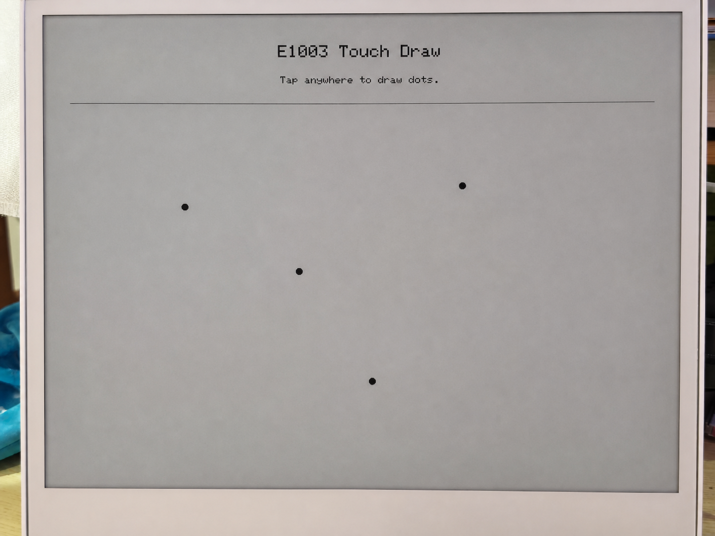
- Desenhar a tela de inicialização — exibe "E1003 Touch Draw" e uma mensagem no ePaper.
Loop de varredura do toque (loop()):
- Verificar a cada 30 ms — lê o registrador de status do GT911 para checar se um novo evento de toque está disponível.
- Ler as coordenadas de toque — extrai os valores brutos de X/Y dos registradores de dados de ponto do GT911 e depois os mapeia para coordenadas de display usando
mapTouchToDisplay()(que leva em conta qualquer diferença entre a resolução do toque e a resolução do display). - Debounce e verificação de distância — um novo ponto só é desenhado se:
- Pelo menos 450 ms tiverem se passado desde o último desenho, ou
- O ponto de toque tiver se movido pelo menos 12 pixels em relação ao último ponto desenhado.
- Desenhar no ePaper —
fillCircle()desenha um ponto preto sólido,drawCircle()adiciona um anel de halo cinza e entãoupdate()envia o buffer de quadro para o painel ePaper.
Cada chamada de update() aciona uma atualização completa do ePaper, o que leva cerca de 1–2 segundos no painel E1003. Isso é normal — ePaper não é um display de atualização rápida. A lógica de debounce (DRAW_MIN_MS = 450 ms) foi projetada para evitar sobrecarregar o painel com solicitações de atualização.
Pré-requisitos
Antes de executar este sketch:
- Instale a biblioteca Seeed_GFX via Arduino Library Manager.
- Defina PSRAM como OPI PSRAM no menu Tools — sem PSRAM, o buffer de display não pode ser alocado e
display_.width()retornará 0. - Defina Flash Size para 8 MB.
- Selecione a placa XIAO_ESP32S3.
Saída esperada
========================================
  E1003_TouchDraw - reTerminal E1003
========================================
[display] PSRAM found: yes, free PSRAM: 8159232 bytes
[display] Ready: 1872 x 1404
[touch] GT9xx found at 0x5D, product: 911
[touch] Touch range: 1872 x 1404, display: 1872 x 1404
[touch] Ready.
Após tocar na tela:
[touch] raw=(468,302) screen=(468,302)
[touch] raw=(920,756) screen=(920,756)
[touch] raw=(1400,1100) screen=(1400,1100)
Solução de problemas
P1: A saída serial ainda é visível em deep sleep — isso significa que o sketch de baixo consumo não está funcionando?
Isso é normal e não significa que o deep sleep falhou.
A saída serial que você vê é tratada pelo chip bridge USB-UART da placa base (não pelo próprio ESP32-S3). O chip bridge é alimentado diretamente pela conexão USB, portanto permanece ativo independentemente de o ESP32-S3 estar acordado ou em modo de suspensão. Na verdade, isso é uma escolha de projeto deliberada — garante que você sempre possa ver a saída serial e enviar novo firmware mesmo que o dispositivo entre em um ciclo rápido de deep sleep.
Para confirmar que o deep sleep está realmente ativo, verifique o log serial:
- Se você vir
[SLEEP] Entering deep sleep now.seguido de silêncio, o dispositivo está em deep sleep. - Se você vir
[ERROR] deep sleep did not start!, então algo deu errado.
P2: Como usar corretamente o sketch do RTC para diferentes cenários?
- Primeira inicialização
- Reinicializar / Ligar novamente
- Recalibrar
Cenário: Placa nova ou bateria CR1220 recém-substituída.
Você não precisa alterar nada — basta enviar o sketch como está.
Em uma placa nova, o sinal interno VL (Voltage Low) do PCF8563 é sempre 1 porque a bateria nunca alimentou o relógio. O sketch lê VL=1 na inicialização e grava automaticamente o timestamp de compilação no RTC.
Confirme que a sua USER CONFIGURATION está assim:
#define USE_COMPILE_TIME     // ← enabled ✓
// #define FORCE_SET_TIME   // ← keep commented ✓
→ Clique em Upload → Concluído.
Cenário: A placa já estava em funcionamento e foi reiniciada ou teve a alimentação desligada e ligada novamente.
Você não precisa fazer nada — apenas ligue.
A bateria CR1220 mantém o PCF8563 funcionando enquanto a alimentação principal está desligada. Na inicialização, o sketch lê VL=0 (bateria em bom estado) e ignora a gravação, preservando a hora armazenada. A saída serial mostrará a hora correta imediatamente.
Cenário: A hora do RTC está errada e precisa ser recalibrada.
Passo 1 — Forçar sobrescrita. Descomente FORCE_SET_TIME e então envie:
#define USE_COMPILE_TIME
#define FORCE_SET_TIME      // ← uncomment this line
→ Clique em Upload → A hora agora é forçada para o timestamp de compilação.
Passo 2 — Desativar a sobrescrita forçada. Imediatamente comente novamente e envie de novo:
#define USE_COMPILE_TIME
// #define FORCE_SET_TIME   // ← comment it back out
→ Clique em Upload → A partir de agora, cada reinicialização preserva a hora armazenada.
Suporte técnico e discussão sobre o produto
Obrigado por escolher nossos produtos! Estamos aqui para oferecer diferentes tipos de suporte para garantir que sua experiência com nossos produtos seja a mais tranquila possível. Oferecemos vários canais de comunicação para atender a diferentes preferências e necessidades.