Guia de Início Rápido Zigbee Seeed Studio XIAO ESP32C5 (Arduino)
Este tutorial orienta você na implementação de aplicações Zigbee na placa de desenvolvimento Seeed Studio XIAO ESP32-C5; esta placa combina conectividade Wi-Fi, Bluetooth Low Energy (BLE) e Zigbee, tornando-a perfeita para aplicações de IoT. Os exemplos neste guia utilizam o esp-arduino Zigbee SDK para dar vida à funcionalidade Zigbee.
Se você ainda não preparou sua Arduino IDE, consulte o Guia de Primeiros Passos.
Visão Geral do Zigbee
Zigbee é um protocolo de comunicação sem fio de baixa potência e baixa largura de banda baseado no padrão IEEE 802.15.4. Ele é voltado para cenários de IoT como automação residencial, cidades inteligentes e controle industrial, oferecendo capacidades robustas de rede em malha para comunicação confiável em ambientes dinâmicos.
- Forneceremos uma breve explicação do conteúdo relacionado ao Zigbee. Se você quiser ir diretamente para os exemplos de aplicação, também pode pular adiante.
Modelo de Dados Zigbee
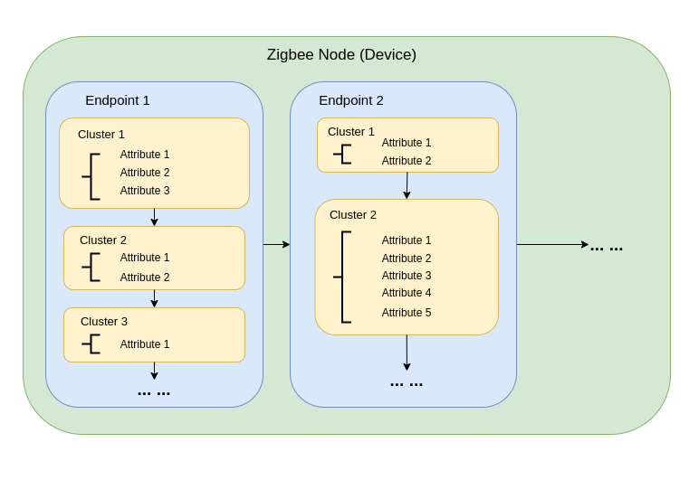
A comunicação Zigbee se baseia na Zigbee Cluster Library (ZCL), que define como os dispositivos organizam suas funcionalidades e interagem. Os principais componentes incluem:
-
Tipos de Dispositivo Dispositivos Zigbee (por exemplo, interruptores, sensores, lâmpadas) são predefinidos com comportamentos específicos, agrupados em Clusters funcionais.
-
Clusters Clusters são agrupamentos lógicos de:
- Atributos: Representam estados do dispositivo, como brilho ou temperatura.
- Comandos: Disparam ações, como ligar uma luz ou definir o brilho em 50%.
Exemplos:
- Cluster On/Off: Controla estados binários como energia.
- Cluster de Controle de Nível: Ajusta a intensidade ou brilho.
- Cluster de Medição de Temperatura: Envia leituras de temperatura.
- Cluster de Cenas: Salva e recupera configurações predefinidas.
-
Atributos e Comandos Atributos armazenam dados do dispositivo (por exemplo, estado, configuração), enquanto comandos iniciam ações.
Arquitetura de Rede Zigbee
Uma rede Zigbee consiste em três tipos principais de nós:
-
Zigbee Coordinator (ZC)
- Atua como o hub central da rede.
- Lida com a criação da rede, autenticação de dispositivos e alocação de endereços.
- Responsável por inicializar e gerenciar a rede.
- Cada rede Zigbee pode ter apenas um Coordenador.
-
Zigbee Router (ZR)
- Estende o alcance da rede ao retransmitir mensagens entre dispositivos.
- Suporta a entrada de dispositivos adicionais na rede.
- Normalmente alimentado pela rede elétrica para garantir operação constante e retransmissão confiável de mensagens.
- Routers alimentados por bateria são possíveis, mas menos comuns devido à maior demanda de energia.
-
Zigbee End Device (ZED)
- Dispositivos leves e eficientes em energia que se comunicam com um nó pai (um Coordenador ou Router).
- Não roteiam mensagens para outros dispositivos.
- Otimizados para operação com bateria e tipicamente entram em modos de suspensão para economizar energia.
-
Endereçamento e Roteamento:
- Zigbee usa um esquema de endereçamento de 16 bits. Os dispositivos se comunicam por meio de uma combinação de endereçamento direto e indireto.
- As decisões de roteamento são tomadas pelos Routers usando algoritmos como AODV (Ad hoc On-demand Distance Vector).
-
Gerenciamento de Energia:
- Dispositivos Finais Zigbee são otimizados para baixo consumo de energia. Eles frequentemente operam em modo de suspensão e só acordam quando necessário.
- Routers e o Coordenador são geralmente alimentados pela rede elétrica para disponibilidade constante.
Topologias de Rede
Zigbee suporta três topologias de rede principais, dependendo dos requisitos da aplicação e do ambiente:
1. Topologia em Malha
-
Um único Coordenador e vários Routers formam uma rede robusta e auto-recuperável.
-
Os dispositivos podem redirecionar dinamicamente as mensagens se um caminho de comunicação for interrompido, garantindo alta confiabilidade.
-
Ideal para redes em grande escala que exigem ampla cobertura e redundância.
-
Principais Características:
- Redirecionamento dinâmico garante alta confiabilidade.
- Suporta grandes redes com cobertura escalável.
- Mecanismos de auto-recuperação aumentam a tolerância a falhas.
2. Topologia em Árvore
-
O Coordenador atua como a raiz de uma estrutura hierárquica, com Routers formando os ramos.
-
Cada ramo pode ter vários Dispositivos Finais ou Routers adicionais, criando uma estrutura em forma de árvore.
-
A comunicação depende de caminhos hierárquicos, o que introduz potenciais pontos únicos de falha.
-
Principais Características:
- Funciona bem em ambientes estruturados.
- Mais fácil de configurar e gerenciar do que uma rede em malha.
- Vulnerável à falha de ramos, o que pode desconectar sub-redes inteiras.
3. Topologia em Estrela
-
Todos os dispositivos se comunicam diretamente com o Coordenador.
-
Simples de implantar, mas o Coordenador é um ponto único de falha.
-
Mais adequada para redes pequenas em que os dispositivos estão próximos ao Coordenador.
-
Principais Características:
- Fácil de configurar e gerenciar.
- Escalabilidade limitada devido a restrições de alcance e capacidade de dispositivos.
- A dependência do Coordenador para toda a comunicação reduz a tolerância a falhas.
Começando com Arduino Zigbee
Vamos demonstrar a funcionalidade de rede Zigbee para você usando Zigbee_On_Off_Light e Zigbee_On_Off_Switch no XIAO ESP32-C5 dentro da Arduino IDE.
Preparação de Hardware
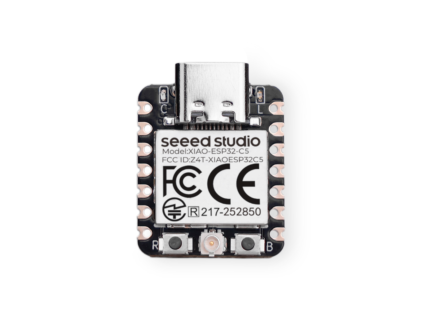
Você precisa preparar duas placas XIAO ESP32-C5.
| Seeed Studio XIAO ESP32-C5 |
|---|
 |
Zigbee_On_Off_Light
Você precisa selecionar uma placa XIAO ESP32-C5 como o dispositivo lâmpada.
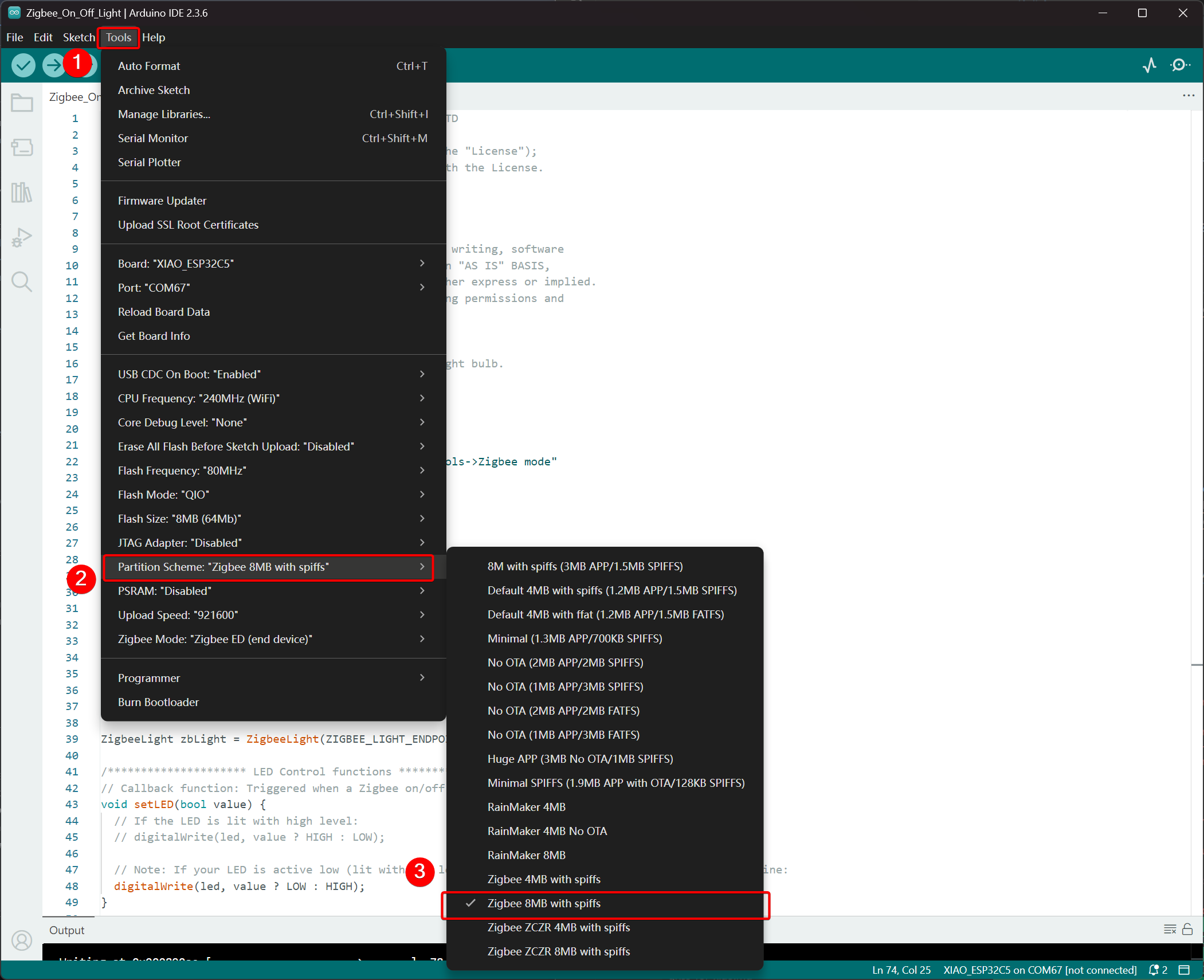
Passo 1. Definir Modo de Dispositivo Final
Precisamos configurar o XIAO ESP32-C5 como um Dispositivo Final Zigbee.
- Clique em Tools -> Zigbee Mode e selecione o modo como Zigbee ED (End Device).
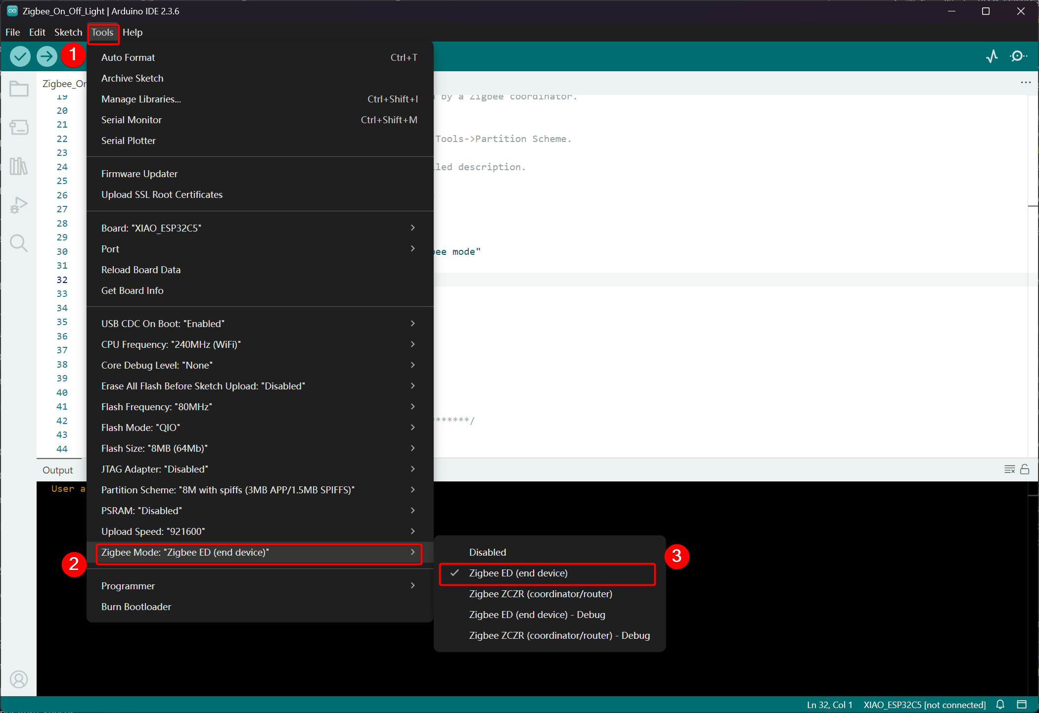
- Selecione o Esquema de Particionamento, vá em Tools -> Partition Scheme -> Zigbee 8MB with spiffs
A memória FLASH do XIAO ESP32-C5 é de 8MB. Ao selecionar um esquema de particionamento, é recomendado escolher Zigbee 8MB with spiffs.
Passo 2. Escrever o código
- Consulte o repositório oficial do Arduino para obter exemplos.
- Como alternativa, você pode selecionar o exemplo na Arduino IDE pelo caminho: File -> Examples -> Zigbee -> Zigbee_On_Off_Light.

- Modificar os exemplos
Para o XIAO ESP32-C5, selecionamos o LED onboard como a lâmpada emissora de luz, e o pino de controle é o GPIO27.
Zigbee_On_Off_Light.ino
// Copyright 2024 Espressif Systems (Shanghai) PTE LTD
//
// Licensed under the Apache License, Version 2.0 (the "License");
// you may not use this file except in compliance with the License.
// You may obtain a copy of the License at

//     http://www.apache.org/licenses/LICENSE-2.0
//
// Unless required by applicable law or agreed to in writing, software
// distributed under the License is distributed on an "AS IS" BASIS,
// WITHOUT WARRANTIES OR CONDITIONS OF ANY KIND, either express or implied.
// See the License for the specific language governing permissions and
// limitations under the License.

/**
 * @brief This example demonstrates simple Zigbee light bulb.
 *
 * Modified for Single Color LED control.
 */

#ifndef ZIGBEE_MODE_ED
#error "Zigbee end device mode is not selected in Tools->Zigbee mode"
#endif

#include "Zigbee.h"

/* Zigbee light bulb configuration */
#define ZIGBEE_LIGHT_ENDPOINT 10

// =========================================================
// Modification Area: Define your single-color LED pin here
// If your LED is connected to GPIO 2, set it to 2.
// If using the onboard standard LED, LED_BUILTIN can usually be used
// =========================================================
uint8_t led = 27;  // <--- Please modify the number here to your actual GPIO pin number

uint8_t button = BOOT_PIN;

ZigbeeLight zbLight = ZigbeeLight(ZIGBEE_LIGHT_ENDPOINT);

/********************* LED Control functions **************************/
// Callback function: Triggered when a Zigbee on/off command is received
void setLED(bool value) {
  // If the LED is lit with high level:
  // digitalWrite(led, value ? HIGH : LOW);

  // Note: If your LED is active low (lit with low level), use the line below instead of the above line:
  digitalWrite(led, value ? LOW : HIGH);
}

/********************* Arduino functions **************************/
void setup() {
  Serial.begin(115200);

  // Initialize LED pin as output mode
  pinMode(led, OUTPUT);
  // Turn off LED by default (assuming low level means on)
  digitalWrite(led, LOW);

  // Initialize button for factory reset
  pinMode(button, INPUT_PULLUP);

  // Optional: Set Zigbee device name and model (will be displayed in Home Assistant)
  zbLight.setManufacturerAndModel("Espressif", "SingleColorLight");

  // Set callback function for light state change
  zbLight.onLightChange(setLED);

  // Add Endpoint to Zigbee core
  Serial.println("Adding ZigbeeLight endpoint to Zigbee Core");
  Zigbee.addEndpoint(&zbLight);

  // Start Zigbee
  if (!Zigbee.begin()) {
    Serial.println("Zigbee failed to start!");
    Serial.println("Rebooting...");
    ESP.restart();
  }
  Serial.println("Connecting to network");
  while (!Zigbee.connected()) {
    Serial.print(".");
    delay(100);
  }
  Serial.println();
}

void loop() {
  // Check button for factory reset
  if (digitalRead(button) == LOW) {  // Button is pressed
    // Button debounce
    delay(100);
    int startTime = millis();
    while (digitalRead(button) == LOW) {
      delay(50);
      if ((millis() - startTime) > 3000) {
        // If pressed for more than 3 seconds, reset Zigbee and reboot
        Serial.println("Resetting Zigbee to factory and rebooting in 1s.");
        delay(1000);
        Zigbee.factoryReset();
      }
    }
    // Short press of the button: Toggle light state (local control)
    zbLight.setLight(!zbLight.getLightState());
  }
  delay(100);
}
- Faça o upload do código. Como ele está configurado para acender em nível baixo por padrão, pressione o botão de reset após o upload do código e o LED onboard acenderá.
Lógica de Implementação
- Verificação de Modo
#ifndef ZIGBEE_MODE_ED
#error "Zigbee end device mode is not selected..."
#endif
Isso força a seleção do modo "End Device" em Tools → Zigbee mode da Arduino IDE. Lâmpadas Zigbee normalmente atuam como End Devices de baixo consumo, em vez de Routers ou Coordinators.
- Incluir Arquivo de Cabeçalho
#include "Zigbee.h"
Importa a biblioteca Zigbee principal fornecida pela Espressif, que contém todas as classes e funções relacionadas a Zigbee.
- Definição de Configuração
#define ZIGBEE_LIGHT_ENDPOINT 10
Define o número do Endpoint Zigbee como 10. Um dispositivo Zigbee pode ter múltiplos endpoints, e a funcionalidade de lâmpada é atribuída ao endpoint 10 aqui.
- Área Modificável pelo Usuário (Parte Mais Importante)
uint8_t led = 27;        // Modify this to the actual GPIO pin connected to your LED
uint8_t button = BOOT_PIN;  // Usually GPIO0, used for factory reset
-
led = 27: O pino GPIO que controla o LED monocromático. Modifique esse número de acordo com a fiação do seu hardware. -
button = BOOT_PIN: Normalmente o botão BOOT (GPIO0) na placa de desenvolvimento ESP32, usado para redefinir a configuração Zigbee com um pressionamento longo.
- Criar Objeto de Lâmpada Zigbee
ZigbeeLight zbLight = ZigbeeLight(ZIGBEE_LIGHT_ENDPOINT);
Cria um objeto Zigbee Light que implementa o Cluster OnOff Zigbee HA (Home Automation) padrão para lâmpadas, oferecendo suporte ao controle remoto de ligar/desligar.
- Função de Callback de Controle do LED
void setLED(bool value) {
  digitalWrite(led, value ? LOW : HIGH);
}
Essa função é chamada automaticamente quando um comando de ligar/desligar é recebido da rede Zigbee.
- O código atual pressupõe que seu LED é ativo em nível baixo (comum quando um LED externo em uma placa de desenvolvimento ESP32 é conectado ao GND por meio de um resistor).
- Se o seu LED for ativo em nível alto (por exemplo, conectado diretamente ao VCC e aceso ao puxar o GPIO para baixo), modifique para a linha comentada abaixo:
digitalWrite(led, value ? HIGH : LOW);
- Explicação Detalhada da Função setup()
void setup() {
  Serial.begin(115200);                    // Enable serial debugging with baud rate 115200

  pinMode(led, OUTPUT);                    // Set the LED pin as output
  digitalWrite(led, LOW);                  // Turn off the LED by default (assuming active low, write LOW to ensure it's off)

  pinMode(button, INPUT_PULLUP);           // Set the button pin as input with pull-up resistor

  zbLight.setManufacturerAndModel("Espressif", "SingleColorLight");
  // Set the device manufacturer and model for friendly display on platforms like Home Assistant

  zbLight.onLightChange(setLED);
  // Key step: Bind the callback function for switch state changes, which calls setLED() when a Zigbee command is received

  Zigbee.addEndpoint(&zbLight);
  // Add the bulb endpoint to the Zigbee core

  if (!Zigbee.begin()) { ... ESP.restart(); }
  // Start the Zigbee stack; restart if it fails

  while (!Zigbee.connected()) { ... }
  // Wait for successful joining of the Zigbee network (pairing completed), print a dot every 100ms
}
- Explicação Detalhada da Função loop()
void loop() {
  if (digitalRead(button) == LOW) {        // Detect button press (low level)
    delay(100);                            // Simple debounce
    int startTime = millis();

    while (digitalRead(button) == LOW) {   // Continuously detect if the button is still pressed
      if ((millis() - startTime) > 3000) { // Long press for more than 3 seconds
        Zigbee.factoryReset();             // Factory reset Zigbee configuration (clear pairing information)
        delay(1000);
        // The device will automatically restart and enter pairing mode again
      }
    }

    // If short press: manually control the light's on/off state locally
    zbLight.setLight(!zbLight.getLightState());
    // This triggers the callback setLED() simultaneously to turn the light on/off locally
  }

  delay(100);
}
Zigbee_On_Off_Switch
Selecione outro XIAO ESP32-C5 como o interruptor. Ele formará uma rede Zigbee com o dispositivo de lâmpada anterior e então controlará o estado de ligar/desligar da lâmpada.
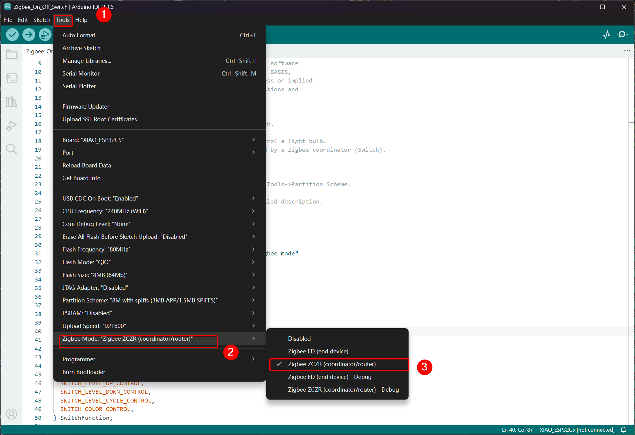
Passo 1. Definir para o Modo Coordinator
- Clique em Tools -> Zigbee Mode e selecione o modo como Zigbee ZCZR (Coordinator/Router).
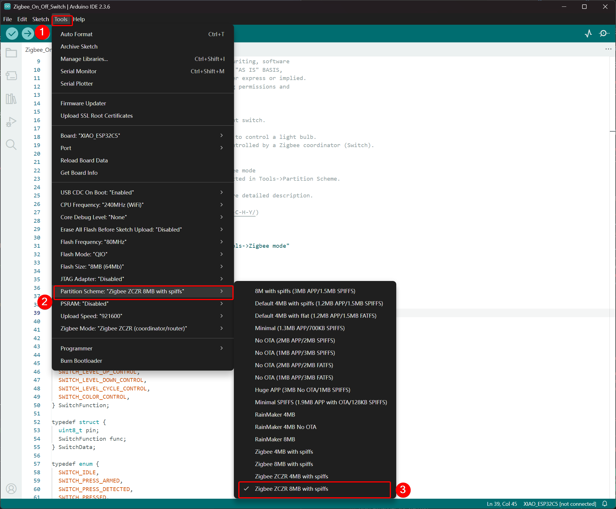
- Selecione Partition Scheme, vá em Tools -> Partition Scheme e escolha Zigbee 8MB ZCZR with spiffs.
A memória FLASH do XIAO ESP32-C5 é de 8MB. Ao selecionar um esquema de partição, recomenda-se escolher Zigbee 8MB ZCZR with spiffs.
Passo 2. Escrever o código
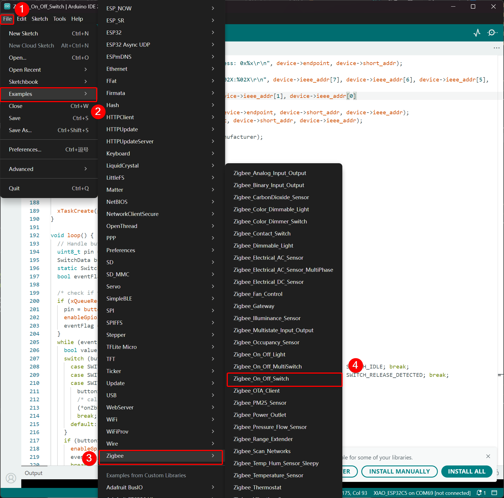
- Pule para o repositório oficial do Arduino para obter o código de exemplo.
- Alternativamente, você pode selecionar o exemplo na Arduino IDE pelo caminho: File -> Examples -> Zigbee -> Zigbee_On_Off_Swicth.
- Selecionamos o botão BOOT como interruptor. Para o XIAO ESP32-C5, o botão BOOT corresponde ao pino GPIO28.
Zigbee_On_Off_Switch.ino
// Copyright 2024 Espressif Systems (Shanghai) PTE LTD
//
// Licensed under the Apache License, Version 2.0 (the "License");
// you may not use this file except in compliance with the License.
// You may obtain a copy of the License at
//
//     http://www.apache.org/licenses/LICENSE-2.0
//
// Unless required by applicable law or agreed to in writing, software
// distributed under the License is distributed on an "AS IS" BASIS,
// WITHOUT WARRANTIES OR CONDITIONS OF ANY KIND, either express or implied.
// See the License for the specific language governing permissions and
// limitations under the License.

/**
 * @brief This example demonstrates simple Zigbee light switch.
 *
 * The example demonstrates how to use Zigbee library to control a light bulb.
 * The light bulb is a Zigbee end device, which is controlled by a Zigbee coordinator (Switch).
 * Button switch and Zigbee runs in separate tasks.
 *
 * Proper Zigbee mode must be selected in Tools->Zigbee mode
 * and also the correct partition scheme must be selected in Tools->Partition Scheme.
 *
 * Please check the README.md for instructions and more detailed description.
 *
 * Created by Jan Procházka (https://github.com/P-R-O-C-H-Y/)
 */

#ifndef ZIGBEE_MODE_ZCZR
#error "Zigbee coordinator mode is not selected in Tools->Zigbee mode"
#endif

#include "Zigbee.h"

/* Zigbee switch configuration */
#define SWITCH_ENDPOINT_NUMBER 5

#define GPIO_INPUT_IO_TOGGLE_SWITCH BOOT_PIN
#define PAIR_SIZE(TYPE_STR_PAIR)    (sizeof(TYPE_STR_PAIR) / sizeof(TYPE_STR_PAIR[0]))

typedef enum {
  SWITCH_ON_CONTROL,
  SWITCH_OFF_CONTROL,
  SWITCH_ONOFF_TOGGLE_CONTROL,
  SWITCH_LEVEL_UP_CONTROL,
  SWITCH_LEVEL_DOWN_CONTROL,
  SWITCH_LEVEL_CYCLE_CONTROL,
  SWITCH_COLOR_CONTROL,
} SwitchFunction;

typedef struct {
  uint8_t pin;
  SwitchFunction func;
} SwitchData;

typedef enum {
  SWITCH_IDLE,
  SWITCH_PRESS_ARMED,
  SWITCH_PRESS_DETECTED,
  SWITCH_PRESSED,
  SWITCH_RELEASE_DETECTED,
} SwitchState;

static SwitchData buttonFunctionPair[] = {{GPIO_INPUT_IO_TOGGLE_SWITCH, SWITCH_ONOFF_TOGGLE_CONTROL}};

ZigbeeSwitch zbSwitch = ZigbeeSwitch(SWITCH_ENDPOINT_NUMBER);

static bool light_state = false;

/********************* Zigbee functions **************************/
static void onZbButton(SwitchData *button_func_pair) {
  if (button_func_pair->func == SWITCH_ONOFF_TOGGLE_CONTROL) {
    // Send toggle command to the light
    Serial.println("Toggling light");
    zbSwitch.lightToggle();
  }
}

static void onLightStateChange(bool state) {
  if (state != light_state) {
    light_state = state;
    Serial.printf("Light state changed to %d\r\n", state);
  }
}

/********************* Periodic task ***************************/
void periodicTask(void *arg) {
  while (true) {
    // print the bound lights every 10 seconds
    static uint32_t lastPrint = 0;
    if (millis() - lastPrint > 10000) {
      lastPrint = millis();
      zbSwitch.printBoundDevices(Serial);
    }

    // Poll light state every second
    static uint32_t lastPoll = 0;
    if (millis() - lastPoll > 1000) {
      lastPoll = millis();
      zbSwitch.getLightState();
    }
    vTaskDelay(1000 / portTICK_PERIOD_MS);
  }
}

/********************* GPIO functions **************************/
static QueueHandle_t gpio_evt_queue = NULL;

static void IRAM_ATTR onGpioInterrupt(void *arg) {
  xQueueSendFromISR(gpio_evt_queue, (SwitchData *)arg, NULL);
}

static void enableGpioInterrupt(bool enabled) {
  for (int i = 0; i < PAIR_SIZE(buttonFunctionPair); ++i) {
    if (enabled) {
      enableInterrupt((buttonFunctionPair[i]).pin);
    } else {
      disableInterrupt((buttonFunctionPair[i]).pin);
    }
  }
}

/********************* Arduino functions **************************/
void setup() {
  Serial.begin(115200);

  //Optional: set Zigbee device name and model
  zbSwitch.setManufacturerAndModel("Espressif", "ZigbeeSwitch");

  //Optional to allow multiple light to bind to the switch
  zbSwitch.allowMultipleBinding(true);

  zbSwitch.onLightStateChange(onLightStateChange);

  //Add endpoint to Zigbee Core
  Serial.println("Adding ZigbeeSwitch endpoint to Zigbee Core");
  Zigbee.addEndpoint(&zbSwitch);

  //Open network for 180 seconds after boot
  Zigbee.setRebootOpenNetwork(180);

  // Init button switch
  for (int i = 0; i < PAIR_SIZE(buttonFunctionPair); i++) {
    pinMode(buttonFunctionPair[i].pin, INPUT_PULLUP);
    /* create a queue to handle gpio event from isr */
    gpio_evt_queue = xQueueCreate(10, sizeof(SwitchData));
    if (gpio_evt_queue == 0) {
      Serial.println("Queue creating failed, rebooting...");
      ESP.restart();
    }
    attachInterruptArg(buttonFunctionPair[i].pin, onGpioInterrupt, (void *)(buttonFunctionPair + i), FALLING);
  }

  // When all EPs are registered, start Zigbee with ZIGBEE_COORDINATOR mode
  if (!Zigbee.begin(ZIGBEE_COORDINATOR)) {
    Serial.println("Zigbee failed to start!");
    Serial.println("Rebooting...");
    ESP.restart();
  }

  Serial.println("Waiting for Light to bound to the switch");
  //Wait for switch to bound to a light:
  while (!zbSwitch.bound()) {
    Serial.printf(".");
    delay(500);
  }

  // Optional: List all bound devices and read manufacturer and model name
  std::list<zb_device_params_t *> boundLights = zbSwitch.getBoundDevices();
  for (const auto &device : boundLights) {
    Serial.printf("Device on endpoint %d, short address: 0x%x\r\n", device->endpoint, device->short_addr);
    Serial.printf(
      "IEEE Address: %02X:%02X:%02X:%02X:%02X:%02X:%02X:%02X\r\n", device->ieee_addr[7], device->ieee_addr[6], device->ieee_addr[5], device->ieee_addr[4],
      device->ieee_addr[3], device->ieee_addr[2], device->ieee_addr[1], device->ieee_addr[0]
    );
    char *manufacturer = zbSwitch.readManufacturer(device->endpoint, device->short_addr, device->ieee_addr);
    char *model = zbSwitch.readModel(device->endpoint, device->short_addr, device->ieee_addr);
    if (manufacturer != nullptr) {
      Serial.printf("Light manufacturer: %s\r\n", manufacturer);
    }
    if (model != nullptr) {
      Serial.printf("Light model: %s\r\n", model);
    }
  }

  Serial.println();

  xTaskCreate(periodicTask, "periodicTask", 1024 * 4, NULL, 10, NULL);
}

void loop() {
  // Handle button switch in loop()
  uint8_t pin = 0;
  SwitchData buttonSwitch;
  static SwitchState buttonState = SWITCH_IDLE;
  bool eventFlag = false;

  /* check if there is any queue received, if yes read out the buttonSwitch */
  if (xQueueReceive(gpio_evt_queue, &buttonSwitch, portMAX_DELAY)) {
    pin = buttonSwitch.pin;
    enableGpioInterrupt(false);
    eventFlag = true;
  }
  while (eventFlag) {
    bool value = digitalRead(pin);
    switch (buttonState) {
      case SWITCH_IDLE:           buttonState = (value == LOW) ? SWITCH_PRESS_DETECTED : SWITCH_IDLE; break;
      case SWITCH_PRESS_DETECTED: buttonState = (value == LOW) ? SWITCH_PRESS_DETECTED : SWITCH_RELEASE_DETECTED; break;
      case SWITCH_RELEASE_DETECTED:
        buttonState = SWITCH_IDLE;
        /* callback to button_handler */
        (*onZbButton)(&buttonSwitch);
        break;
      default: break;
    }
    if (buttonState == SWITCH_IDLE) {
      enableGpioInterrupt(true);
      eventFlag = false;
      break;
    }
    vTaskDelay(10 / portTICK_PERIOD_MS);
  }
}
- Faça o upload do código e abra o Serial Monitor; as informações de rede serão impressas. Para o efeito final, pule para Result
Lógica de Implementação
- Verificação de Modo
#ifndef ZIGBEE_MODE_ZCZR
#error "Zigbee coordinator mode is not selected in Tools->Zigbee mode"
#endif
O interruptor neste exemplo atua como um Coordenador Zigbee (ZC/ZR), responsável por formar a rede e controlar outros dispositivos.
- Inclusão do Arquivo de Cabeçalho
#include "Zigbee.h"
Importa a biblioteca Zigbee principal fornecida pela Espressif, contendo todas as classes e funções necessárias para operações Zigbee.
- Definições de Configuração
#define SWITCH_ENDPOINT_NUMBER 5
#define GPIO_INPUT_IO_TOGGLE_SWITCH BOOT_PIN
SWITCH_ENDPOINT_NUMBER 5: Define o número do endpoint (5) usado pela funcionalidade de interruptor Zigbee.GPIO_INPUT_IO_TOGGLE_SWITCH BOOT_PIN: Define o pino físico do botão como o pino BOOT (geralmente GPIO0). Este botão acionará uma ação de alternância.
- Estruturas de Dados e Configuração do Botão
typedef enum { ... } SwitchFunction;
typedef struct { uint8_t pin; SwitchFunction func; } SwitchData;

static SwitchData buttonFunctionPair[] = {{GPIO_INPUT_IO_TOGGLE_SWITCH, SWITCH_ONOFF_TOGGLE_CONTROL}};
- Define possíveis funções do interruptor (alternar, ligar, desligar, controle de nível, etc.).
- O array
buttonFunctionPairmapeia pinos físicos para suas funções. Atualmente, apenas um botão está configurado: o pino BOOT executa uma ação de alternância quando pressionado.
- Criar Objeto Zigbee Switch
ZigbeeSwitch zbSwitch = ZigbeeSwitch(SWITCH_ENDPOINT_NUMBER);
Cria um objeto ZigbeeSwitch que implementa um dispositivo padrão de interruptor Liga/Desliga Zigbee, capaz de enviar comandos para lâmpadas vinculadas via binding Zigbee.
- Funções de Callback Zigbee
static void onZbButton(SwitchData *button_func_pair) {
  if (button_func_pair->func == SWITCH_ONOFF_TOGGLE_CONTROL) {
    zbSwitch.lightToggle();  // Send toggle command to all bound lights
  }
}

static void onLightStateChange(bool state) {
  // Called when a bound light reports a state change
  Serial.printf("Light state changed to %d\r\n", state);
}
onZbButton: Executado quando um pressionamento de botão válido é detectado; envia um comando de alternância para todas as luzes vinculadas.onLightStateChange: Callback acionado quando qualquer luz vinculada reporta seu novo estado de ligado/desligado (útil para sincronização).
- Tarefa Periódica
void periodicTask(void *arg) {
  while (true) {
    // Every 10 seconds: print all currently bound devices
    // Every 1 second: poll the current state of bound lights
    vTaskDelay(1000 / portTICK_PERIOD_MS);
  }
}
Uma tarefa FreeRTOS separada que periodicamente imprime informações de dispositivos vinculados e consulta estados das luzes para manter o coordenador sincronizado.
- Interrupção GPIO e Tratamento da Fila
static QueueHandle_t gpio_evt_queue = NULL;

static void IRAM_ATTR onGpioInterrupt(void *arg) {
  xQueueSendFromISR(gpio_evt_queue, (SwitchData *)arg, NULL);
}
- Usa uma fila do FreeRTOS para passar com segurança eventos de pressionamento de botão da ISR (rotina de atendimento de interrupção) para o loop principal.
- A interrupção é anexada à borda de descida no pino do botão para detecção rápida.
- Explicação Detalhada da Função setup()
void setup() {
  Serial.begin(115200);

  zbSwitch.setManufacturerAndModel("Espressif", "ZigbeeSwitch");
  zbSwitch.allowMultipleBinding(true);  // Allow controlling multiple lights simultaneously
  zbSwitch.onLightStateChange(onLightStateChange);

  Zigbee.addEndpoint(&zbSwitch);

  Zigbee.setRebootOpenNetwork(180);  // Open network for pairing for 180 seconds after boot

  // Initialize button pins and attach interrupts
  pinMode(... , INPUT_PULLUP);
  attachInterruptArg(... , FALLING);

  if (!Zigbee.begin(ZIGBEE_COORDINATOR)) { ... ESP.restart(); }

  // Block until at least one light is bound
  while (!zbSwitch.bound()) { Serial.print("."); delay(500); }

  // Print detailed information about all bound lights (address, manufacturer, model)
  zbSwitch.printBoundDevices(Serial);

  // Create periodic task
  xTaskCreate(periodicTask, "periodicTask", 1024 * 4, NULL, 10, NULL);
}
- Configura as propriedades do dispositivo interruptor e permite múltiplos bindings.
- Abre a rede por 180 segundos para facilitar o pareamento das lâmpadas.
- Inicia o Zigbee no modo Coordenador.
- Aguarda até que pelo menos uma luz seja vinculada com sucesso e então imprime informações detalhadas de binding.
- Inicia a tarefa de monitoramento periódico.
- Explicação Detalhada da Função loop()
void loop() {
  // Receive button events from queue
  if (xQueueReceive(gpio_evt_queue, &buttonSwitch, portMAX_DELAY)) {
    // Disable further interrupts to prevent bounce interference
    enableGpioInterrupt(false);

    // State machine for reliable button detection:
    // - Detect press → confirm sustained press → detect release → execute action
    static SwitchState buttonState = SWITCH_IDLE;
    // ... state transitions ...

    if (buttonState == SWITCH_IDLE) {
      // Button fully released → execute toggle command
      onZbButton(&buttonSwitch);
      // Re-enable interrupts for next press
      enableGpioInterrupt(true);
    }
  }
}
- Implementa um manipulador de botão robusto com antirruído (debounce) usando uma máquina de estados.
- Garante um ciclo completo de pressionar e soltar antes de enviar o comando de alternância.
- Impede reentrada de interrupção durante o processamento para operação estável.
Resultado
Conecte as duas placas XIAO ESP32-C5 ao seu computador e abra o Monitor Serial. Se o dispositivo lâmpada imprimir Connecting to network, isso indica que ele ingressou na rede Zigbee, e o dispositivo interruptor imprimirá as informações dos dispositivos que ingressaram na rede. Quando você pressionar o botão BOOT no dispositivo interruptor, o LED USER onboard do dispositivo lâmpada irá alternar.
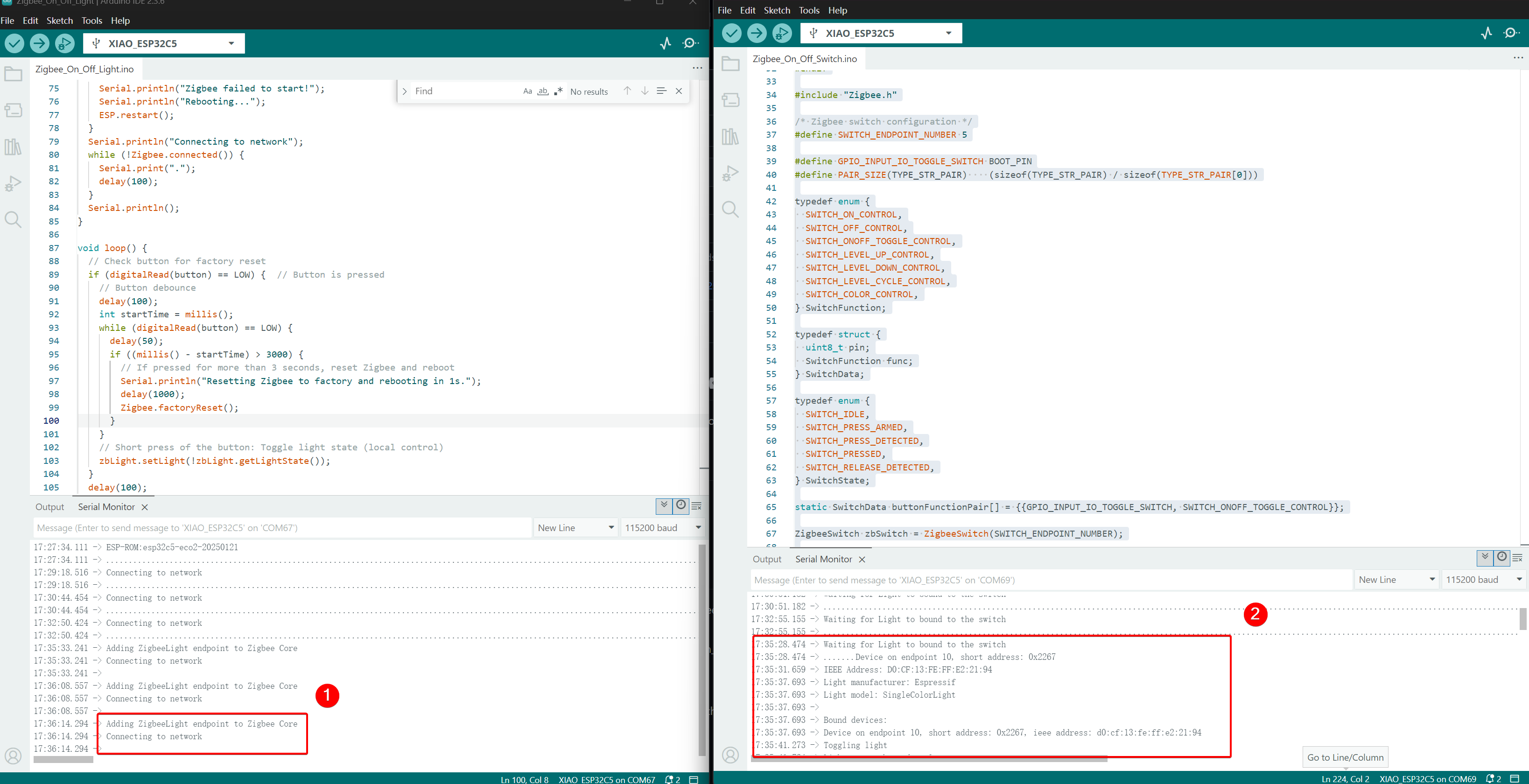
- Efeito de controle: quando o botão BOOT é pressionado, o LED USER no outro XIAO ESP32-C5 irá alternar.
Suporte Técnico & Discussão de Produto
Obrigado por escolher nossos produtos! Estamos aqui para oferecer diferentes tipos de suporte para garantir que sua experiência com nossos produtos seja a mais tranquila possível. Oferecemos vários canais de comunicação para atender a diferentes preferências e necessidades.