Multiplexação de pinos com Seeed Studio XIAO nRF54LM20A Sense
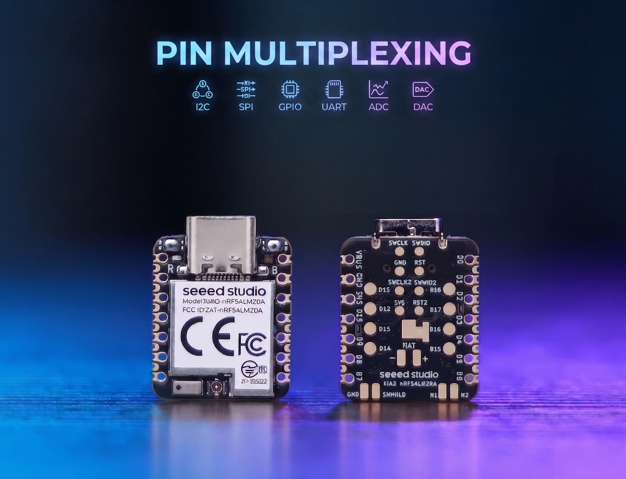
O XIAO nRF54LM20A possui recursos abundantes de pinos e oferece suporte nativo ao desenvolvimento com várias interfaces periféricas padrão, incluindo Digital, Analógica, SPI e IIC. Este artigo demonstra implementações relevantes com casos de aplicação prática.
Este tutorial foi desenvolvido com base no sistema de build PlatformIO e no Zephyr RTOS. Se você não está familiarizado com a criação de um projeto para o XIAO nRF54LM20A no PlatformIO, você pode ir para Getting Sarted With Seeed Studio XIAO nRF54LM20A Sense
Digital
Os pinos digitais realizam principalmente o controle liga/desliga de sensores e atuadores externos, por meio da saída de níveis lógicos alto e baixo. Combinado com a placa de expansão Grove Base for XIAO e módulos periféricos padrão Grove, esta seção detalha a lógica de driver de baixo nível e os métodos práticos de invocação dos pinos digitais no XIAO nRF54LM20A.
Preparação de hardware
| Seeed Studio XIAO nRF54LM20A Sense | Seeed Studio Grove Base for XIAO | Grove - Piezo Buzzer | Grove - Button |
|---|---|---|---|
 |  |  | |
Preparação de software
De acordo com o pinout do XIAO nRF54LM20A, P1.0 pode ser selecionado como o pino de controle para o Grove-Button, e P1.31 pode ser selecionado como o pino de controle para o Grove-Pizero Buzzer.
- Para o pinout do XIAO nRF54LM20A, clique em XIAO nRF54LM20A Pin List para ver os detalhes.
Escreva o programa para main.c
/*
 * Grove Button (P1.0) + Grove Buzzer (P1.31) - Digital mode
 * Button pressed → Buzzer ON; Button released → Buzzer OFF
 *
 * NOTE: Requires an ACTIVE buzzer (built-in oscillator).
 *       A passive piezo buzzer needs PWM — use plan B instead.
 */

#include <zephyr/kernel.h>
#include <zephyr/device.h>
#include <zephyr/drivers/gpio.h>
#include <zephyr/sys/printk.h>

#define BUTTON_PIN 0  /* P1.0 - Grove Button - D0 */
#define BUZZER_PIN 31 /* P1.31 - Grove Buzzer - D1 */

int main(void)
{
	const struct device *gpio1_dev = DEVICE_DT_GET(DT_NODELABEL(gpio1));

	printk("=== Grove Button + Buzzer (Digital Mode) ===\n");

	if (!device_is_ready(gpio1_dev))
	{
		printk("ERROR: gpio1 device is not ready!\n");
		return -1;
	}
	printk("gpio1 device ready: %s\n", gpio1_dev->name);

	/* Grove Button has onboard pull-down; HIGH = pressed */
	gpio_pin_configure(gpio1_dev, BUTTON_PIN, GPIO_INPUT);

	/* Buzzer: HIGH = on */
	gpio_pin_configure(gpio1_dev, BUZZER_PIN, GPIO_OUTPUT_INACTIVE);

	printk("Button:  P1.%d (input)\n", BUTTON_PIN);
	printk("Buzzer:  P1.%d (output)\n", BUZZER_PIN);
	printk("Press the button to turn on the buzzer...\n");

	int last_val = 0;

	while (1)
	{
		int val = gpio_pin_get(gpio1_dev, BUTTON_PIN);
		if (val >= 0)
		{
			gpio_pin_set(gpio1_dev, BUZZER_PIN, val);

			/* Only print on state change to avoid log spam */
			if (val != last_val)
			{
				printk("Button %s → Buzzer %s\n",
				       val ? "PRESSED " : "released",
				       val ? "ON" : "OFF");
				last_val = val;
			}
		}
		k_msleep(10);
	}

	return 0;
}
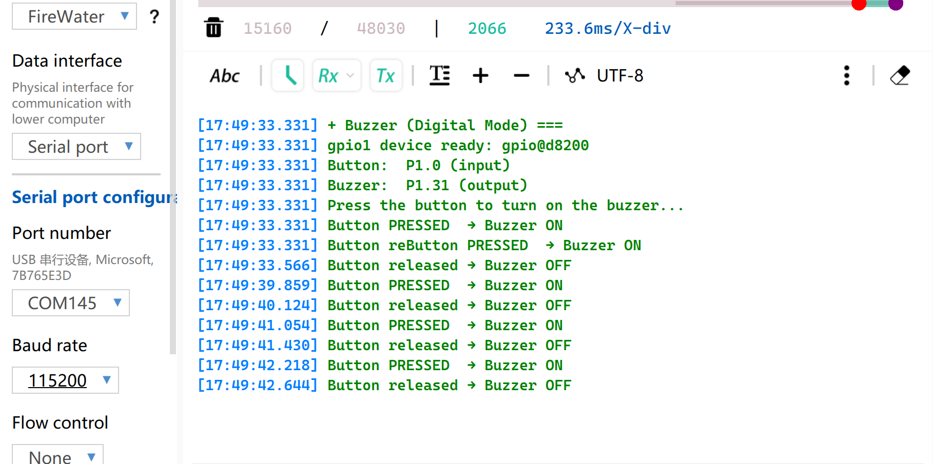
Resultado
Após gravar o firmware, pressione o botão e o buzzer irá apitar. E a porta serial irá imprimir o status.
Observe que é necessário definir a taxa de baud para 115200. Se você abrir o Monitor diretamente no VS, é recomendável definir a taxa de baud no arquivo .ini
PWM
PWM é uma função de saída de forma de onda temporizada implementada com base em GPIOs de saída digital. Ela alterna rapidamente os níveis do pino em uma frequência fixa e ajusta dinamicamente o ciclo de trabalho do nível alto dentro de um único ciclo, de modo a fornecer sinais analógicos equivalentes para os periféricos. Em aplicações de engenharia prática, PWM é amplamente utilizado para controle preciso de ângulo de servomotores e ajuste suave de brilho de LEDs.
Preparação de hardware
| Seeed Studio XIAO nRF54LM20A Sense | Seeed Studio Grove Base for XIAO | Grove - Servo |
|---|---|---|
|  | |
Preparação de software
De acordo com o pinout do XIAO nRF54LM20A, P1.0 pode ser selecionado como o pino de controle para o Grove-Servo.
- Para o pinout do XIAO nRF54LM20A, clique em XIAO nRF54LM20A Pin List para ver os detalhes.
- Modifique o arquivo de device tree
app.overlay. Para a função de saída PWM, a instância de hardware deve ser explicitamente vinculada ao nópwm20,pwm21oupwm22. A saída padrão do console UART do sistema está anexada ao nóuart20.
app.overlay
/*
 * UART20 (console) + PWM20 (servo) configuration for XIAO nRF54LM20A.
 *
 * Note: spi23 and uart20 share the same peripheral instance (0xc6000),
 * so only one can be active at a time. SD card via spi23 is removed here.
 */

/ {
	chosen {
		zephyr,console    = &uart20;
		nordic,rpc-uart   = &uart20;
		zephyr,shell-uart = &uart20;
	};
};

/* ── UART20 (console, TX: P1.11 / RX: P1.10) ── */
&uart20 {
	current-speed = <115200>;
	status = "okay";
};

&uart20_default {
	group1 {
		psels = <NRF_PSEL(UART_TX, 1, 11)>;
	};
	group2 {
		psels = <NRF_PSEL(UART_RX, 1, 10)>;
		bias-pull-up;
	};
};

&uart20_sleep {
	group1 {
		psels = <NRF_PSEL(UART_TX, 1, 11)>,
			<NRF_PSEL(UART_RX, 1, 10)>;
		low-power-enable;
	};
};

/* ── PWM20 (servo, P1.0) ── */
&pwm20 {
	status = "okay";
	pinctrl-0 = <&servo_pwm20_default>;
	pinctrl-1 = <&servo_pwm20_sleep>;
	pinctrl-names = "default", "sleep";
};

&pinctrl {
	servo_pwm20_default: servo_pwm20_default {
		group1 {
			psels = <NRF_PSEL(PWM_OUT0, 1, 0)>; /* P1.0 */
		};
	};
	servo_pwm20_sleep: servo_pwm20_sleep {
		group1 {
			psels = <NRF_PSEL(PWM_OUT0, 1, 0)>;
			low-power-enable;
		};
	};
};
- Modifique o arquivo
prj.confpara habilitar as configurações de PWM relevantes.
CONFIG_PWM=y
CONFIG_SERIAL=y
CONFIG_PRINTK=y
CONFIG_UART_CONSOLE=y
- Escreva o programa main.c para implementar a função de controle do servo por PWM e configurar parâmetros como o período do PWM.
/*
 * Servo control on P1.0 via PWM (50 Hz).
 * Sweeps 0→180° at ~100°/s, then returns 180→0° at ~33°/s.
 * Current angle is printed to serial console.
 */

#include <zephyr/kernel.h>
#include <zephyr/device.h>
#include <zephyr/drivers/pwm.h>
#include <zephyr/sys/printk.h>

/* Standard servo: 50 Hz period, 0.5–2.5 ms pulse for 0–180° */
#define SERVO_PERIOD_NS PWM_MSEC(20)
#define SERVO_MIN_NS PWM_USEC(500)
#define SERVO_MAX_NS PWM_USEC(2500)

#define SERVO_CHANNEL 0

/* 10 ms/step → ~100°/s forward; 30 ms/step → ~33°/s return */
#define STEP_FWD_MS 30
#define STEP_RET_MS 30

static const struct device *pwm_dev = DEVICE_DT_GET(DT_NODELABEL(pwm20));

static int set_angle(int degrees)
{
    uint32_t pulse = SERVO_MIN_NS +
                     (uint32_t)((uint64_t)degrees *
                                (SERVO_MAX_NS - SERVO_MIN_NS) / 180U);
    return pwm_set(pwm_dev, SERVO_CHANNEL, SERVO_PERIOD_NS, pulse,
                   PWM_POLARITY_NORMAL);
}

int main(void)
{
    printk("=== boot ===\n");

    if (!device_is_ready(pwm_dev))
    {
        printk("Error: PWM device not ready\n");
        return -1;
    }

    printk("Servo control started on P1.0\n");

    while (1)
    {
        /* 0° → 180° (faster) */
        for (int a = 0; a <= 180; a++)
        {
            if (set_angle(a) != 0)
            {
                printk("PWM error at %d deg\n", a);
            }
            else
            {
                printk("Angle: %d deg\n", a);
            }
            k_msleep(STEP_FWD_MS);
        }

        /* 180° → 0° (slower) */
        for (int a = 180; a >= 0; a--)
        {
            if (set_angle(a) != 0)
            {
                printk("PWM error at %d deg\n", a);
            }
            else
            {
                printk("Angle: %d deg\n", a);
            }
            k_msleep(STEP_RET_MS);
        }
    }

    return 0;
}
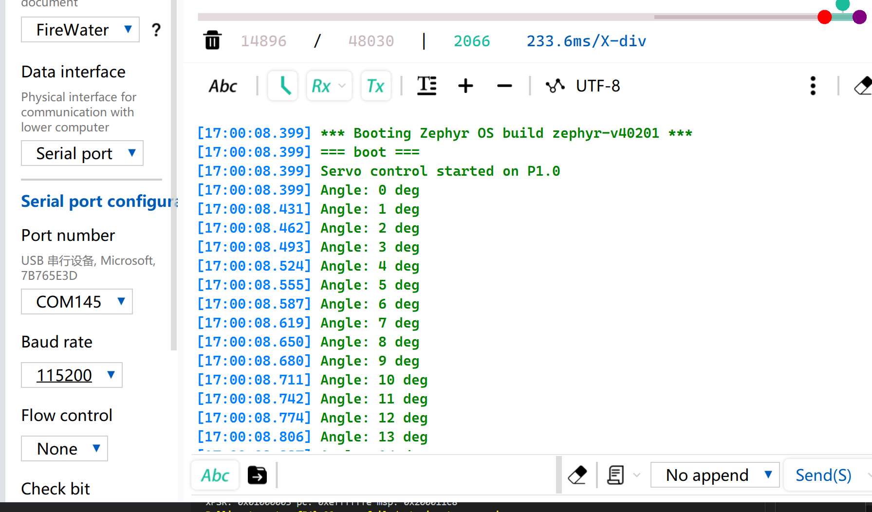
Resultado
Após a gravação do firmware, o servo gira de 0° a 180° a uma velocidade de 33 radianos por segundo e depois gira de volta para 0°.
Enquanto isso, o ângulo atual do servo será impresso via porta serial USB.
Analógico
A E/S analógica é baseada em um Conversor Analógico-Digital (ADC) e é usada principalmente para capturar sinais contínuos de tensão analógica fornecidos por sensores externos. Após obter os valores digitais de amostragem brutos (Raw Data), eles podem ser mapeados para valores reais de medição de engenharia usando algoritmos específicos de conversão linear ou não linear. Essa função é amplamente utilizada em cenários como amostragem de tensão de bateria e monitoramento em tempo real de grandezas físicas, incluindo umidade do solo e temperatura ambiente.
Preparação de hardware
| Seeed Studio XIAO nRF54LM20A Sense | Seeed Studio Grove Base for XIAO | Grove - Capacitive Soil Moisture Sensor |
|---|---|---|
|  | |
Preparação de software
De acordo com o pinout do XIAO nRF54LM20A, defina o P1.00 como o pino de saída PWM.
- Para o pinout do XIAO nRF54LM20A, clique em XIAO nRF54LM20A Pin List para ver os detalhes.
- Modifique o arquivo de device tree. O pino P1.00 corresponde ao canal 0 do ADC e precisa ser vinculado ao nó do device tree.
/*
 * UART20 (console) + ADC channel 0 (P1.0 / AIN0) for XIAO nRF54LM20A.
 */

/ {
	chosen {
		zephyr,console    = &uart20;
		nordic,rpc-uart   = &uart20;
		zephyr,shell-uart = &uart20;
	};

	zephyr,user {
		io-channels = <&adc 0>;
	};
};


/* ── UART20 (console, TX: P1.11 / RX: P1.10) ── */
&uart20 {
	current-speed = <115200>;
	status = "okay";
};

&uart20_default {
	group1 {
		psels = <NRF_PSEL(UART_TX, 1, 11)>;
	};
	group2 {
		psels = <NRF_PSEL(UART_RX, 1, 10)>;
		bias-pull-up;
	};
};

&uart20_sleep {
	group1 {
		psels = <NRF_PSEL(UART_TX, 1, 11)>,
			<NRF_PSEL(UART_RX, 1, 10)>;
		low-power-enable;
	};
};
- Modifique o arquivo
prj.confpara habilitar as configurações relacionadas ao ADC.
CONFIG_ADC=y
CONFIG_ADC_NRFX_SAADC=y
CONFIG_SERIAL=y
CONFIG_PRINTK=y
CONFIG_UART_CONSOLE=y
- Escreva o programa main.c, use o pino P1.00 como pino de entrada analógica e envie o valor lido pela porta serial USB a cada 500 ms.
/*
 * Read ADC on P1.0 (AIN0, channel 0) and print raw value every 500 ms.
 */

#include <zephyr/kernel.h>
#include <zephyr/drivers/adc.h>
#include <zephyr/sys/printk.h>

static const struct adc_dt_spec adc_ch =
    ADC_DT_SPEC_GET(DT_PATH(zephyr_user));

int main(void)
{
    int ret;

    if (!adc_is_ready_dt(&adc_ch))
    {
        printk("ADC not ready\n");
        return -1;
    }

    ret = adc_channel_setup_dt(&adc_ch);
    if (ret < 0)
    {
        printk("ADC channel setup failed: %d\n", ret);
        return ret;
    }

    int16_t buf;
    struct adc_sequence seq = {
        .buffer = &buf,
        .buffer_size = sizeof(buf),
    };
    adc_sequence_init_dt(&adc_ch, &seq);

    while (1)
    {
        ret = adc_read_dt(&adc_ch, &seq);
        if (ret < 0)
        {
            printk("ADC read error: %d\n", ret);
        }
        else
        {
            printk("ADC raw: %d\n", buf);
        }
        k_msleep(500);
    }

    return 0;
}
Resultado
Após gravar o programa, insira o Grove-Capacitive Soil Moisture Sensor em vasos de plantas domésticas.
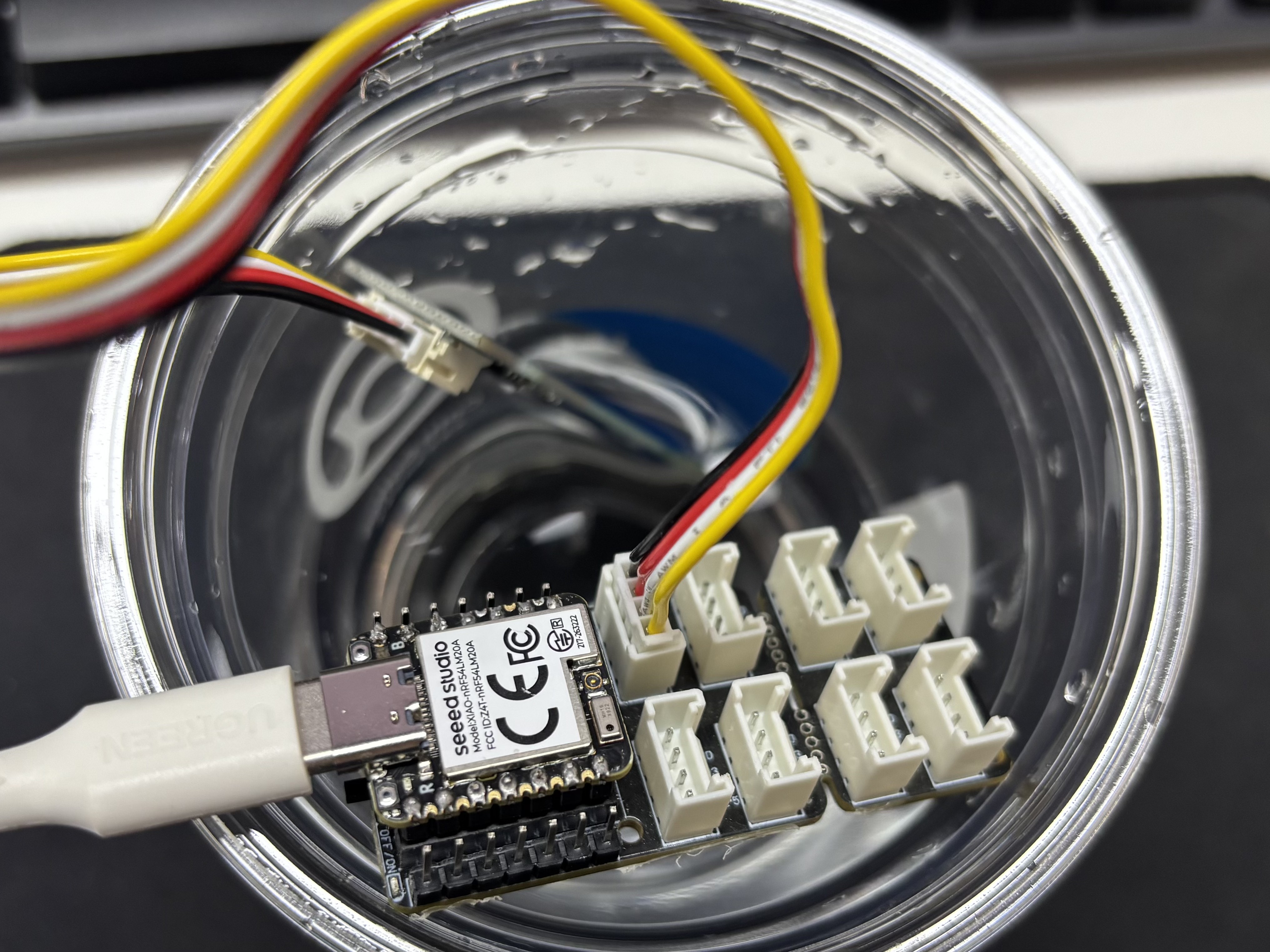
Abra o assistente de porta serial no seu computador e observe os valores de saída.
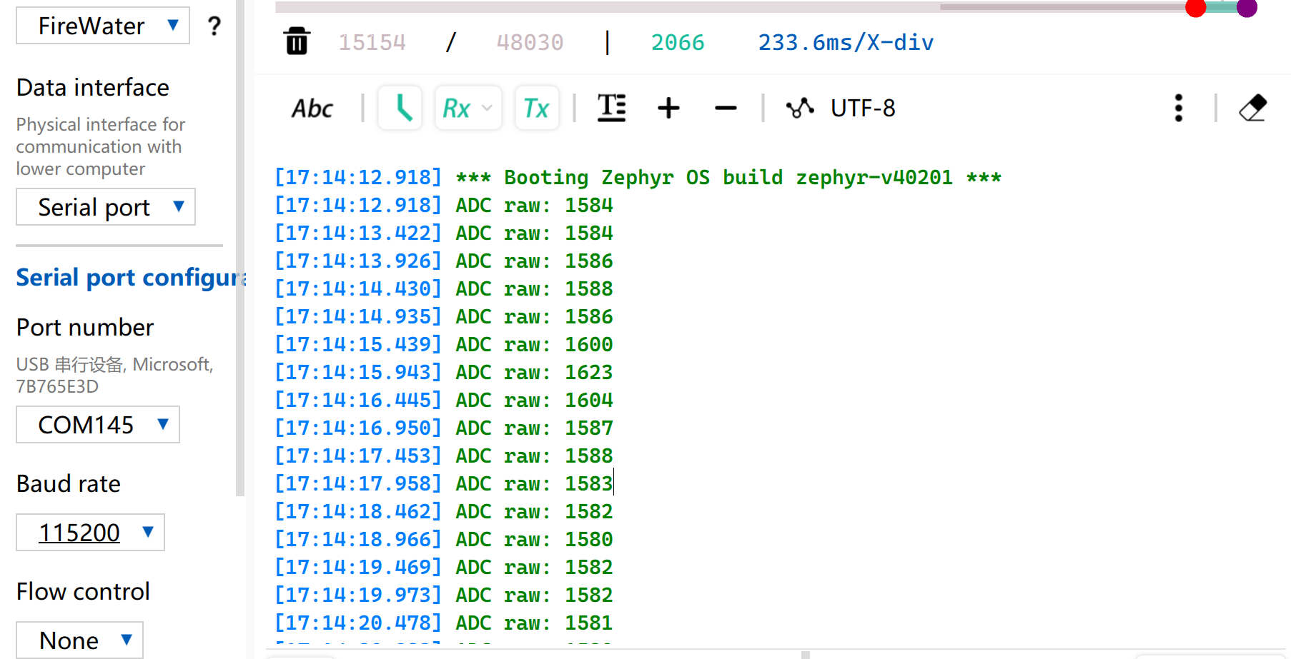
Tabela de leitura de referência de tensão
| Status | Tensão de saída do sensor | Valor bruto esperado do ADC |
|---|---|---|
| No ar (seco) | ~2,0–2,4V | ~3400–4095 |
| Em solo úmido | ~1,3–1,8V | ~2200–3000 |
| Totalmente imerso em água | ~0,8–1,2V | ~1365–2048 |
Devido a diferenças individuais nos componentes, medições de módulos diferentes no mesmo ambiente podem variar.
UART
O Universal Asynchronous Receiver/Transmitter (UART) é um protocolo padrão de comunicação serial assíncrona. Ele não requer sinais de clock externos para sincronização e realiza a transmissão e recepção assíncronas de dados com base na taxa de baud predefinida por ambos os lados da comunicação. Em termos de fiação física, um enlace de dados full-duplex pode ser estabelecido simplesmente conectando de forma cruzada os pinos TX e RX dos dispositivos e conectando seus terras em comum. Com custo de hardware mínimo e suporte para envio e recebimento simultâneos, o UART é amplamente adotado em sistemas embarcados para saída de logs de console, depuração de periféricos modulares e comunicação de dados ponto a ponto de baixa largura de banda.
Preparação de hardware
| Seeed Studio XIAO nRF54LM20A Sense | USB to TTL Converter |
|---|---|
 | |
Preparação de software
De acordo com o pinout do XIAO nRF54LM20A, P1.08 e P1.09 podem ser selecionados respectivamente como pinos TX e RX para comunicação serial.
- Para o pinout do XIAO nRF54LM20A, clique em XIAO nRF54LM20A Pin List para ver os detalhes.
- Modifique o arquivo da device tree, mapeie o pino P1.08 como UART TX e P1.09 como UART RX para o nó
uart21, e defina a taxa de baud da porta serial para 115200.
/*
 * UART21 Demo - Device Tree Overlay for XIAO nRF54LM20A
 * UART21: TX=P1.8, RX=P1.9
 *
 * Note: The pinctrl configuration is already defined in the board file.
 * This overlay enables UART21 and sets it as disabled for the default console
 * so it can be used as a general-purpose serial port.
 */

/* UART21 is already configured in the board dts, just make sure it's enabled */
&uart20 {
	current-speed = <115200>;
	status = "okay";
};

/* UART21 is already configured in the board dts, just make sure it's enabled */
&uart21 {
	current-speed = <115200>;
	status = "okay";
};
- Modifique o arquivo de configuração
prj.confpara habilitar as configurações UART relevantes.
# Serial and UART
CONFIG_SERIAL=y
# This demo uses uart_poll_in()/uart_poll_out().
# On nrfx UARTE, enabling async mode for the instance makes uart_poll_in()
# return -ENOTSUP, which breaks RX on uart21.

# Console (for logging via UART20)
CONFIG_CONSOLE=y
CONFIG_UART_CONSOLE=y

# Logging
CONFIG_LOG=y
CONFIG_LOG_BACKEND_UART=y
CONFIG_LOG_DEFAULT_LEVEL=3
- Escreva a função principal. Quando o botão BOOT on-board for pressionado, o status da porta serial e a configuração dos pinos serão impressos no computador via porta serial; caso contrário, o status de execução será impresso por padrão.
main.c
/*
 * UART21 Demo for XIAO nRF54LM20A (Polling Mode)
 *
 * This demo shows how to use UART21 for serial communication using polling mode.
 * - TX: P1.08
 * - RX: P1.09
 * - Baud rate: 115200
 *
 * The demo will:
 * 1. Send a welcome message on startup
 * 2. Echo back any received characters
 * 3. Periodically send a heartbeat message
 */

#include <zephyr/kernel.h>
#include <zephyr/device.h>
#include <zephyr/drivers/uart.h>
#include <zephyr/logging/log.h>
#include <stdio.h>
#include <string.h>

LOG_MODULE_REGISTER(uart21_demo, LOG_LEVEL_INF);

/* UART21 device */
static const struct device *uart21_dev = DEVICE_DT_GET(DT_NODELABEL(uart21));

#define RX_BUF_SIZE 128
#define TX_BUF_SIZE 256
#define HEARTBEAT_INTERVAL_MS 5000

static uint8_t rx_buf[RX_BUF_SIZE];
static size_t rx_buf_pos = 0;
static char tx_buf[TX_BUF_SIZE];

/* Send a string over UART21 using polling */
static void uart21_send_string(const char *str)
{
	while (*str)
	{
		uart_poll_out(uart21_dev, *str++);
	}
}

/* Receive a character from UART21 (non-blocking) */
static int uart21_recv_char(uint8_t *c)
{
	return uart_poll_in(uart21_dev, c);
}

static void handle_complete_line(void)
{
	rx_buf[rx_buf_pos] = '\0';

	if (rx_buf_pos > 0)
	{
		LOG_INF("Received: %s", rx_buf);
		uart21_send_string("\r\nYou sent: ");
		uart21_send_string((const char *)rx_buf);
	}

	uart21_send_string("\r\n");
	rx_buf_pos = 0;
	memset(rx_buf, 0, sizeof(rx_buf));
}

/* Process a received byte and maintain a simple line buffer */
static void process_rx_byte(uint8_t c)
{
	static bool last_was_cr;

	if (c == '\r' || c == '\n')
	{
		if (c == '\n' && last_was_cr)
		{
			last_was_cr = false;
			return;
		}

		uart21_send_string("\r\n");
		handle_complete_line();
		last_was_cr = (c == '\r');
		return;
	}

	last_was_cr = false;
	uart_poll_out(uart21_dev, c);

	if (rx_buf_pos < RX_BUF_SIZE - 1)
	{
		rx_buf[rx_buf_pos++] = c;
		return;
	}

	uart21_send_string("\r\n[Warning] Input too long, buffer cleared.\r\n");
	rx_buf_pos = 0;
	memset(rx_buf, 0, sizeof(rx_buf));
}

int main(void)
{
	uint8_t c;
	uint32_t heartbeat_count = 0;
	int64_t last_heartbeat = 0;

	LOG_INF("========================================");
	LOG_INF("  UART21 Demo for XIAO nRF54LM20A");
	LOG_INF("========================================");
	LOG_INF("");

	/* Check if UART21 device is ready */
	if (!device_is_ready(uart21_dev))
	{
		LOG_ERR("UART21 device not ready!");
		return -1;
	}
	LOG_INF("UART21 device ready: %s", uart21_dev->name);

	/* Send welcome message */
	uart21_send_string("\r\n");
	uart21_send_string("========================================\r\n");
	uart21_send_string("  UART21 Demo for XIAO nRF54LM20A\r\n");
	uart21_send_string("========================================\r\n");
	uart21_send_string("\r\n");
	uart21_send_string("Pin Configuration:\r\n");
	uart21_send_string("  TX: P1.08\r\n");
	uart21_send_string("  RX: P1.09\r\n");
	uart21_send_string("  Baud Rate: 115200\r\n");
	uart21_send_string("\r\n");
	uart21_send_string("Type something and press Enter to see it echoed.\r\n");
	uart21_send_string("\r\n");

	LOG_INF("UART21 demo started. Waiting for data...");
	LOG_INF("Connect UART terminal to P1.8(TX) and P1.9(RX)");

	last_heartbeat = k_uptime_get();

	/* Main loop */
	while (1)
	{
		/* Check for received data */
		if (uart21_recv_char(&c) == 0)
		{
			process_rx_byte(c);
		}

		/* Check for heartbeat */
		int64_t now = k_uptime_get();
		if (now - last_heartbeat >= HEARTBEAT_INTERVAL_MS)
		{
			last_heartbeat = now;
			heartbeat_count++;

			snprintf(tx_buf, sizeof(tx_buf),
					 "\r\n[Heartbeat #%u] UART21 running...\r\n",
					 heartbeat_count);
			uart21_send_string(tx_buf);

			LOG_INF("Heartbeat #%u sent", heartbeat_count);
		}

		/* Small delay to prevent busy loop */
		k_msleep(10);
	}

	return 0;
}
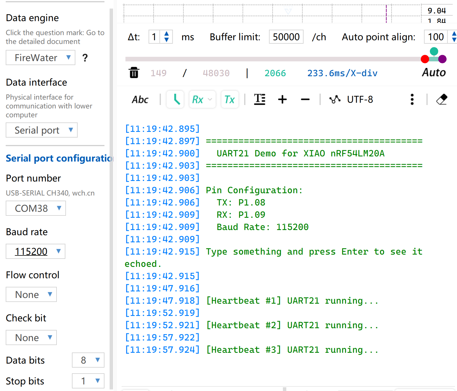
Resultado
- Faça a fiação de acordo com a ordem da tabela
| XIAO nRF54LM20A | CH340 |
|---|---|
| VBUS | 5V |
| GND | GND |
| P1.08 - TX | RX |
| P1.09 - RX | TX |
- Abra o software de monitoramento de porta serial no seu computador. Quando o botão BOOT on-board for pressionado, as informações configuradas da porta serial serão impressas via porta serial. Por padrão, a string
[Heartbeat # number] UART21 running...será impressa.
I2C
I2C é um protocolo de comunicação de dados síncrono e half-duplex. Ele permite a conexão de múltiplos dispositivos por meio de endereçamento através da linha de clock SCL e da linha de dados SDA, e é comumente usado para ler dados de sensores que exigem taxas de transmissão relativamente altas, como IMUs e sensores de temperatura/umidade, ou para saída de exibição em OLED.
Preparação de hardware
| Seeed Studio XIAO nRF54LM20A Sense | Placa de expansão Seeed Studio Base para XIAO |
|---|---|
 | |
Preparação de software
De acordo com o pinout do XIAO nRF54LM20A, P1.03 e P1.07 podem ser configurados como pinos I2C.
- Para o pinout do XIAO nRF54LM20A, clique em XIAO nRF54LM20A Pin List para ver os detalhes.
- Modifique a device tree, configure P1.03 e P1.07 no XIAO nRF54LM20A como os pinos do nó de device tree
i2c22, respectivamente, e então adicione o nó de device tree para o display. O display OLED possui resolução de 128×64 e adota o chip driver SSD1306 comum.
/ {
        chosen {
                zephyr,display = &ssd1306_128x64;
        };
};

&i2c22 {
        status = "okay";
        zephyr,concat-buf-size = <2048>;
        ssd1306_128x64: ssd1306@3c {
                compatible = "solomon,ssd1306fb";
                reg = <0x3c>;
                width = <128>;
                height = <64>;
                segment-offset = <0>;
                page-offset = <0>;
                display-offset = <0>;
                multiplex-ratio = <63>;
                segment-remap;
                com-invdir;
                prechargep = <0x22>;
        };
};
- Modifique o arquivo
prj.confpara habilitar as configurações relacionadas a I2C e display.
CONFIG_STDOUT_CONSOLE=y
CONFIG_HEAP_MEM_POOL_SIZE=16384
CONFIG_I2C=y
CONFIG_DISPLAY=y
CONFIG_SSD1306=y
CONFIG_LOG=y
CONFIG_LOG_DEFAULT_LEVEL=4
CONFIG_CHARACTER_FRAMEBUFFER=y
- Escreva a função principal para definir a posição de exibição e as funções para a string.
main.c
#include <zephyr/kernel.h>
#include <zephyr/device.h>
#include <zephyr/display/cfb.h>
#include <stdio.h>
#include <string.h>
#define LOG_LEVEL CONFIG_LOG_DEFAULT_LEVEL
#include <zephyr/logging/log.h>
LOG_MODULE_REGISTER(main_app, LOG_LEVEL);
#define CFB_MAX_FONT_INDEX 42
/* Display content */
#define LINE1_TEXT "Hello XIAO"
#define LINE2_TEXT "nRF54LM20A"
#define TOTAL_LINES 2
static int display_init(const struct device **dev) {
*dev = DEVICE_DT_GET(DT_CHOSEN(zephyr_display));
if (!device_is_ready(*dev)) {
LOG_ERR("Device %s not ready", (*dev)->name);
return -1;
}
if (display_set_pixel_format(*dev, PIXEL_FORMAT_MONO10) != 0) {
if (display_set_pixel_format(*dev, PIXEL_FORMAT_MONO01) != 0) {
LOG_ERR("Failed to set required pixel format");
return -1;
}
}
LOG_INF("Initialized %s", (*dev)->name);
return 0;
}
static int framebuffer_setup(const struct device *dev) {
if (cfb_framebuffer_init(dev)) {
LOG_ERR("Framebuffer initialization failed!");
return -1;
}
cfb_framebuffer_clear(dev, false);
display_blanking_off(dev);
return 0;
}
static int select_font(const struct device *dev, uint8_t *font_width, uint8_t *font_height) {
int chosen_font_idx = -1;
uint8_t current_font_width, current_font_height;
for (int idx = 0; idx < CFB_MAX_FONT_INDEX; idx++) {
if (cfb_get_font_size(dev, idx, ¤t_font_width, ¤t_font_height) != 0) {
continue;
}
if (current_font_width == 0 || current_font_height == 0) {
continue;
}
if (current_font_width == 8 && current_font_height == 8) {
chosen_font_idx = idx;
*font_width = current_font_width;
*font_height = current_font_height;
cfb_framebuffer_set_font(dev, chosen_font_idx);
LOG_INF("Selected 8x8 font idx: %d", chosen_font_idx);
break;
}
if (chosen_font_idx == -1) {
chosen_font_idx = idx;
*font_width = current_font_width;
*font_height = current_font_height;
cfb_framebuffer_set_font(dev, chosen_font_idx);
LOG_INF("Fallback font idx: %d, size: %dx%d",
chosen_font_idx, *font_width, *font_height);
}
}
if (chosen_font_idx == -1) {
LOG_ERR("No suitable font found!");
return -1;
}
return 0;
}
/**
* @brief Print a line of text centered on the display
* @param dev Display device
* @param text String to be printed
* @param line_index Index of current line (0-indexed)
* @param total_lines Total number of lines (for vertical centering calculation)
* @param font_width Font width in pixels
* @param font_height Font height in pixels
* @param x_res Horizontal resolution of the display
* @param y_res Vertical resolution of the display
*/
static void print_text_centered(const struct device *dev,
const char *text,
int line_index,
int total_lines,
uint8_t font_width,
uint8_t font_height,
uint16_t x_res,
uint16_t y_res)
{
int text_len = (int)strlen(text);
/* Horizontal center: (screen width - total text pixel width) / 2 */
int pixel_x = (x_res - text_len * font_width) / 2;
/* Vertical center: calculate total block height first, then offset current line */
int block_height = total_lines * font_height;
int pixel_y = (y_res - block_height) / 2 + line_index * font_height;
/* Prevent coordinate out-of-bounds */
if (pixel_x < 0) pixel_x = 0;
if (pixel_y < 0) pixel_y = 0;
if (cfb_print(dev, text, pixel_x, pixel_y)) {
LOG_ERR("Failed to print \"%s\" at (%d, %d)", text, pixel_x, pixel_y);
}
LOG_DBG("Print \"%s\" at pixel (%d, %d)", text, pixel_x, pixel_y);
}
int main(void) {
const struct device *dev;
uint8_t font_width = 0;
uint8_t font_height = 0;
if (display_init(&dev) != 0) return 0;
if (framebuffer_setup(dev) != 0) return 0;
if (select_font(dev, &font_width, &font_height) != 0) return 0;
uint16_t x_res = cfb_get_display_parameter(dev, CFB_DISPLAY_WIDTH);
uint16_t y_res = cfb_get_display_parameter(dev, CFB_DISPLAY_HEIGHT);
LOG_INF("Display resolution: %dx%d", x_res, y_res);
cfb_set_kerning(dev, 0);
while (1) {
cfb_framebuffer_clear(dev, false);
print_text_centered(dev, LINE1_TEXT, 0, TOTAL_LINES,
font_width, font_height, x_res, y_res);
print_text_centered(dev, LINE2_TEXT, 1, TOTAL_LINES,
font_width, font_height, x_res, y_res);
cfb_framebuffer_finalize(dev);
k_sleep(K_MSEC(1000));
}
return 0;
}
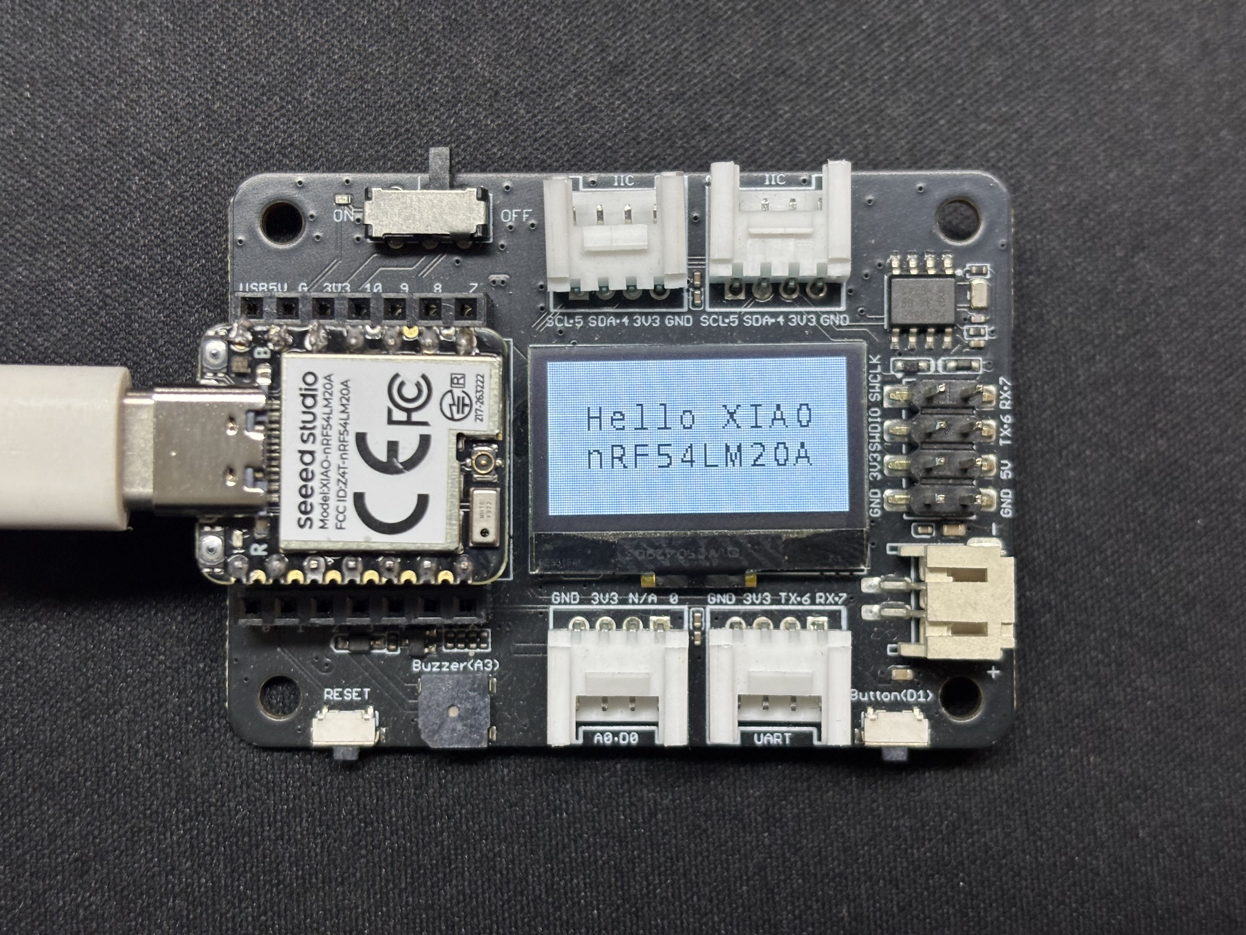
Resultado
Após a execução do programa, o texto Hello XIAO nRF54LM20A será exibido na tela, e os dados da thread serão impressos pela porta serial USB.
SPI
SPI é um protocolo de comunicação síncrono, full-duplex e de alta velocidade. Diferente da comunicação assíncrona, o SPI depende de uma linha de clock SCLK dedicada para sincronização precisa dos dados. Geralmente, adota a topologia clássica de hardware de quatro fios, composta pelos pinos MOSI, MISO e de seleção de chip CS/SS. Equipado com canais independentes de envio e recebimento de dados e alta frequência de clock de barramento, o SPI oferece excelente taxa de transferência de dados. É amplamente utilizado em cenários de acionamento de periféricos que exigem alta largura de banda, como dispositivos de armazenamento em massa, incluindo memórias Flash e cartões SD, telas de alta resolução e alta taxa de atualização e sensores de amostragem em alta frequência.
Preparação de hardware
| Seeed Studio XIAO nRF54LM20A Sense | Round Display para Seeed Studio XIAO |
|---|---|
 | |
Preparação de software
- Para o pinout do XIAO nRF54LM20A, clique em XIAO nRF54LM20A Pin List para ver os detalhes.
- Modifique o arquivo da árvore de dispositivo. Para acionar a tela LCD, habilite o nó spi23 e configure o mapeamento de pinos na árvore de dispositivo. Defina P1.04, P1.05 e P1.06 como SCK, MISO e MOSI do SPI, respectivamente. Ao mesmo tempo, configure P1.31 e P1.29 como os pinos de controle CS (Chip Select) e DC (Data/Command) da tela.
app.overlay
#include <dt-bindings/pinctrl/nrf-pinctrl.h>
#include <zephyr/dt-bindings/gpio/gpio.h>
#include <zephyr/dt-bindings/display/panel.h>

/*
 * GC9X01X 240x240 round LCD configuration for XIAO nRF54LM20A
 * SPI23:  SCK=P1.04  MOSI=P1.06  MISO=P1.05
 * CS:     P1.31  (SPI bus software CS)
 * DC:     P1.29  (Data/Command select, on MIPI DBI node)
 *
 * In Zephyr 4.x the GC9X01X driver uses the MIPI DBI interface.
 * The display node must be a child of a zephyr,mipi-dbi-spi node,
 * which references the SPI controller via spi-dev phandle.
 */

/ {
    chosen {
        zephyr,console    = &uart20;
        nordic,rpc-uart   = &uart20;
        zephyr,shell-uart = &uart20;
        zephyr,display    = &gc9x01x;
    };

    mipi_dbi {
        compatible = "zephyr,mipi-dbi-spi";
        spi-dev = <&spi23>;
        dc-gpios = <&gpio1 29 GPIO_ACTIVE_HIGH>;
        write-only;
        #address-cells = <1>;
        #size-cells = <0>;

        gc9x01x: gc9x01x@0 {
            compatible = "galaxycore,gc9x01x";
            reg = <0>;
            mipi-max-frequency = <40000000>;
            pixel-format = <PANEL_PIXEL_FORMAT_RGB_565>;
            display-inversion;
            width  = <240>;
            height = <240>;
            status = "okay";
        };
    };
};

&spi23 {
    compatible = "nordic,nrf-spim";
    pinctrl-names = "default", "sleep";
    pinctrl-0 = <&spi23_default>;
    pinctrl-1 = <&spi23_sleep>;
    status = "okay";

    /* CS P1.31 — index 0 used by the MIPI DBI driver */
    cs-gpios = <&gpio1 31 GPIO_ACTIVE_LOW>;
};

&uart20 {
    status = "okay";
};

&pinctrl {
    spi23_default: spi23_default {
        group1 {
            psels = <NRF_PSEL(SPIM_SCK,  1, 4)>,
                    <NRF_PSEL(SPIM_MOSI, 1, 6)>;
        };
        group2 {
            psels = <NRF_PSEL(SPIM_MISO, 1, 5)>;
            bias-pull-up;
        };
    };

    spi23_sleep: spi23_sleep {
        group1 {
            psels = <NRF_PSEL(SPIM_SCK,  1, 4)>,
                    <NRF_PSEL(SPIM_MOSI, 1, 6)>,
                    <NRF_PSEL(SPIM_MISO, 1, 5)>;
            low-power-enable;
        };
    };
};

&uart20_default {
    /delete-node/ group1;
    /delete-node/ group2;

    group1 {
        psels = <NRF_PSEL(UART_TX, 1, 11)>;
    };
    group2 {
        psels = <NRF_PSEL(UART_RX, 1, 10)>;
        bias-pull-up;
    };
};

&uart20_sleep {
    /delete-node/ group1;

    group1 {
        psels = <NRF_PSEL(UART_TX, 1, 11)>,
                <NRF_PSEL(UART_RX, 1, 10)>;
        low-power-enable;
    };
};
- Modifique o prj.conf para ativar as configurações relacionadas a SPI.
CONFIG_LOG=y
CONFIG_LOG_DEFAULT_LEVEL=3
CONFIG_CONSOLE=y
CONFIG_UART_CONSOLE=y
CONFIG_GPIO=y
CONFIG_SPI=y
CONFIG_DISPLAY=y
CONFIG_CHARACTER_FRAMEBUFFER=y
CONFIG_CHARACTER_FRAMEBUFFER_USE_DEFAULT_FONTS=y
CONFIG_HEAP_MEM_POOL_SIZE=32768
CONFIG_MAIN_STACK_SIZE=4096
- Modifique o programa main.c e escreva a lógica de preenchimento de tela com cor sólida.
main.c
#include <zephyr/kernel.h>
#include <zephyr/device.h>
#include <zephyr/display/cfb.h>
#include <zephyr/drivers/display.h>
#include <string.h>
#include <stdlib.h>

#define LOG_LEVEL CONFIG_LOG_DEFAULT_LEVEL
#include <zephyr/logging/log.h>
LOG_MODULE_REGISTER(gc9a01_demo, LOG_LEVEL);

/* GC9A01 Resolution */
#define LCD_W  240
#define LCD_H  240

/* RGB565 Color Definitions */
#define COLOR_BLACK   0x0000U
#define COLOR_WHITE   0xFFFFU
#define COLOR_RED     0xF800U
#define COLOR_GREEN   0x07E0U
#define COLOR_BLUE    0x001FU
#define COLOR_YELLOW  0xFFE0U
#define COLOR_CYAN    0x07FFU
#define COLOR_MAGENTA 0xF81FU
#define COLOR_ORANGE  0xFD20U

/* -------------------------------------------------------
 * Low-level: Fill entire screen using display_write
 * buf: RGB565 pixel buffer, length = w * h * 2 bytes
 * ------------------------------------------------------- */
static uint16_t fb[LCD_W * LCD_H];   /* ~115 KB, declared globally to avoid stack overflow */

static void fill_screen(const struct device *dev, uint16_t color)
{
    /* RGB565 Big-endian (Default for GC9A01) */
    uint16_t be = (color >> 8) | (color << 8);
    for (int i = 0; i < LCD_W * LCD_H; i++) {
        fb[i] = be;
    }

    struct display_buffer_descriptor desc = {
        .buf_size = sizeof(fb),
        .width    = LCD_W,
        .height   = LCD_H,
        .pitch    = LCD_W,
    };
    display_write(dev, 0, 0, &desc, fb);
}

/* -------------------------------------------------------
 * Scene 1: Solid color full-screen fill, cycle colors
 * ------------------------------------------------------- */
static void demo_solid_colors(const struct device *dev)
{
    static const uint16_t colors[] = {
        COLOR_RED, COLOR_GREEN, COLOR_BLUE,
        COLOR_YELLOW, COLOR_CYAN, COLOR_MAGENTA,
    };
    static const char *names[] = {
        "RED", "GREEN", "BLUE", "YELLOW", "CYAN", "MAGENTA",
    };

    for (int i = 0; i < ARRAY_SIZE(colors); i++) {
        LOG_INF("Solid: %s", names[i]);
        fill_screen(dev, colors[i]);
        k_sleep(K_MSEC(600));
    }
}

/* -------------------------------------------------------
 * Scene 2: Color vertical bars (6 bars, 40px width each)
 * ------------------------------------------------------- */
static void demo_color_bars(const struct device *dev)
{
    static const uint16_t bar_colors[] = {
        COLOR_RED, COLOR_ORANGE, COLOR_YELLOW,
        COLOR_GREEN, COLOR_BLUE, COLOR_MAGENTA,
    };
    static const int BAR_W = LCD_W / ARRAY_SIZE(bar_colors);  /* = 40 */

    for (int y = 0; y < LCD_H; y++) {
        for (int x = 0; x < LCD_W; x++) {
            uint16_t c = bar_colors[x / BAR_W];
            uint16_t be = (c >> 8) | (c << 8);
            fb[y * LCD_W + x] = be;
        }
    }

    struct display_buffer_descriptor desc = {
        .buf_size = sizeof(fb),
        .width    = LCD_W,
        .height   = LCD_H,
        .pitch    = LCD_W,
    };
    display_write(dev, 0, 0, &desc, fb);
    LOG_INF("Color bars");
    k_sleep(K_MSEC(2000));
}

/* -------------------------------------------------------
 * Main Application
 * ------------------------------------------------------- */
int main(void)
{
    LOG_INF("GC9A01 demo — XIAO nRF54LM20A");

    const struct device *dev = DEVICE_DT_GET(DT_CHOSEN(zephyr_display));
    if (!device_is_ready(dev)) {
        LOG_ERR("Display device not ready");
        return 0;
    }

    /* Set pixel format: GC9A01 uses RGB565 */
    if (display_set_pixel_format(dev, PIXEL_FORMAT_RGB_565) != 0) {
        LOG_ERR("Failed to set pixel format");
        return 0;
    }

    display_blanking_off(dev);
    LOG_INF("Display ready, starting demo loop");

    while (1) {
        demo_solid_colors(dev);   /* 6-color cycle ~3.6s */
        demo_color_bars(dev);     /* Color vertical bars ~2s */
    }

    return 0;
}
Resultado
Após ligar, o programa atualiza a tela na sequência vermelho, laranja, amarelo, verde, ciano, azul e roxo e, por fim, exibe padrões coloridos em listras.
Suporte Técnico e Discussão de Produtos
Obrigado por escolher nossos produtos! Estamos aqui para fornecer diferentes tipos de suporte para garantir que sua experiência com nossos produtos seja a mais tranquila possível. Oferecemos vários canais de comunicação para atender a diferentes preferências e necessidades.