Uso dos sensores integrados do XIAO nRF54LM20A Sense

O XIAO nRF54LM20A Sense está equipado com abundantes sensores integrados para suportar aplicações em múltiplos cenários. Ele inclui o sensor de seis eixos LSM6DS3TR-C para reconhecimento de postura e o microfone digital MEMS MSM261DGT006, que suporta saída digital PDM e captação de som omnidirecional, sendo adequado para cenários de voz inteligente. Este artigo apresenta os métodos de desenvolvimento e uso com base nos ricos periféricos integrados do XIAO nRF54LM20A.
- Este artigo é desenvolvido com base no sistema de build PlatformIO e no Zephyr RTOS. Se você não tiver experiência prévia com eles, consulte Getting Started With SeeedStudio XIAO nRF54LM20A
Preparação de hardware
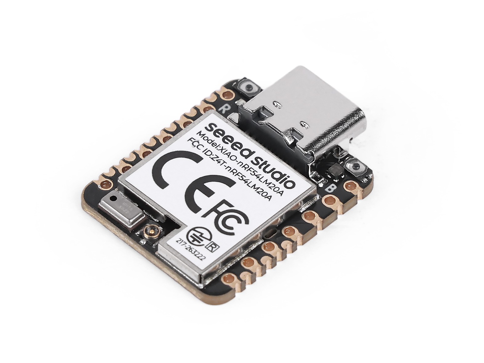
Este artigo é desenvolvido com base no XIAO nRF54LM20A Sense, e você precisa preparar o hardware relevante com antecedência.
| Seeed Studio XIAO nRF54LM20A Sense | Matriz RGB WS2812 6x10 para Seeed Studio XIAO |
|---|---|
 |  |
IMU
O LSM6DS3TR-C é um sensor de seis eixos que integra um acelerômetro digital de 3 eixos e um giroscópio digital de 3 eixos, pertencente à unidade de medição inercial (IMU) iNEMO lançada pela STMicroelectronics. No XIAO nRF54LM20A Sense, esse sensor suporta saída de dados acionada por interrupção. Ele possui uma faixa de aceleração de escala completa de ±2/±4/±8/±16 g e uma faixa de velocidade angular de ±125/±250/±500/±1000/±2000 dps, além de suportar modo de baixo consumo persistente, tornando-o adequado para vários cenários de detecção de movimento. O chip integrado se comunica com ele por meio do protocolo I2C para adquirir dados.
- Para mais informações sobre o LSM6DS3TR-C, visite: Product overview for LSM6DS3TR-C e LSM6DS3TR-C Datasheet
Obter dados de seis eixos
- Modifique o arquivo de device tree
app.overlaypara vincular os pinos de hardware usados pelo LSM6DS3TR-C à device tree. Vincule IMU_SDA e IMU_SCL ao nó i2c30, correspondendo a P0.08 e P0.07 no XIAO nRF54LM20A Sense. Vincule o pino de disparo de interrupção IMU_INT1 a P0.06.
- Para o pinout do XIAO nRF54LM20A, clique em XIAO nRF54LM20A Sense Pin List para ver os detalhes.
&pmic_i2c {
        sda-gpios = <&gpio1 18 GPIO_ACTIVE_HIGH>;
        scl-gpios = <&gpio1 17 GPIO_ACTIVE_HIGH>;
        status = "okay";
};

&pmic {
        regulators {
                imu_vdd: LDO1 {
                        regulator-min-microvolt = <3300000>;
                        regulator-max-microvolt = <3300000>;
                        /*
                         * Do not enable LDO1 during regulator driver init: the
                         * nPM1300 sits on gpio-i2c, which may not be ready yet.
                         * main() enables this rail before deferred IMU init.
                         * Use /delete-property/ so this also overrides board
                         * revisions that define regulator-boot-on themselves.
                         */
                        /delete-property/ regulator-boot-on;
                };
        };
};

&lsm6ds3tr_c {
        zephyr,deferred-init;
};
- Modifique o arquivo prj.conf para habilitar as configurações de I2C e de disparo por interrupção.
CONFIG_STDOUT_CONSOLE=y

CONFIG_LOG=y
CONFIG_LOG_BACKEND_UART=y
CONFIG_LOG_BACKEND_SHOW_COLOR=n
CONFIG_LOG_DEFAULT_LEVEL=3
CONFIG_MAIN_STACK_SIZE=2048
CONFIG_SYSTEM_WORKQUEUE_STACK_SIZE=2048
CONFIG_GPIO=y
CONFIG_I2C=y
CONFIG_MFD=y
CONFIG_REGULATOR=y
CONFIG_SENSOR=y
CONFIG_LSM6DSL=y
CONFIG_LSM6DSL_TRIGGER_GLOBAL_THREAD=y
CONFIG_CBPRINTF_FP_SUPPORT=y
CONFIG_CBPRINTF_COMPLETE=y
- Escreva um programa para enviar os dados adquiridos do acelerômetro digital de 3 eixos e do giroscópio digital de 3 eixos pela porta serial USB.
main.c
#include <errno.h>
#include <zephyr/kernel.h>
#include <zephyr/device.h>
#include <zephyr/drivers/sensor.h>
#include <zephyr/drivers/regulator.h>
#include <zephyr/logging/log.h>

LOG_MODULE_REGISTER(zephyr_imu, LOG_LEVEL_INF);

#define IMU_NODE DT_ALIAS(imu0)

/*
 * nrf54lm20a needs power_en (fixed regulator on gpio1.12) and imu_vdd
 * (PMIC NPM1300 LDO1) enabled before the IMU can be used.
 * nrf54l15 has pdm_imu_pwr with regulator-boot-on; power is already on.
 */
#if defined(DT_N_NODELABEL_power_en)
static const struct device *const power_en_dev =
    DEVICE_DT_GET(DT_NODELABEL(power_en));
#endif

#if defined(DT_N_NODELABEL_imu_vdd)
static const struct device *const imu_vdd_dev =
    DEVICE_DT_GET(DT_NODELABEL(imu_vdd));
#endif

static int enable_imu_power(void)
{
#if defined(DT_N_NODELABEL_power_en) || defined(DT_N_NODELABEL_imu_vdd)
    int ret;
#endif

#if defined(DT_N_NODELABEL_power_en)
    if (!device_is_ready(power_en_dev)) {
        LOG_ERR("power_en regulator is not ready");
        return -ENODEV;
    }
    ret = regulator_enable(power_en_dev);
    if (ret < 0 && ret != -EALREADY) {
        LOG_ERR("Failed to enable power_en: %d", ret);
        return ret;
    }
#endif

#if defined(DT_N_NODELABEL_imu_vdd)
    if (!device_is_ready(imu_vdd_dev)) {
        LOG_ERR("imu_vdd regulator is not ready");
        return -ENODEV;
    }
    ret = regulator_enable(imu_vdd_dev);
    if (ret < 0 && ret != -EALREADY) {
        LOG_ERR("Failed to enable imu_vdd: %d", ret);
        return ret;
    }
#endif

#if defined(DT_N_NODELABEL_power_en) || defined(DT_N_NODELABEL_imu_vdd)
    /* Wait for power rail to stabilize */
    k_sleep(K_MSEC(20));
#endif

    return 0;
}

static inline float out_ev(struct sensor_value *val)
{
    return (val->val1 + (float)val->val2 / 1000000);
}

static void fetch_and_display(const struct device *dev)
{
    struct sensor_value x, y, z;
    static int trig_cnt;

    trig_cnt++;

    /* lsm6dsl accel */
    sensor_sample_fetch_chan(dev, SENSOR_CHAN_ACCEL_XYZ);
    sensor_channel_get(dev, SENSOR_CHAN_ACCEL_X, &x);
    sensor_channel_get(dev, SENSOR_CHAN_ACCEL_Y, &y);
    sensor_channel_get(dev, SENSOR_CHAN_ACCEL_Z, &z);

    LOG_INF("accel x:%f m/s^2 y:%f m/s^2 z:%f m/s^2",
            (double)out_ev(&x), (double)out_ev(&y), (double)out_ev(&z));

    /* lsm6dsl gyro */
    sensor_sample_fetch_chan(dev, SENSOR_CHAN_GYRO_XYZ);
    sensor_channel_get(dev, SENSOR_CHAN_GYRO_X, &x);
    sensor_channel_get(dev, SENSOR_CHAN_GYRO_Y, &y);
    sensor_channel_get(dev, SENSOR_CHAN_GYRO_Z, &z);

    LOG_INF("gyro x:%f rad/s y:%f rad/s z:%f rad/s",
            (double)out_ev(&x), (double)out_ev(&y), (double)out_ev(&z));

    LOG_INF("trig_cnt:%d", trig_cnt);
}

static int set_sampling_freq(const struct device *dev)
{
    int ret = 0;
    struct sensor_value odr_attr;

    /* set accel/gyro sampling frequency to 12.5 Hz */
    odr_attr.val1 = 12;
    odr_attr.val2 = 500000;

    ret = sensor_attr_set(dev, SENSOR_CHAN_ACCEL_XYZ,
            SENSOR_ATTR_SAMPLING_FREQUENCY, &odr_attr);
    if (ret != 0) {
        LOG_ERR("Cannot set sampling frequency for accelerometer.");
        return ret;
    }

    ret = sensor_attr_set(dev, SENSOR_CHAN_GYRO_XYZ,
            SENSOR_ATTR_SAMPLING_FREQUENCY, &odr_attr);
    if (ret != 0) {
        LOG_ERR("Cannot set sampling frequency for gyro.");
        return ret;
    }

    return 0;
}

#ifdef CONFIG_LSM6DSL_TRIGGER
static void trigger_handler(const struct device *dev,
                const struct sensor_trigger *trig)
{
    fetch_and_display(dev);
}

static void test_trigger_mode(const struct device *dev)
{
    struct sensor_trigger trig;

    if (set_sampling_freq(dev) != 0) {
        return;
    }

    trig.type = SENSOR_TRIG_DATA_READY;
    trig.chan = SENSOR_CHAN_ACCEL_XYZ;

    if (sensor_trigger_set(dev, &trig, trigger_handler) != 0) {
        LOG_ERR("Could not set sensor type and channel");
        return;
    }

    while (1) {
        k_sleep(K_MSEC(1000));
    }
}

#else
static void test_polling_mode(const struct device *dev)
{
    if (set_sampling_freq(dev) != 0) {
        return;
    }

    while (1) {
        fetch_and_display(dev);
        k_sleep(K_MSEC(1000));
    }
}
#endif

int main(void)
{
    const struct device *const dev = DEVICE_DT_GET(IMU_NODE);
    int ret;

    /* On nrf54lm20a, enable power_en + imu_vdd before accessing IMU.
     * On nrf54l15, these nodes don't exist; function returns immediately.
     */
    ret = enable_imu_power();
    if (ret < 0) {
        LOG_ERR("Failed to enable IMU power: %d", ret);
        return 0;
    }

    /* On nrf54lm20a, IMU has zephyr,deferred-init; must init manually.
     * On nrf54l15, device auto-inits at boot; device_is_ready() is true.
     */
    if (!device_is_ready(dev)) {
        ret = device_init(dev);
        if (ret < 0 && ret != -EALREADY) {
            LOG_ERR("Failed to initialize %s: %d", dev->name, ret);
            return 0;
        }
    }

    if (!device_is_ready(dev)) {
        LOG_ERR("%s: device not ready.", dev->name);
        return 0;
    }

#ifdef CONFIG_LSM6DSL_TRIGGER
    LOG_INF("Testing LSM6DSL sensor in trigger mode.");
    test_trigger_mode(dev);
#else
    LOG_INF("Testing LSM6DSL sensor in polling mode.");
    test_polling_mode(dev);
#endif
    return 0;
}
Se você quiser verificar diretamente o desempenho do IMU, clone o repositório Platform-seeedboards, localize o exemplo zephyr-imu no diretório examples, depois compile e grave o programa para iniciar o teste.
Resultado
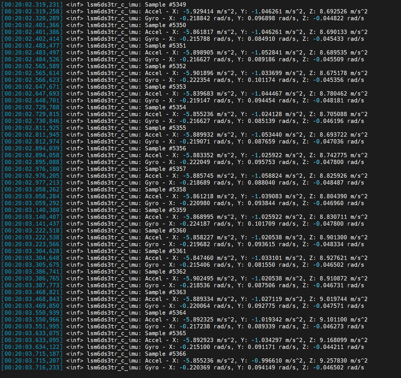
Após gravar o firmware, você pode abrir o assistente de porta serial no seu PC para visualização dos dados. A frequência de disparo é de 12,5 Hz com um intervalo de 80 milissegundos.
- Acelerômetro digital de 3 eixos: Mede a aceleração ao longo dos eixos X, Y e Z.
- Giroscópio digital de 3 eixos: Mede a velocidade angular em torno dos eixos X, Y e Z.
- Defina a taxa de transmissão para 115200 ao visualizar dados via monitor serial.
- Especifique a taxa de transmissão como 115200 no arquivo de configuração platformio.ini para o monitor serial da IDE PlatformIO.
[env:seeed-xiao-nrf54lm20a]
platform = https://github.com/Seeed-Studio/platform-seeedboards.git
framework = zephyr
board = seeed-xiao-nrf54lm20a
monitor_speed = 115200
Aplicação
O IMU pode fundir dados de aceleração de três eixos para calcular os ângulos de atitude de pitch, yaw e roll para reconhecimento de postura. Ele também pode trabalhar com controladores correspondentes para realizar controle de movimento, ou ser aplicado em cenários de baixo consumo de energia, como despertar acionado por atitude.
Oceano Eletrônico
Este é um exemplo baseado no IMU integrado do XIAO nRF54LM20A Sense. Ele coleta dados de atitude e funde informações de aceleração para mapear estados de movimento no painel de luz RGB, alcançando efeitos visuais de ritmo oceânico.
- Controle de nível de água por inclinação — Ajuste a altura do nível de água por meio da inclinação de roll para a esquerda e para a direita
- Animação de ondas — Superfície de ondas com sobreposição de três camadas de frequência, propagação de ondas 2D e efeito de reflexão nas bordas
- Inércia do fluido — Superfície de água com momento; inclinação rápida causa overshoot e subsequente oscilação de retorno
- Detecção de inversão — A exibição é espelhada automaticamente quando a placa é virada
- Cor dinâmica — Troca de tons oceânicos em gradiente aleatório para cada coluna
Além disso, você pode modificar a configuração da matriz RGB da placa por meio de definições de macro em main.c.
#define COLS 10          // Number of matrix columns
#define ROWS  6          // Number of matrix rows
#define BRIGHTNESS 5     // Overall brightness (0-100)
#define WATER_CENTER 3.5f // Water level when placed horizontally
#define WATER_MIN 0.5f   // Minimum water level
#define WATER_MAX 6.5f   // Maximum water level
Instruções de uso
-
Copie o conteúdo do programa correspondente imu_ocean-main.c e cole em main.c.
-
Modifique o arquivo de árvore de dispositivo
app.overlay.
&lsm6ds3tr_c {
	zephyr,deferred-init;
};

/*
 * The board DTS lists PMIC I2C on gpio1.15/16, but the actual XIAO
 * nRF54LM20A Sense hardware uses gpio1.18 (SDA) and gpio1.17 (SCL).
 * Override here to match the working reference example.
 */
&pmic_i2c {
	sda-gpios = <&gpio1 18 GPIO_ACTIVE_HIGH>;
	scl-gpios = <&gpio1 17 GPIO_ACTIVE_HIGH>;
};

/*
 * Give LDO1 the label "imu_vdd" so main() can call regulator_enable().
 * Voltage is 3.3 V as used by the reference example.
 */
&pmic {
	regulators {
		imu_vdd: LDO1 {
			regulator-min-microvolt = <3300000>;
			regulator-max-microvolt = <3300000>;
			regulator-boot-on;
		};
	};
};

/* WS2812 LED strip on SPI24 (spi21/22 conflict with uart21/i2c22) */
&pinctrl {
	spi24_ws2812_default: spi24_ws2812_default {
		group1 {
			psels = <NRF_PSEL(SPIM_MOSI, 1, 0)>,
				<NRF_PSEL(SPIM_SCK, 1, 1)>;
		};
	};

	spi24_ws2812_sleep: spi24_ws2812_sleep {
		group1 {
			psels = <NRF_PSEL(SPIM_MOSI, 1, 0)>,
				<NRF_PSEL(SPIM_SCK, 1, 1)>;
			low-power-enable;
		};
	};
};


&spi24 {
	status = "okay";
	pinctrl-0 = <&spi24_ws2812_default>;
	pinctrl-1 = <&spi24_ws2812_sleep>;
	pinctrl-names = "default", "sleep";

	led_strip: ws2812@0 {
		compatible = "worldsemi,ws2812-spi";
		reg = <0>;
		/*
		 * 8 MHz SPI: each clock = 125 ns, 8 clocks = 1 µs per WS2812 bit.
		 * 0xF8 = 11111000: T1H=625 ns  T1L=375 ns
		 * 0xC0 = 11000000: T0H=250 ns  T0L=750 ns
		 */
		spi-max-frequency = <8000000>;
		spi-one-frame  = <0xF8>;
		spi-zero-frame = <0xC0>;
		chain-length = <60>;
		color-mapping = <1 0 2>;
		reset-delay = <250>;
	};
};

/ {
	aliases {
		led-strip = &led_strip;
	};
};
- Ative as configurações relacionadas ao uso do IMU
CONFIG_STDOUT_CONSOLE=y
CONFIG_LOG=y
CONFIG_LOG_BACKEND_UART=y
CONFIG_LOG_DEFAULT_LEVEL=3
CONFIG_MAIN_STACK_SIZE=4096
CONFIG_SYSTEM_WORKQUEUE_STACK_SIZE=2048
CONFIG_GPIO=y
CONFIG_I2C=y
CONFIG_MFD=y
CONFIG_REGULATOR=y
CONFIG_SENSOR=y
CONFIG_LSM6DSL=y
CONFIG_SPI=y
CONFIG_LED_STRIP=y
CONFIG_WS2812_STRIP_SPI=y
CONFIG_CBPRINTF_FP_SUPPORT=y
CONFIG_CBPRINTF_COMPLETE=y
CONFIG_FAULT_DUMP=2
CONFIG_LOG_MODE_IMMEDIATE=y
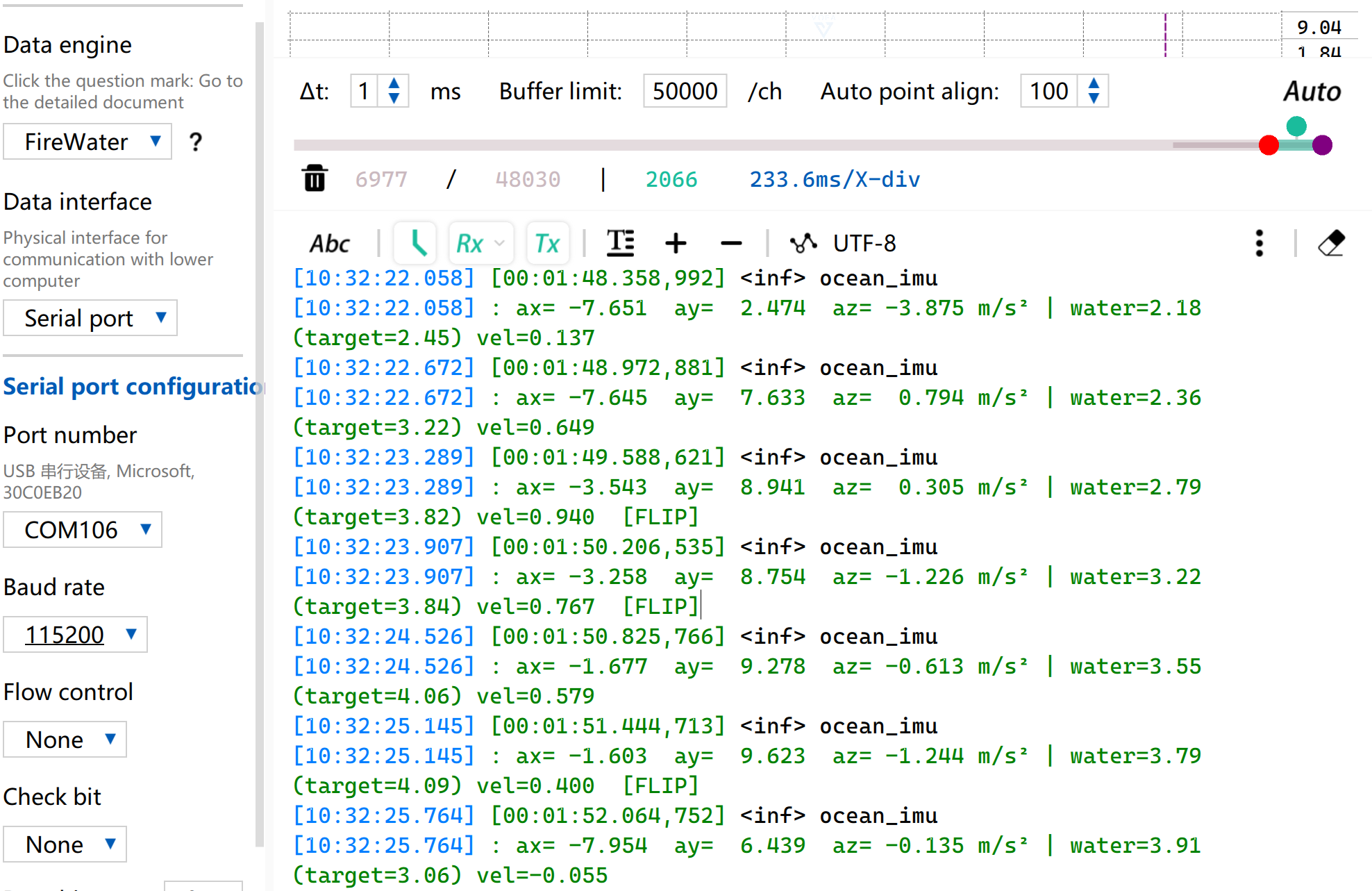
- Agite o dispositivo para acionar o efeito visual de ondas do oceano.
- Ao mesmo tempo, a porta serial também irá exibir os dados correspondentes do IMU e a altura atual do nível de água das ondas.
Despertar por IMU
Nesta rotina, o canal verde do RGB acende e apaga após a energização, e então o sistema entra em modo de sono de ultrabaixo consumo. Quando um toque é detectado pela placa, o XIAO nRF54LM20A Sense será despertado via interrupção. O evento de toque será registrado e impresso pela porta serial.
Baixe a rotina para implementar a função de despertar por IMU.
-
Baixe o programa imu-click-main.c e substitua o conteúdo de main.c por ele.
-
Modifique o arquivo de árvore de dispositivo
app.overlaye adicione as configurações de nó necessárias.
/*
 * Disable PWM20 and PWM LEDs to release P1.22/23/24 as GPIO.
 * The board DTS assigns these pins to PWM_OUT0/1/2 via pinctrl,
 * which prevents gpio-leds from controlling them.
 */
&pwm20 {
	status = "disabled";
};

&green_led {
	gpios = <&gpio1 24 GPIO_ACTIVE_LOW>;
};

/* PMIC I2C pin configuration for NPM1300 power management */
&pmic_i2c {
	sda-gpios = <&gpio1 18 GPIO_ACTIVE_HIGH>;
	scl-gpios = <&gpio1 17 GPIO_ACTIVE_HIGH>;
	status = "okay";
};

/* IMU power rail via PMIC LDO1 at 3.3V */
&pmic {
	regulators {
		imu_vdd: LDO1 {
			regulator-min-microvolt = <3300000>;
			regulator-max-microvolt = <3300000>;
			regulator-boot-on;
		};
	};
};

/* Configure I2C30 for LSM6DS3TR-C */
&i2c30 {
	pinctrl-0 = <&i2c30_default>;
	pinctrl-1 = <&i2c30_sleep>;
	pinctrl-names = "default", "sleep";
	status = "okay";
	clock-frequency = <I2C_BITRATE_STANDARD>;

	lsm6ds3tr_c: lsm6ds3tr-c@6a {
		compatible = "st,lsm6dsl";
		reg = <0x6a>;
		irq-gpios = <&gpio0 6 GPIO_ACTIVE_HIGH>;
		status = "okay";
		zephyr,deferred-init;
	};
};

/* Pin control configuration for I2C30 */
&pinctrl {
	i2c30_default: i2c30_default {
		group1 {
			psels = <NRF_PSEL(TWIM_SDA, 0, 8)>,
				<NRF_PSEL(TWIM_SCL, 0, 7)>;
		};
	};

	i2c30_sleep: i2c30_sleep {
		group1 {
			psels = <NRF_PSEL(TWIM_SDA, 0, 8)>,
				<NRF_PSEL(TWIM_SCL, 0, 7)>;
			low-power-enable;
		};
	};
};
- Ative as configurações relevantes do IMU em prj.conf
CONFIG_STDOUT_CONSOLE=y
CONFIG_LOG=y
CONFIG_LOG_BACKEND_UART=y
CONFIG_LOG_DEFAULT_LEVEL=3
CONFIG_MAIN_STACK_SIZE=4096
CONFIG_SYSTEM_WORKQUEUE_STACK_SIZE=2048
CONFIG_GPIO=y
CONFIG_I2C=y
CONFIG_MFD=y
CONFIG_REGULATOR=y
CONFIG_SENSOR=y
CONFIG_LSM6DSL=y
CONFIG_LSM6DSL_TRIGGER_GLOBAL_THREAD=y
CONFIG_SPI=y
CONFIG_LED_STRIP=y
CONFIG_WS2812_STRIP_SPI=y
CONFIG_CBPRINTF_FP_SUPPORT=y
CONFIG_CBPRINTF_COMPLETE=y
CONFIG_FAULT_DUMP=2
CONFIG_LOG_MODE_IMMEDIATE=y
- Após gravar e ligar, o LED RGB-G piscará brevemente. Toque em qualquer lugar na placa para acender o LED RGB-G.
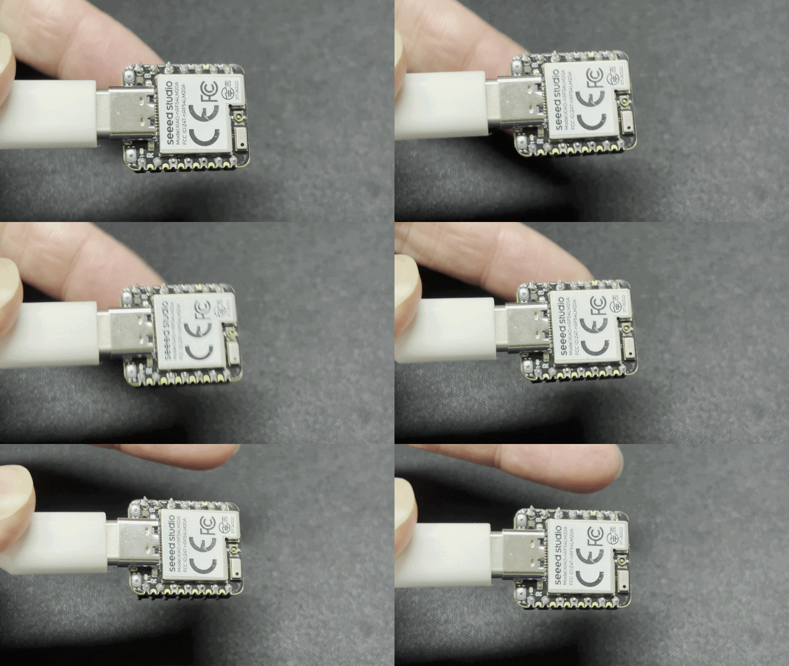
- Ao mesmo tempo, as informações do evento de toque também serão exibidas pela porta serial.
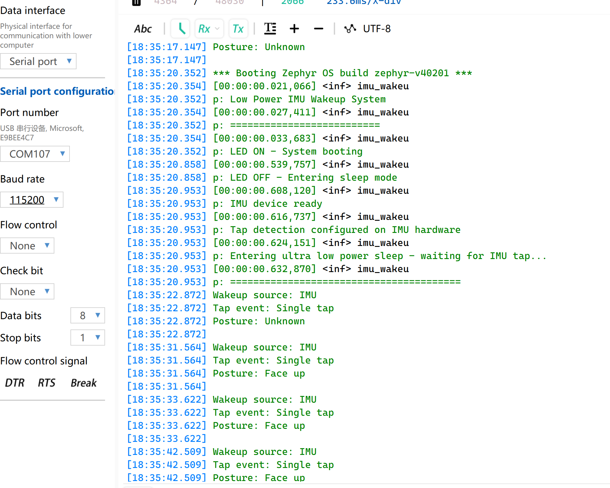
A posição de detecção é apenas para referência. O reconhecimento preciso da posição do toque depende do algoritmo de controle de fusão do IMU.
RTC
O chip adotado pelo XIAO nRF54LM20A Sense é equipado com recursos de hardware GRTC integrados, permitindo funções de RTC sem módulos RTC adicionais.
O RTC oferece suporte à contagem de carimbos de data e hora e pode registrar o tempo de operação mesmo após uma falha de energia, o que facilita o registro de logs e o rastreamento de tempo.
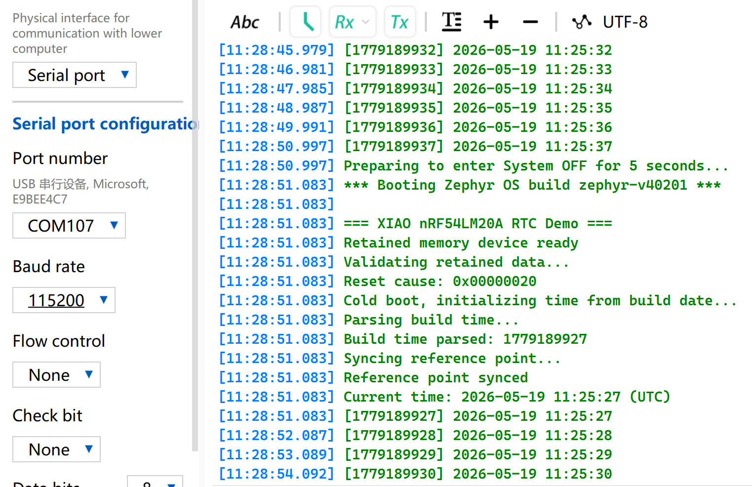
Esta seção apresenta um programa de exemplo implementado no XIAO nRF54LM20A Sense. Após a energização, ele obtém carimbos de data e hora a partir do horário de compilação por meio do RTC e imprime os dados a cada segundo. Após entrar no modo System OFF, o sistema será acordado pelo alarme do RTC para continuar a contagem.
-
Copie o arquivo rtc-main.c para o arquivo main.c. Use as funções do RTC para imprimir o carimbo de data e hora.
-
Modifique a árvore de dispositivo
app.overlaypara habilitar o nó do RTC.
/ {
    cpuapp_sram@2007ec00 {
        compatible = "zephyr,memory-region", "mmio-sram";
        reg = <0x2007ec00 DT_SIZE_K(4)>;
        zephyr,memory-region = "RetainedMem";
        status = "okay";

        retainedmem0: retainedmem {
            compatible = "zephyr,retained-ram";
            status = "okay";
        };
    };

    aliases {
        retainedmemdevice = &retainedmem0;
    };
};

&cpuapp_sram {
    /* Shrink SRAM to avoid overlap with retained memory region:
     * 511 - 4 = 507 KB = 0x7EC00
     */
    reg = <0x20000000 DT_SIZE_K(507)>;
    ranges = <0x0 0x20000000 0x7ec00>;
};
- Edite o arquivo prj.conf para habilitar as configurações relevantes do RTC.
# Console and serial
CONFIG_SERIAL=y
CONFIG_CONSOLE=y
CONFIG_PRINTK=y

# Power management and System OFF
CONFIG_PM=y
CONFIG_PM_DEVICE=y
CONFIG_POWEROFF=y

# Hardware info (reset cause detection)
CONFIG_HWINFO=y

# Retained memory (survives System OFF)
CONFIG_RETAINED_MEM=y

# CRC for retained data validation
CONFIG_CRC=y

# Newlib C library (required for sscanf, strcmp etc.)
# Note: mktime() and gmtime() are NOT used — custom tm_to_unix()
# and unix_to_tm() avoid newlib's TZ environment dependency.
CONFIG_NEWLIB_LIBC=y
Resultado
- O programa começa a contar a partir do momento de compilação e gravação. Abra a ferramenta de porta serial para observar o efeito de execução, e todas as funções esperadas são implementadas.
MIC
O XIAO nRF54LM20A Sense está equipado com o microfone digital MEMS MSM261DGT006 para entrada de voz. Ele se conecta diretamente via interface PDM sem necessidade de um ADC. É adequado para dispositivos vestíveis, dispositivos inteligentes, reconhecimento de voz, gravação de áudio e outros cenários de aplicação que exigem funções de detecção acústica.
Entre a série XIAO nRF54LM20A, apenas o XIAO nRF54M20A Sense está equipado com um microfone, que está localizado no canto inferior esquerdo da placa de desenvolvimento.
Gravação de áudio e upload via BLE
Esta seção demonstra a função do microfone por meio de um exemplo de voz. O processo específico é o seguinte:
- Pressione o botão BOOT, o LED RGB-G permanecerá aceso e iniciará a gravação; pressione-o novamente para parar a gravação (máximo de 10 segundos).
- Após a gravação, o arquivo de áudio será enviado ao computador host via Bluetooth. O LED RGB-G pisca durante a transmissão.
- Execute o script de recepção no Windows para salvar o arquivo de áudio no diretório
./recordings. - O LED RGB-G apaga após a conclusão da transmissão.
-
Copie o programa de mic-main.c para
main.c. -
Modifique o arquivo de árvore de dispositivo
app.overlaypara vincular o nó BLE.
/*
 * XIAO nRF54LM20A BLE recorder devicetree overlay
 *
 * Logging uses the board's UART20 debug bridge at 115200 baud.
 */

/* Keep the board debug UART configuration explicit and reproducible. */
&uart20 {
	current-speed = <115200>;
	status = "okay";
};

/* Enable the PDM microphone interface. */
&pdm20 {
	status = "okay";
};

/* Enable the external 8 MB SPI NOR flash used for PCM storage. */
&py25q64 {
	status = "okay";
};

/ {
	chosen {
		zephyr,bt-hci = &bt_hci_controller;
	};
};

/* dmic_vdd is the board-defined nPM1300 LDO1 3.3 V supply. The application
 * enables it at runtime. power_en is defined by the board devicetree.
 */
&dmic_vdd {
	/delete-property/ regulator-boot-on;
};
- Modifique o arquivo
prj.confpara habilitar as configurações de Bluetooth e microfone, e defina o nome do dispositivo Bluetooth como XIAO-MIC.
# ===== Audio / DMIC =====
CONFIG_AUDIO=y
CONFIG_AUDIO_DMIC=y

# ===== GPIO =====
CONFIG_GPIO=y

# I2C and PMIC support for the nPM1300 microphone supply
CONFIG_I2C=y
CONFIG_MFD=y
CONFIG_REGULATOR=y

# Logging over the board UART debug bridge
CONFIG_LOG=y
CONFIG_LOG_BACKEND_UART=y

# Serial and console
CONFIG_SERIAL=y
CONFIG_CONSOLE=y
CONFIG_UART_CONSOLE=y

# Disable the Arm MPU for compatibility with early LM20A silicon.
CONFIG_ARM_MPU=n

# ===== BLE =====
CONFIG_BT=y
CONFIG_BT_PERIPHERAL=y
CONFIG_BT_DEVICE_NAME="XIAO-MIC"
CONFIG_BT_DEVICE_APPEARANCE=833
CONFIG_BT_MAX_CONN=1
CONFIG_BT_MAX_PAIRED=1
CONFIG_BT_LOG_LEVEL_ERR=y
CONFIG_BT_AUTO_PHY_UPDATE=n
CONFIG_BT_GAP_AUTO_UPDATE_CONN_PARAMS=n
CONFIG_BT_CTLR_CONN_PARAM_REQ=n
CONFIG_BT_DATA_LEN_UPDATE=n
CONFIG_BT_BUF_ACL_TX_SIZE=251
CONFIG_BT_BUF_ACL_TX_COUNT=32
CONFIG_BT_BUF_EVT_RX_COUNT=33
CONFIG_BT_BUF_ACL_RX_SIZE=251
CONFIG_BT_L2CAP_TX_MTU=247
CONFIG_BT_L2CAP_TX_BUF_COUNT=24
CONFIG_BT_L2CAP_TX_FRAG_COUNT=12
CONFIG_BT_ATT_TX_COUNT=24
CONFIG_BT_CONN_TX_MAX=32
CONFIG_BT_ZEPHYR_NUS=y
CONFIG_BT_ZEPHYR_NUS_DEFAULT_INSTANCE=y

# Memory
CONFIG_HEAP_MEM_POOL_SIZE=16384
CONFIG_SYSTEM_WORKQUEUE_STACK_SIZE=4096

# External SPI NOR flash (8 MB PY25Q64HA)
CONFIG_SPI=y
CONFIG_SPI_NOR=y
CONFIG_FLASH=y
CONFIG_FLASH_PAGE_LAYOUT=y

# Assertions
CONFIG_ASSERT=y
CONFIG_BT_CTLR_ASSERT_OPTIMIZE_FOR_SIZE=n
Resultado
Compile e grave o programa e, em seguida, use um computador com Windows para receber o áudio gravado via Bluetooth com a ajuda de scripts.
- Execute o script em Python
Instale as bibliotecas dependentes necessárias antes da execução:
pip install bleak
Copie o arquivo de script em Python.
ble_recorder_receiver.py
#!/usr/bin/env python3
"""
BLE recorder receiver for the XIAO nRF54LM20A.

Continuously scans for "XIAO-MIC", connects, subscribes to NUS notifications,
saves WAV data, and reconnects automatically. Each RIFF header starts a new file.

Usage:       python ble_recorder_receiver.py
Dependency:  pip install bleak

Firmware operation:
  Press BOOT once to begin recording (green LED on).
  Press BOOT again, or wait 10 seconds, to begin transfer (green LED blinking).
  The green LED turns off when the transfer is complete.
"""

import asyncio
import os
import sys
from datetime import datetime

from bleak import BleakClient, BleakError, BleakScanner

NUS_SERVICE_UUID = "6e400001-b5a3-f393-e0a9-e50e24dcca9e"
NUS_TX_CHAR_UUID = "6e400003-b5a3-f393-e0a9-e50e24dcca9e"  # Device-to-host notifications

DEVICE_NAME = "XIAO-MIC"
OUTPUT_DIR = "./recordings"
SCAN_TIMEOUT = 10.0
RECONNECT_DELAY = 2.0
RIFF_MAGIC = b"RIFF"
WAV_HEADER_SIZE = 44
WAV_DATA_SIZE_OFFSET = 40


class RecordingWriter:
    """Write NUS notification data to WAV files, splitting on RIFF headers."""

    def __init__(self):
        self.path = None
        self.file = None
        self.total = 0
        self.expected_total = None
        self.header = bytearray()

    def _open(self):
        os.makedirs(OUTPUT_DIR, exist_ok=True)
        stamp = datetime.now().strftime("%Y%m%d_%H%M%S_%f")
        self.path = os.path.join(OUTPUT_DIR, f"recording_{stamp}.wav")
        self.file = open(self.path, "wb")
        self.total = 0
        self.expected_total = None
        self.header.clear()
        print(f"\nNew recording -> {self.path}")

    def on_notification(self, _sender, data):
        # Finalize the current file before starting a new RIFF stream.
        if data[:4] == RIFF_MAGIC and self.total > 0:
            self.close()
        if self.file is None:
            self._open()
        self.file.write(data)
        self.total += len(data)

        if len(self.header) < WAV_HEADER_SIZE:
            needed = WAV_HEADER_SIZE - len(self.header)
            self.header.extend(data[:needed])
            if len(self.header) == WAV_HEADER_SIZE and self.header[:4] == RIFF_MAGIC:
                data_size = int.from_bytes(
                    self.header[WAV_DATA_SIZE_OFFSET:WAV_HEADER_SIZE],
                    byteorder="little",
                )
                self.expected_total = WAV_HEADER_SIZE + data_size

        sys.stdout.write(f"\rReceiving: {self.total} bytes")
        sys.stdout.flush()

        if self.expected_total is not None and self.total >= self.expected_total:
            self.close()

    def close(self):
        if self.file:
            self.file.flush()
            self.file.close()
            self.file = None
            if self.total > 44:
                tag = "WAV, playable"
            elif self.total > 0:
                tag = "incomplete (header only)"
            else:
                tag = "empty"
            print(f"\nSaved: {self.path} ({self.total} bytes) [{tag}]")
            self.total = 0
            self.expected_total = None
            self.header.clear()


async def connect_and_receive(writer):
    while True:
        print(f"\nScanning for '{DEVICE_NAME}'...")
        device = await BleakScanner.find_device_by_name(DEVICE_NAME,
                                                         timeout=SCAN_TIMEOUT)
        if device is None:
            print(f"Not found, retrying in {RECONNECT_DELAY:.0f}s"
                  " (check: board powered on, Bluetooth enabled)")
            await asyncio.sleep(RECONNECT_DELAY)
            continue

        print(f"Found: {device.name} ({device.address}), connecting...")
        disconnect_event = asyncio.Event()

        def on_disconnect(_c):
            disconnect_event.set()

        try:
            async with BleakClient(
                device.address,
                disconnected_callback=on_disconnect,
                timeout=30.0,
                services=[NUS_SERVICE_UUID],
            ) as client:
                print("Connected")
                await client.start_notify(NUS_TX_CHAR_UUID,
                                          writer.on_notification)
                print("Subscribed to NUS, waiting for audio data...")
                print("(Press BOOT on the board to record; press again or wait 10s to transfer)")
                await disconnect_event.wait()
        except BleakError as e:
            print(f"\nBLE error: {e}")
        except asyncio.TimeoutError:
            print("\nConnection timed out")

        writer.close()
        print(f"Disconnected, reconnecting in {RECONNECT_DELAY:.0f}s...")


async def main():
    print(f"=== BLE receiver '{DEVICE_NAME}', Ctrl+C to quit ===\n")
    writer = RecordingWriter()
    try:
        await connect_and_receive(writer)
    except KeyboardInterrupt:
        pass
    finally:
        writer.close()
        print("Stopped.")


if __name__ == "__main__":
    try:
        asyncio.run(main())
    except KeyboardInterrupt:
        print("\nStopped.")
Comando de execução do script:
python ble_recorder_receiver.py
O UUID BLE já está configurado no programa Python, portanto a conexão será feita automaticamente após executar o script.
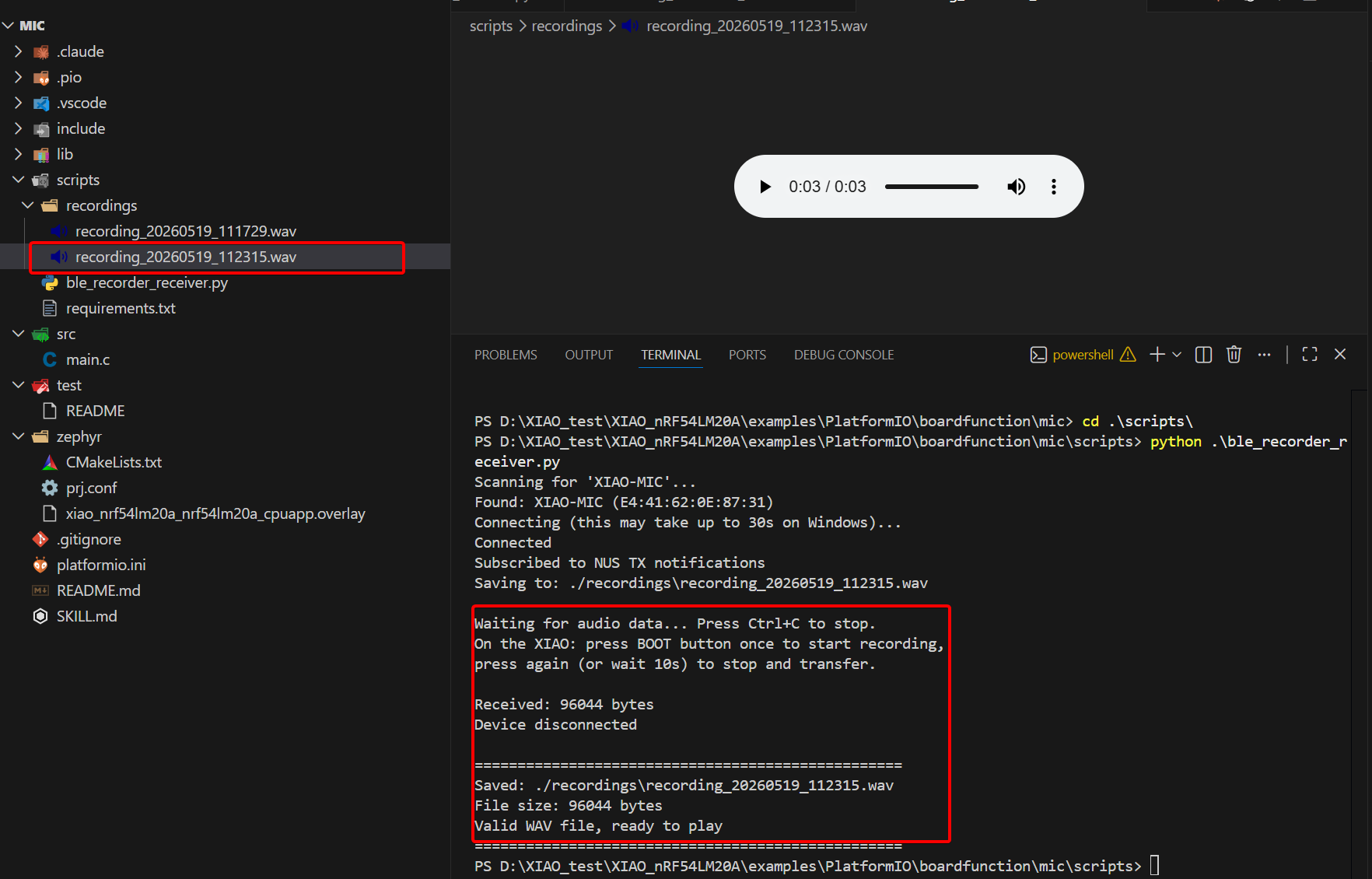
- Verificar o resultado
- Pressione a tecla BOOT para iniciar a gravação. O LED RGB verde constante indica que a gravação está em andamento. Você pode falar em voz alta em direção ao microfone e, em seguida, pressionar a tecla BOOT novamente para parar a gravação. O LED RGB verde piscando significa que o arquivo de áudio está sendo transmitido.
- Abra a porta serial; o log será impresso. Defina a taxa de baud para 921600.
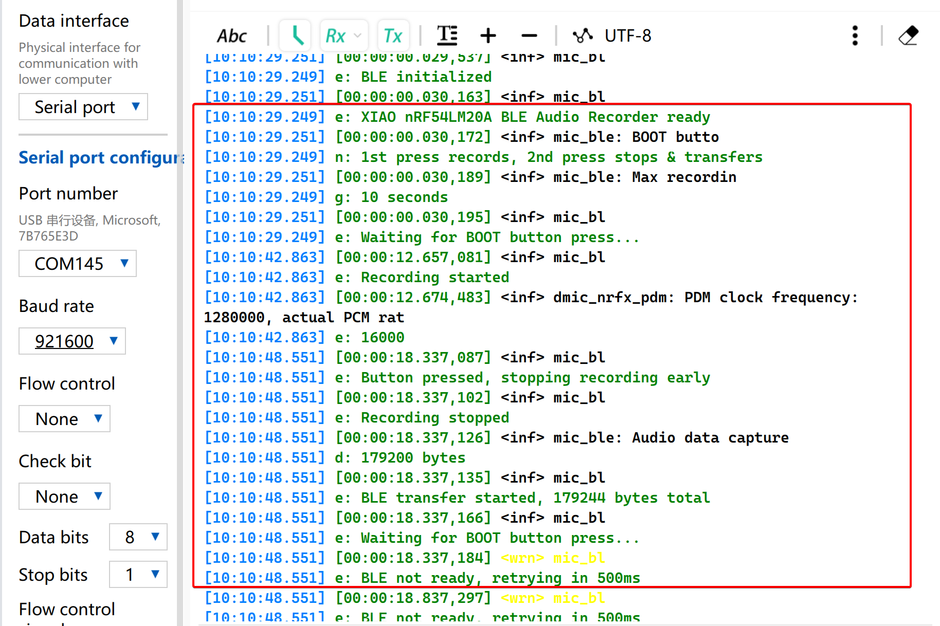
- O arquivo de áudio recebido e seu tamanho em bytes serão exibidos.
Suporte Técnico e Discussão de Produtos
Obrigado por escolher nossos produtos! Estamos aqui para oferecer diferentes tipos de suporte para garantir que sua experiência com nossos produtos seja a mais tranquila possível. Oferecemos vários canais de comunicação para atender a diferentes preferências e necessidades.