Hardware Layout for reComputer

You will get the basic idea of the reComputer for Jetson Series hardware layout here. Meanwhile, you will know how to remove and install the core board from the carrier board, how to install the camera, M.2 Wi-Fi module or hard disk, etc.
reComputer Series Placement
When facing the backplane of the reComputer interface, there are 4 anti-skid pads on the right side of the chassis for easy standing, as shown in the figure below.

The bottom of the reComputer chassis is a suspended structure, and the chassis can be fixed on some inconvenient structures with binding tapes. The chassis bottom plate has 4 fixing holes to facilitate fixing on the facade or slope.

reComputer Series Top Cover
When facing the backplane of the reComputer interface, there are 4 anti-skid pads on the right side of the chassis, where a metal button can be seen, as shown in the following figure:

Push the button up to lift the top cover of the case, and then you can lift it open to remove the top cover.

Remove the Core Board from the Carrier Board
After opening the chassis, you can see the module inserted on the carrier board, as shown in the following figure. The module can be removed from the carrier board by following the steps below.

-
Step 1: Before removing the core version, first you must confirm whether the fan power supply is connected. If it is, you need to unplug the fan power supply from the plug (For Jetson Nano there may not be a fan and you can skip this step).
-
Step 2. Remove the screws that hold the core plate with a cross screwdriver.

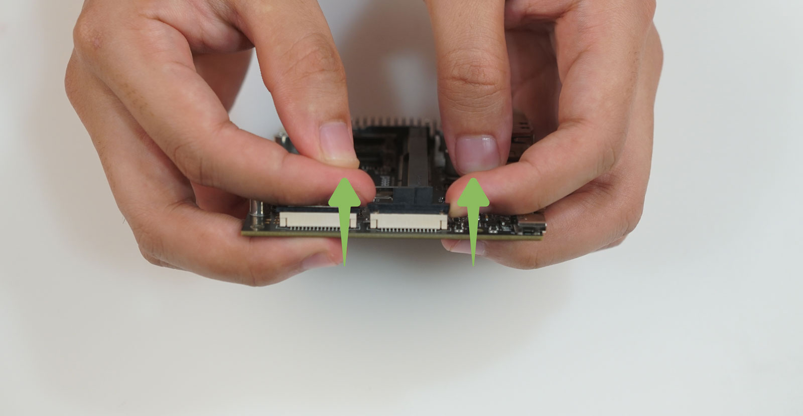
- Step 3. Open the clamp on the carrier plate outward, and the core plate will spring up automatically.

- Step 4. Remove the core board diagonally upwards.

Mount the Module on the Carrier Coard
- Step 1. Find the corresponding Jetson SODIMM connector fingers on the carrier board and the connector on the module.

- Step 2. Insert the module diagonally about 20 degrees into the slot of the carrier plate. Press down and it will be fixed on the carrier board.

!!! Note You may find that under the correct installation there are a few connector fingers shown at the interface. It will be unstable once many connector fingers are exposed.

- Step 3. Use a cross screwdriver to tighten the screws.
- Step 4. If the module includes a cooling fan, plug the fan's power plug into the power socket on the carrier board.
Remove Carrier Coard from the reComputer Chassis
When we want to install the M.2 module or CSI camera and other operations, we will need to remove the carrier board from the reComputer chassis for more easier operation. The carrier board is fixed to the chassis base with 4 screws, as shown in the following figure:

Remove the 4 fixing screws as shown below:

Take the carrier board together with the module out of the chassis:

Equip the reComputer with a Camera Module
Both reComputer carrier boards have two CSI interfaces. The interfaces are usually used to connect a camera for some identification projects. Here we take the J1010 carrier board as an example to guide you to equip and use the Raspberry Pi Camera Module V2 on the reComputer.
- Step 1. Mount the camera module on the carrier board
!!!Note Before installation, please turn off the reComputer, unplug the power supply, and open the top cover of the chassis. For the convenience of demonstration below, we removed the carrier board from the chassis and the module. The actual operation only needs to open the top cover.
Select the CSI connector you want to use, then gently flip up the black retention slots on both sides.
Make sure to set the black slot aside before inserting the cable into the slot.
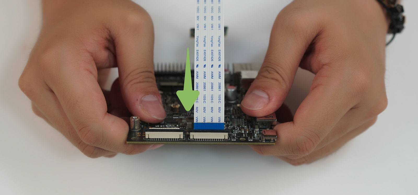
Watch out the direction of the cable. You can see that the side of the cable pin is facing the carrier board, and the blue side is facing out.

- Step 2. Power on and start reComputer.
After plugging in the camera cable, make sure that the module, carrier board and peripherals are all installed in place. And then power on.
- Step 3. Check if the camera is recognized.
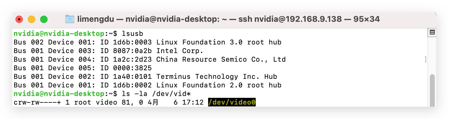
Enter the following command in the command line window to see if a camera device is currently available.
ls /dev/video0
If the output shows as below, it means that the camera has been successfully detected.
If you don't see the device file, check whether your ribbon is oriented correctly and make sure your Raspberry Pi camera is V2 version as the V1 version is not recognized.
- Step 4. Apply the Camera
You can use the sensor_mode attribute with the GStreamer nvarguscamerasrc element to specify which camera. Valid values are 0 or 1 (defaults to 0 if not specified), i.e.
# Simple Test
# Ctrl^C to exit
# sensor_id selects the camera: 0 or 1 on Jetson Nano B01
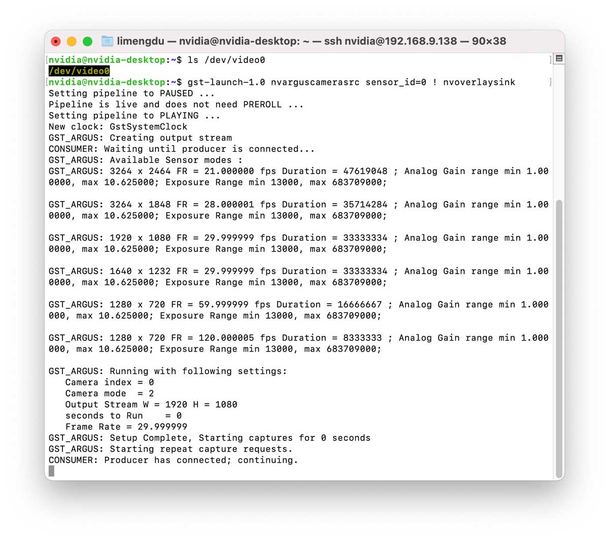
$ gst-launch-1.0 nvarguscamerasrc sensor_id=0 ! nvoverlaysink
You can use the following commands in the command line window to test the usage of the camera.
After running this command, reComputer will display the screen captured by the camera in full screen until you press Ctrl+C.
If you have more camera usage needs, you can refer to the CSI-Camera project to explore and learn by yourself.
Equip the Wireless Module for the reComputer
Here we will show you how to install an M.2 Key E wireless module on the reComputer.
Equipment and accessories required:
- reComputer
- Intel® Dual Band Wireless-AC 8265 wireless module
- 2 x IPEX to SMA Female External Antenna Adapter and SMA Male Antenna for WIFI Module
- Phillips screwdriver and screws

!!!Note Installing the wireless module of the M.2 Key E requires additional antennas. Because the module is in the chassis, it may even be pressed between the module and the carrier board. Without antennas, the signal strength will be greatly affected.
- Step 1. Detach the carrier board from the reComputer chassis
Before installing the wireless module, detach the carrier board from the reComputer chassis as shown below:

- Step 2. Remove the case silicone plug
There are 4 reserved antenna openings in the chassis, where are plugged with silicone plugs, as shown in the figure below.

Select the two outer holes, squeeze the silicone plug from the outside of the chassis to the inside of the chassis, and then pull out the silicone plug from the inside to expose the antenna hole.

- Step 3. Install the SAM header
As shown in the figure below, install the nut and nut of the SAM head to the wifi hole, paying attention to place the cable end in the chassis.

- Step 4. Insert the wireless module into the M.2 Key E port
!!!Note The M.2 Key E interface is on the bottom or top of the carrier board. For different carriers, please refer to Carrier Board Hardware Layout. Before installation, you may want to remove the core board from the carrier board.
As shown in the figure below, find the M.2 Key E interface on the carrier board, and insert the wireless module into the interface slot.

After the wireless module is firmly inserted, fix it with screws.

- Step 5. Insert 2 IPEX plugs into the corresponding sockets of the wireless module, the connection is a button connection, as shown in the figure below. Simply press it and no more operations are required.

The installation should be like the figure shown below. At this time, be careful not to break the wire between the wireless module and the SAM antenna base.

- Step 6. Install the module to the chassis
Place carefully the carrier board into the reComputer chassis and then install the screws.

- Step 7. Equip antennas
Install two SAM male antennas to the SAM female sockets and tighten. That will be all the hardware installation.

- Step 8. Power on the reComputer and connect to the wireless network
Connect the peripherals to the reComputer and then power on. Enter the system and open the network option in the upper right corner of the screen. After checking the Enable Wi-Fi option, you will see the nearby wireless network. Select the available wireless network connection.

Congratulations, you have successfully installed the wireless module and connected to the network.
Hardware Layout
J101 carrier board
Top View

J202 carrier board
Top View

Bottom View

Jetson A206 carrier board(equipped with Jetson Nano)
Click here to check out the pins of Jetson A206 carrier board(equipped with Jetson Nano) to the operating interfaces.
Top View

Bottom View

Jetson A206 carrier board (equipped with Jetson Xavier NX)
Click here to check out the pins of Jetson A206 carrier board(equipped with Jetson Nano) to the operating interfaces.
Top View

Bottom View

Detailed Comparison
| Product | reComputer J1010 | reComputer J1020 | reComputer J2011 | reComputer J2012 |
|---|---|---|---|---|
| Module | Nano | Nano | Xavier NX | Xavier NX 16GB |
| AI Perf | 472 GFLOPS | 472 GFLOPS | 21 TOPS | 21 TOPS |
| GPU | 128-core NVIDIA Maxwell™ | 128-core NVIDIA Maxwell™ | 384-core NVIDIA Volta™ GPU | 384-core NVIDIA Volta™ GPU |
| CPU | Quad-core ARM A57 @ 1.43 GHz | Quad-core ARM A57 @ 1.43 GHz | 6-core NVIDIA Carmel ARM®v8.2 64-bit CPU 6 MB L2 + 4 MB L3 | 6-core NVIDIA Carmel ARM®v8.2 64-bit CPU 6 MB L2 + 4 MB L3 |
| Memory | 4GB 64-bit LPDDR4 25.6GB/s | 4GB 64-bit LPDDR4 25.6GB/s | 8 GB 128-bit LPDDR4x 59.7GB/s | 8 GB 128-bit LPDDR4x 59.7GB/s |
| Storage | 16 GB eMMC | 16 GB eMMC | 16 GB eMMC | 16 GB eMMC |
| VIDEO ENCODER | 4K30 | 2x1080p60 | 4x1080p30 | 4x720p60 | 9x720p30 (H.265 & H.264) | 4K30 | 2x1080p60 | 4x1080p30 | 4x720p60 | 9x720p30 (H.265 & H.264) | 2x 4K60 | 4x 4K30 | 10x 1080p60 | 22x 1080p30 (H.265) 2x 4K60 | 4x 4K30 | 10x 1080p60 | 20x 108p30 (H.264) | 2x 4K60 | 4x 4K30 | 10x 1080p60 | 22x 1080p30 (H.265) 2x 4K60 | 4x 4K30 | 10x 1080p60 | 20x 108p30 (H.264) |
| VIDEO DECODER | 4K60 | 2x 4K30 | 4x 1080p60 | 8x 1080p30 | 9x 720p60 (H.265 & H.264) | 4K60 | 2x 4K30 | 4x 1080p60 | 8x 1080p30 | 9x 720p60 (H.265 & H.264) | 2x 8K30 | 6x 4K60 | 12x 4K30 | 22x 1080p60 | 44x 1080p30 (H.265) 2x 4K60 | 6x 4K30 | 10x 1080p60 | 22x 1080p30 (H.264) | 2x 8K30 | 6x 4K60 | 12x 4K30 | 22x 1080p60 | 44x 1080p30 (H.265) 2x 4K60 | 6x 4K30 | 10x 1080p60 | 22x 1080p30 (H.264) |
| Gigabit Ethernet | 1x RJ45 Gigabit Ethernet Connector (10/100/1000) | 1x RJ45 Gigabit Ethernet Connector (10/100/1000) | 1x RJ45 Gigabit Ethernet Connector (10/100/1000) | 1x RJ45 Gigabit Ethernet Connector (10/100/1000) |
| USB | 1 x USB 3.0 Type A Connector; 2 x USB 2.0 Type A Connector; 1 x USB Type C for Device mode; 1 x USB Type C for 5V power input | 4 x USB 3.0 Type A Connector; 1 x Micro-USB port for Device mode; | 4 x USB 3.0 Type A Connector; 1 x Micro-USB port for Device mode; | 4 x USB 3.0 Type A Connector; 1 x Micro-USB port for Device mode; |
| CSI Camera Connect | 2x CSI Camera (15 pos, 1mm pitch, MIPI CSI-2 ) | 2x CSI Camera (15 pos, 1mm pitch, MIPI CSI-2 ) | 2x CSI Camera (15 pos, 1mm pitch, MIPI CSI-2 ) | 2x CSI Camera (15 pos, 1mm pitch, MIPI CSI-2 ) |
| Display | 1x HDMI Type A | 1xHDMI Type A; 1xDP | 1xHDMI Type A; 1xDP | 1xHDMI Type A; 1xDP |
| FAN | 1x FAN(5V PWM) | 1x FAN(5V PWM) | 1x FAN(5V PWM) | 1x FAN(5V PWM) |
| M.2 KEY E | 1x M.2 Key E | 1x M.2 Key E(Disabled) | 1x M.2 Key E | 1x M.2 Key E |
| M.2 KEY M | - | 1x M.2 Key M | 1x M.2 Key M | 1x M.2 Key M |
| RTC | 1x RTC Socket | 1x RTC socket | 1x RTC Socket | 1x RTC Socket |
| Multifunctional port | 1x 40-Pin header | 1x 40-Pin header | 1x 40-Pin header | 1x 40-Pin header |
| Power | USB-Type C 5V⎓3A; | DC Jack 12V/2A | DC Jack 19V/4.74A (MAX 90W) MAX | DC Jack 19V/4.74A (MAX 90W) MAX |
| Mechanical | 130 mm x 120 mm x 50 mm | 130mm x120mm x 50mm | 130mm x120mm x 50mm | 130mm x120mm x 50mm |
Carrier Board Technical Specification
| Connector | J1010 Carrier Board | Jetson A206 Carrier Board |
|---|---|---|
| Jetson module connector | 1x Jetson SODIMM connector, 260-pin | 1x Jetson SODIMM connector, 260-pin |
| USB Type A | 1x USB 3.0 Type-A Connector 2x USB 2.0 Type A connectors | 4x USB 3.0 Type-A Connectors |
| USB Micro Type B | - | 1x USB Micro B, RA Female |
| USB Type C | 2x Type C connector | - |
| Ethernet Port | 1x RJ45 Gigabit Ethernet Connector (10/100/1000) | 1x RJ45 Gigabit Ethernet Connector (10/100/1000) |
| Display Port | 1xHDMI type A | 1xHDMI type A and 1xDP |
| CSI Camera Connector | 2x CSI Camera (15 pos, 1mm pitch, MIPI CSI-2 ) | 2x CSI Camera (15 pos, 1mm pitch, MIPI CSI-2 ) |
| M.2 Key E | 1x M.2 Key E Slot (75-pin) 2230 | 1x M.2 Key E Slot (75-pin) 2230 |
| M.2 Key M | - | 1x M.2 Key M Slot (75-pin) NVME 2280 |
| Multifunctional Port | 2.0 Pitch 40 PIN | 2.0 Pitch 40 PIN |
| Button Header | 1x Button Header (1x12, 2.54mm pitch, RA) | 1x Button Header (1x12, 2.54mm pitch, RA) |
| FAN Connector | 1x Picoblade Header | 1x Picoblade Header |
| CAN | Diasabled | 1x CAN Bus Header (1x4, 2.54mm pitch, RA) |
| RTC | 1x RTC Back-up Coin Cell Socket (CR1220) | 1x RTC Back-up Coin Cell Socket (CR1225) |
| Power | 1x Type C connector | 1x DC Input Power TE Connector |
Tech Support & Product Discussion
Thank you for choosing our products! We are here to provide you with different support to ensure that your experience with our products is as smooth as possible. We offer several communication channels to cater to different preferences and needs.