reComputer R1000 with FIN to create a Equip Graphic
Introduction
FIN Framework (FIN) is a software framework with application suites that can integrate, control, manage, analyze, visualize and connect. Its capabilities can be integrated by OEMs into a range of products and services.
This article will show you how to use the Graphics Builder of FIN Framwork, and to create a Equip Graphic using the Graphics Builder.
Getting Start
Before you start this project, you may need to prepare your hardware and software in advance as described here.
Hardware Preparation
| reComputer R1000 |
|---|
 |
Software Preparation
- Regarding how to install FIN Framwork, you can refer to this wiki.
Steps of create a Equip Graphic
Create new Equip Graphic
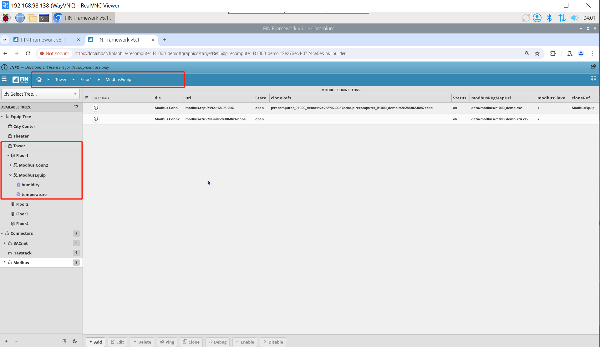
Step 1: Please put the context under the path Tower => Floor1 => ModbusEquip.
Step 2: Create a new Equip Graphic. Click Graphic Builder => new, and according to the system context, a pop-up window named Create a Graphic will appear:
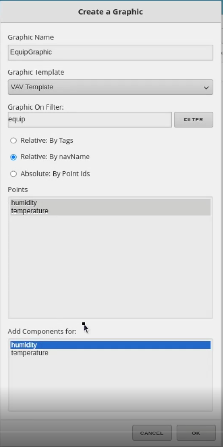
The pop-up window mainly has the following attributes:
- Graphic Name: Allows you to type in a name for the graphic.
- Graphic Template: Allows you to select a starter template from a list of available pre-built "duct templates." This is not a required parameter, just gives you a starting point of ductwork. (You can also create your own templates to be used here).
- Graphic On Filter: The Graphic On filter refers to the graphic's "graphicOn" tags, which determine what database records this graphic will run on. By default, this filter will automatically be filled in based on your context equipment. (In our example, I created the graphic while on a VAV, which is why this filter in the screenshot is filled in with that VAV's tags). This filter can be changed after the fact if the need arises.
- Relative - By Tags: This option makes it so that the points automatically come in Relative, based on their current tags. When points are relative, they are not "hardcoded" to one set of equipment's data. They are relative and will load on any equipment that has similar points based on the points' tags.
- **Relative - By navName:**This option makes it so that the points automatically come in Relative, based on their current navName. When points are relative, they are not "hardcoded" to one set of equipment's data. They are relative and will load on any equipment that has similar points based on the points' navName.
- Absolute - by Point Ids: This option makes it so that the points automatically come in Absolute (or
hardcoded) to the current equipment you are on. When a point is brought in "Absolute by Point id" the path is automatically hardcoded to get data from that exact point no matter where the graphic is loaded. - Points: This allows you to select which points you would like to bring into the graphic. By using the CTRL and/or SHIFT keys, you can select multiple points. The points are populated based on your context equipment. You also get points associated to that equip's refs. (In our example, the VAV has an ahuRef, so we are able to select points from the ahuRef to show in our graphic)
- Add Components For: This list is populated by the points you select in the previous "Points" section. By highlighting points in this section, you are telling FIN to automatically create a graphical component (based on its tags) and bind the point to the graphical component. This isn't required but can save time since it selects the component, brings it in, binds the point to it, and brings out a Display Label for it.
After the configuration is completed, click the OK button. A new graphic will appear on the right side. Click EquipGraphic => Edit to enter the editing interface.
Configure new Equip Graphic
Step 1:After entering the editing interface, the system will automatically generate smart labels and component based on the content selected in the Add Components for property. Move the control and click Magic Button => Smart Label to GraphicObjects to have the smart label automatically align with the control.
Step 2:Check Virtual point. You can click on the control through email and select Edit Properties. You can see virtual point in the new pop-up window, and you can modify it here; you can also view the virtual point corresponding to the control through ADVANCED in the lower left corner.
Step 3:Add new component and connect virtual point. In addition to the component automatically generated for us by the system, we can also add them ourselves. There are many component in the COMPONENTS box on the left. Drag the control with the left mouse button to the working control, then select the corresponding virtual point in the VIRTUAL POINTS column and drag it into the new home control. This way The binding of the new control to the virtual point is completed.
Step 4:Add Overview Box. We can add an Overview Box to display all values together. Click Overview Box => New and a new pop-up window will appear:
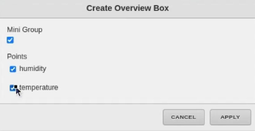
- Mini Group: If enabled, this will make the overview box appear with larger values and smaller title area. This box is smaller than the regular box and is recommended for scenarios where the box needs to be on the graphic, such as VFD (Spd,Cmd,Ena,Stat)
- Points: This will allow you to select which points to include in the overview box. TIP: If you had any smart labels selected before opening the Overview Box wizard, those points will already be selected in the list of points in the wizard.
After selecting the point, enter the window title in the next window, and finally click APPLY.
Step 5:Show results
Tech Support & Product Discussion
Thank you for choosing our products! We are here to provide you with different support to ensure that your experience with our products is as smooth as possible. We offer several communication channels to cater to different preferences and needs.