reComputer R1000 with FIN to create a Floor Graphic
Introduction
FIN Framework (FIN) is a software framework with application suites that can integrate, control, manage, analyze, visualize and connect. Its capabilities can be integrated by OEMs into a range of products and services.
This article will show you how to use the Graphics Builder of FIN Framwork, and to create a Floor Graphic using the Graphics Builder.
Getting Start
Before you start this project, you may need to prepare your hardware and software in advance as described here.
Hardware Preparation
| reComputer R1000 |
|---|
 |
Software Preparation
- Regarding how to install FIN Framwork, you can refer to this wiki.
- Regarding how to use the Modbus function of FIN framwork, you can refer to this wiki
Steps of create a Floor Graphic
Create new Floor Graphic
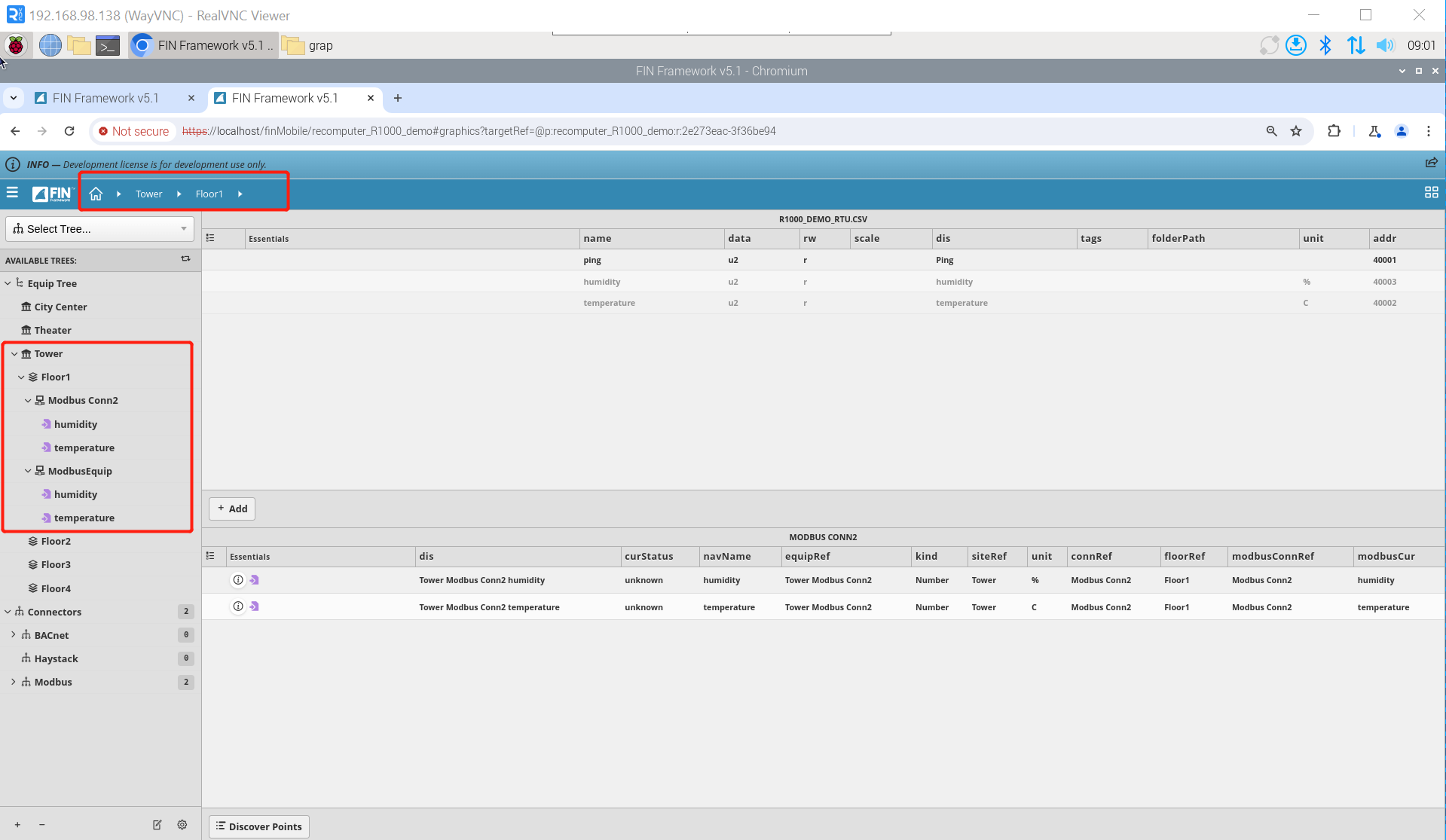
Step 1: We established a Modbus TCP connection and a Modbus RTU connection, and created the corresponding Equip. Each Equip has a label of humidty and temperature. For how to implement this step, you can refer to this wiki. At the same time, please put the context of FIN Framwork under the corresponding Floor. Here we put the context under Tower => Floor1.
Step 2: Create a new Floor Graphic and enter the editing interface. Click Graphic Builder => new, and the pop-up window of Create a Floorplan Graphic will appear.
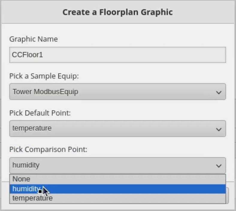
It has four attributes:
- Craphic Name
- Pick a Sample Equip
- Pick Default Point : Attributes that will be displayed in the graphic
- Pick Comparison Point : Reference point for color range
Clicking 'OK' will bring up a new pop-up window that lists' Equip 'with the same properties as' Pick Default Point'. Here, we select all of them and finally click 'OK'.
After that, our newly created Graphic will appear on the right side. Click CCFloor1 => Edit to enter the editing interface.
Configure new Site Graphic
Step 1: Import background image. First, select BACGROUND in the property bar in the lower left corner, select TYPE as IMAGE, then import the background image into the workspace, Select Center for the POSITION option and NO REPEAT for the REPEAT option. There are two ways to import background images. The first way is to drag it directly from the folder into the edit box; the second way is to click BROWSE in the lower left corner. If you have imported a certain image before, you can click here find that picture.
Step 2: Draw polygons. We use the polygon Tool to draw polygons to mark the position of each Equip.
Step 3: Add Virtual points. Switch to the Virtual points panel on the left, select the virtual point that matches the Equip we selected, and drag it into the drawn polygon.
Step 4: Add smart tags. Click on Magic Buttons => Smart Label to Polys to automatically place the label on the corresponding Virtual Points.
Step 5: Adjust the size of smart tags. You can click on the smart label to adjust its size. If you want to modify the size of multiple smart labels at the same time, you can click on Compulsions=>Smart label=>Select to select all smart labels, and then adjust their size
Step 6: Change the smart tag to non interactive so that the tag does not interfere with your operations

Step 7: Save and display the effect.
Tech Support & Product Discussion
Thank you for choosing our products! We are here to provide you with different support to ensure that your experience with our products is as smooth as possible. We offer several communication channels to cater to different preferences and needs.