reComputer R1000 with FIN Logic Builder
Introduction
FIN Framework (FIN) is a software framework with application suites that can integrate, control, manage, analyze, visualize and connect. Its capabilities can be integrated by OEMs into a range of products and services.
This article will show you how to use the Logic Builder of FIN Framwork, and to implement an alarm using the Logic Builder.We monitor the value of a Modbus device. When the value exceeds the critical value, FIN will alarm.
Getting Start
Before you start this project, you may need to prepare your hardware and software in advance as described here.
Hardware Preparation
| reComputer R1000 |
|---|
 |
Software Preparation
- Regarding how to install FIN Framwork, you can refer to this wiki.
- About reComputer R1000 using FIN for Modbus communication, you can refer to this wiki.
- Using modbusmechanic on W10 PC.You can also use other modbus testing tools.
Hardware Configuration
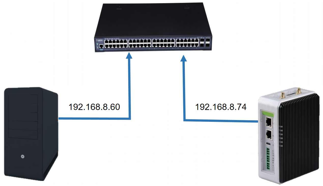
For ModbusTCP, we use Ethernet cables to connect the W10 PC and reComputer R1000 to a switch to ensure that they are on the same network segment.
Steps of implement an alarm
Create new Logic Builder program
Step 1: First click the directory bar at the top to switch the system directory to the desired target location.
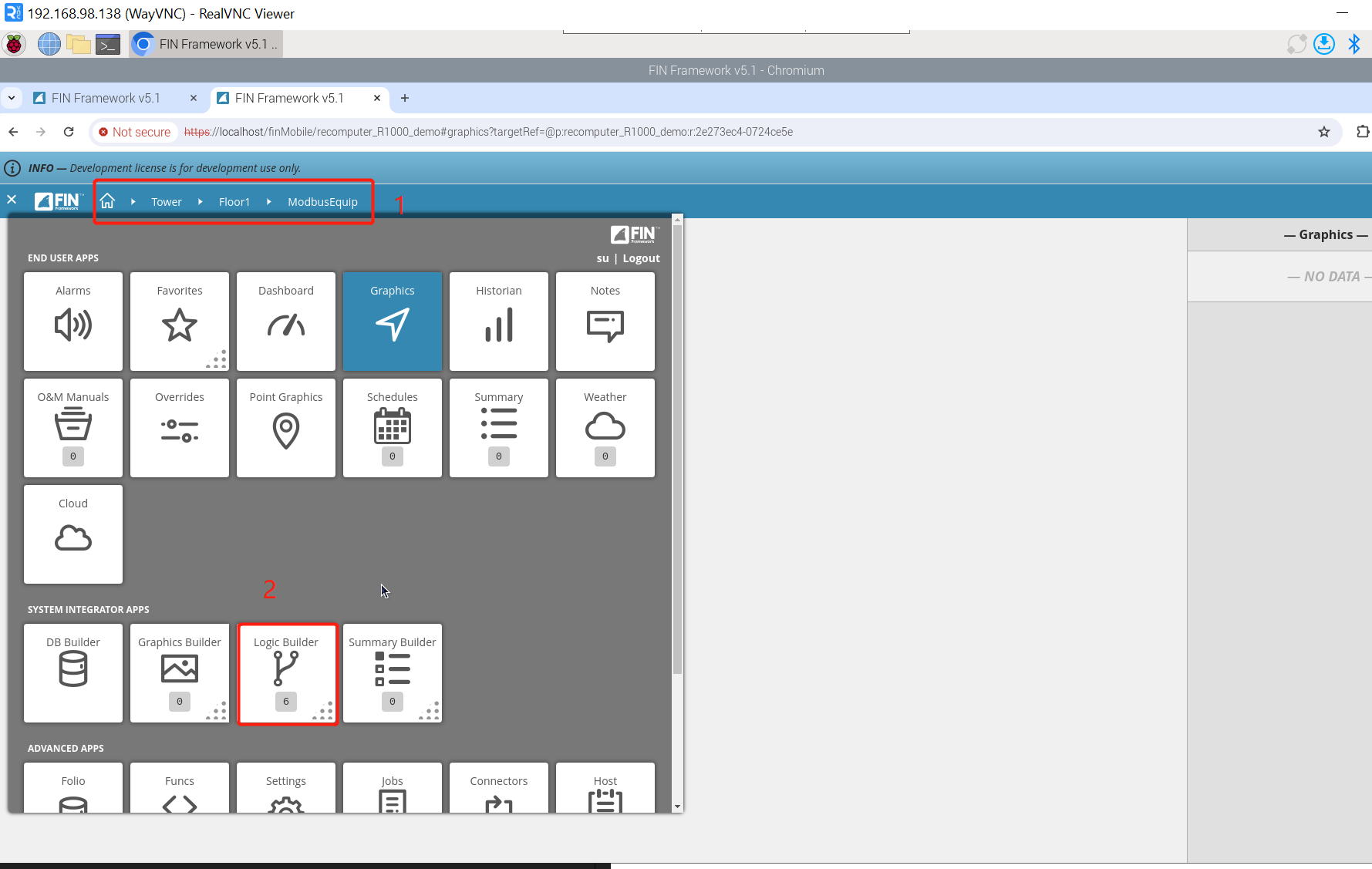
Step 2: Click Logic Builder => new on the setting interface, and the following pop-up window will appear:
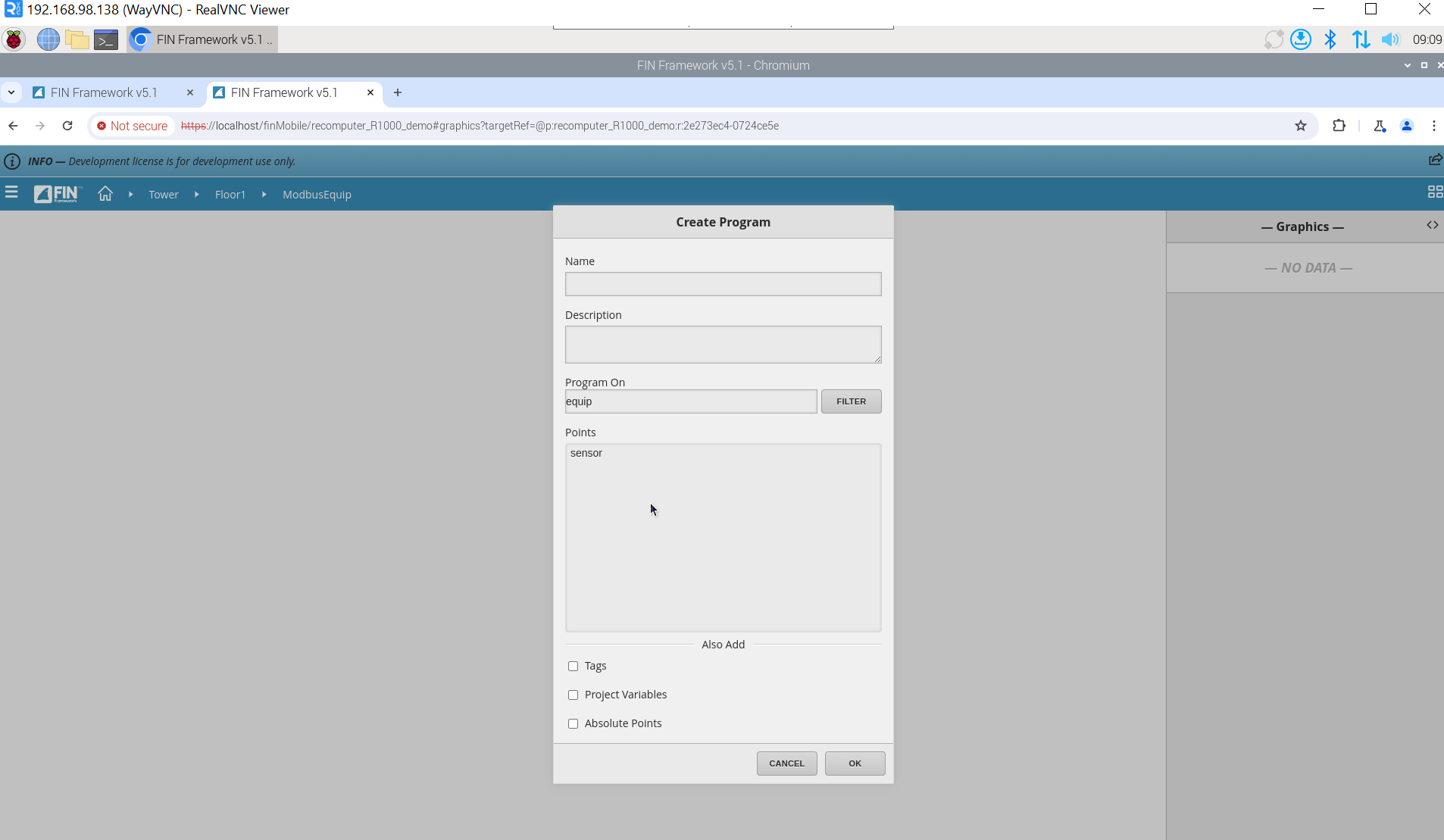
To fill in the following parameters:
- Name - Name of the program
- Description - Description for what the program is for/does
- Program On - Used to specify what the program will run on
- Points - Able to choose points from the equip to use
- Tags - Find tags used on equip or refs
- Project Variables - If other project variables exist on other programs, it provides a list of variables that can be used in the new program being create
- Absolute Points - Able to add hardcoded points based on their id
Points can enter multiple points, but we only entered one here. After filling in the information, click OK and click Edit in the pop-up window on the right to enter the Logic editing interface.
Configure Block logic
Step 1: Add an if block. There are two ways to add blocks in the workspace. The first is to click on the port of a block to add it, as shown in the figure:
The second way is to add through the search box in the lower left corner, as shown in the figure:
Step 2: Add the data points to be judged. On the left, you can see the data points we introduced when we created the Logic Builder program. It has two functions: get and set. Our logic is to determine whether the sensor value exceeds the critical value, so we choose get here. . Click get and drag it into the workspace, and a sensor block will appear.
Step 3: Add the >= block. We need to determine whether the sensor value exceeds the critical value, so we need to add a >= block, which will output a result to the if block. The if block determines the next step by judging the result of the >= block. action. Here we set the critical value to 23.
Step 4: Add a delay block. Sometimes we need to make the system more anti-interference, we can add a delay module, and the alarm will only occur after a certain condition is met for a certain period of time. We set the delay time to 3s and connect the output of the module to the if block.
Step 5: Create variables. When the sensor value exceeds the critical value, we can set a flag to mark the sensor value as abnormal. This flag can be implemented by creating a variable. variable has the following types:
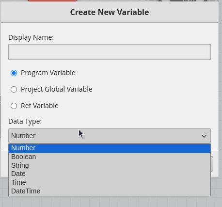
As shown in the figure, we added a variable named Alarm_bool, which also has set and get function blocks. We connect the set block of Alarm_bool after the if block. When the sensor value exceeds the critical value, it is set to True. When the sensor does not exceed the critical value, it is set to False.
Step 6: Click alarm at the top to enter the alarm configuration interface. Type alarm in the lower left corner to find alarmBlock and drag it into the workspace. We need to select the Alarm_bool variable we created for alarmBlock. When the Alarm_bool variable is True, the alarm will be triggered, and when the Alarm_bool variable is False, the alarm will not be triggered.
Alarm demonstration
Tech Support & Product Discussion
Thank you for choosing our products! We are here to provide you with different support to ensure that your experience with our products is as smooth as possible. We offer several communication channels to cater to different preferences and needs.