reComputer R1000 with FIN to use modbus TCP/RTU
Introduction
FIN Framework (FIN) is a software framework with application suites that can integrate, control, manage, analyze, visualize and connect. Its capabilities can be integrated by OEMs into a range of products and services.
This article introduces how to use the Modbus Connector of FIN Framwork, the use of Modbus TCP/RTU in FIN Framwork was explained in detail. which mainly includes three aspects: creating a FIN Framwork project, configure serial port number, configuring the Modbus Connector, and adding data points to Equip.
Getting Start
Before you start this project, you may need to prepare your hardware and software in advance as described here.
Hardware Preparation
| reComputer R1000 |
|---|
 |
Software Preparation
- Regarding how to install FIN Framwork, you can refer to this wiki.
- Regarding how to use the modbus function of reComputer R1000, you can refer to this wiki.
- Using modbusmechanic on W10 PC.You can also use other modbus testing tools.
Hardware Configuration
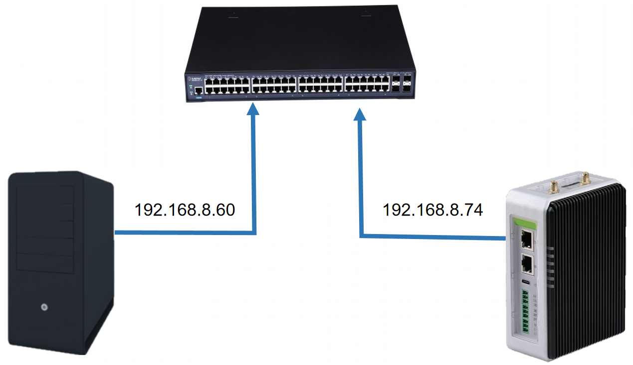
For ModbusTCP, we use Ethernet cables to connect the W10 PC and reComputer R1000 to a switch to ensure that they are on the same network segment.
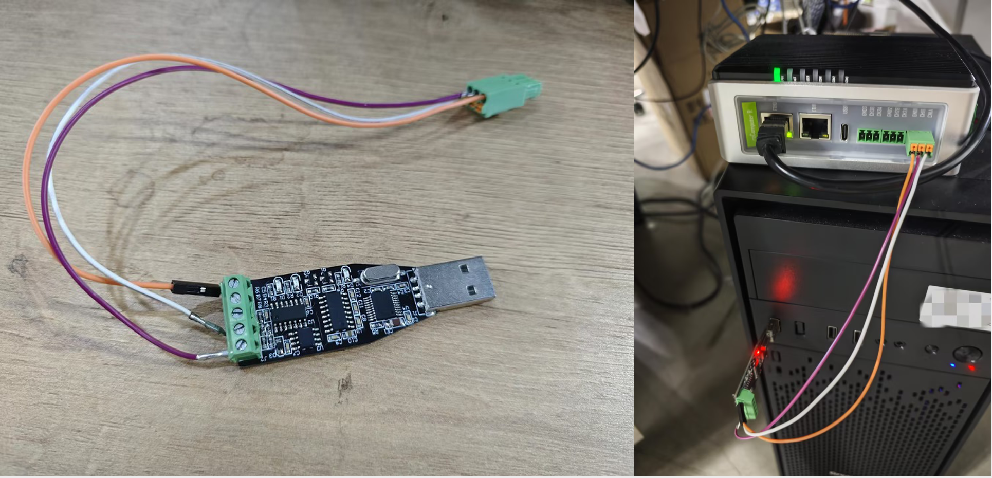
For ModbustRTU, we used an rs485 to USB module to connect the reComuputer R1000 with the W10 pc.
Create New Project
Step 1: Click the Create button in the lower left corner of the homepage, and a new pop-up window will appear. The pop-up window mainly has three attributes that need to be filled in:
- NAME: the name of the new project
- DISPLAY NAME: displayed project name
- DESCRIPTION: description of the project
Step 2: Open the project, enter DB Builder, click Connectors, you can see that there is no Modbus option at this time, we need to open the Modbus Connector of FIN Framwork, then Modbus option will appear here.
Configure Modbus Connector for Modbus TCP
Step 1: Open Modbus Connector. Click Settrings => Ext and find Modbus. At this time, Modbus is marked in red. Click Enable and you can see that the Modbus mark turns green, indicating that the Modbus Connector has been successfully opened. Enter DB Builder again and you can see that there is already a Modbus option.
Step 2: Add a new Modbus connection. Click Modbus => Add, the new pop-up window mainly has the following parameters to fill in:
-
Dis: the name of the connector
-
ModbusSlave: this would be the slave of the modbus device being connected (default is 1)
-
Existing Register Map: If the user already configured a Modbus connector, they would see available registers here to choose from or create a new one with the next property ModbusRegMapUri.
-
ModbusRegMapUri: this is where the user would specify the name of the register map to link with this connector. Replace "xxx" with whatever the name of the register map is.
-
Uri: this is where the uri of the modbus connector would be specified.The format of URI is as shown in the table:
Protocol URI setup Example Notes TCP/IP modbus-tcp://host:port/modbus-tcp://10.0.0.17/Default port is 502, can be omitted if standard RTU over TCP/IP modbus-rtutcp://host:port/modbus-rtutcp://192.168.1.120:9001/Default port is 502, can be omitted if standard RTU over RS-485 modbus-rtu://<port>-<baud>-<dataBits>-<parity>modbus-rtu://serial0-9600-8n1-none
In our example, we specified "r1000_demo" as our register map. Then added our IP to the device in the Uri.
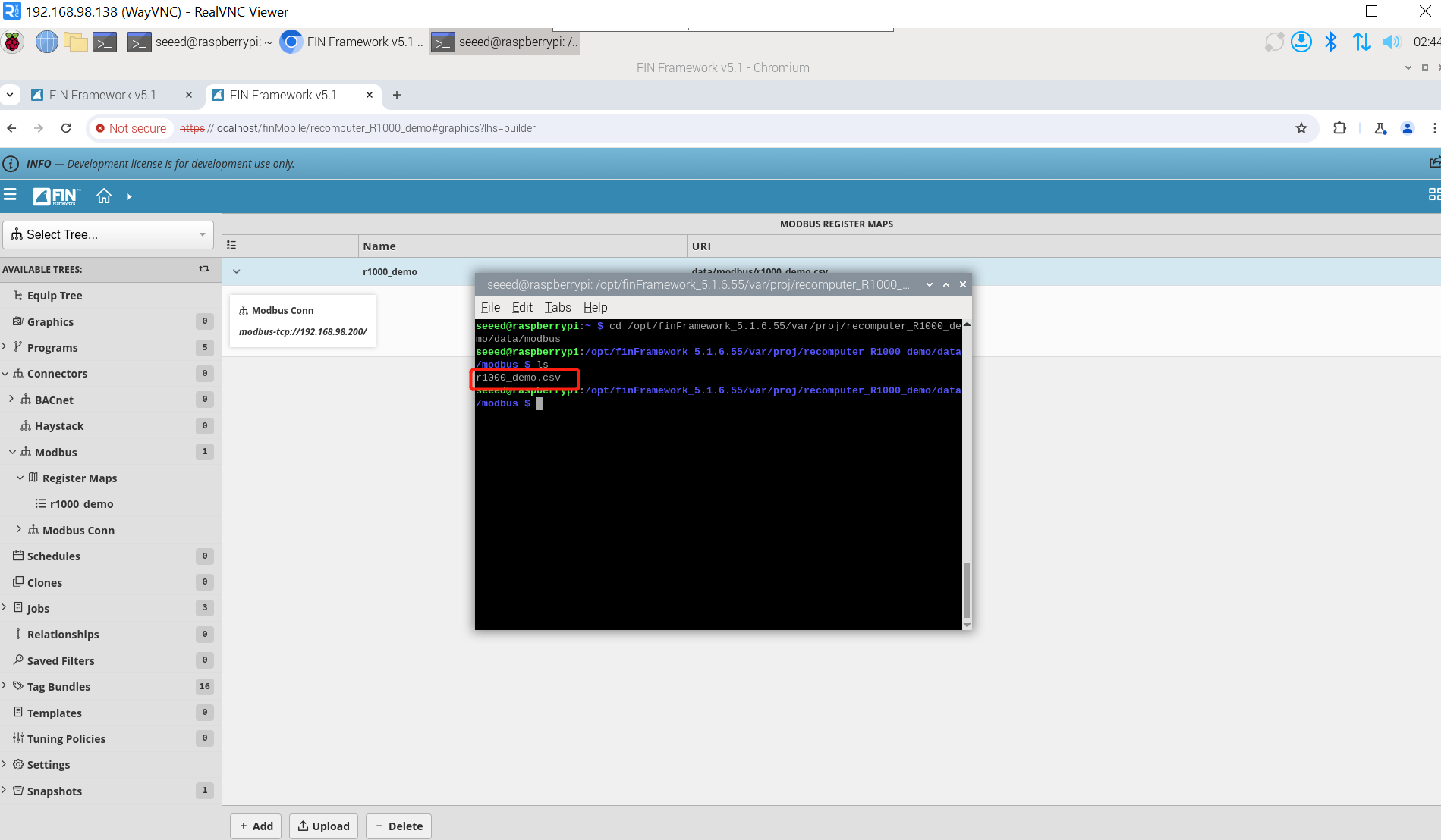
Step 3: Add a new Register Maps. Click Register Maps => Add, enter Name, which needs to be consistent with the name of ModbusRegMapUri in the second step, and finally click ADD.
The system will create a new r1000_demo.csv file in the opt/finFramework_5.1.6.55/var/proj/recomputer_R1000_demo/data/modbus/ directory. This file describes the Modbus register information we need to read.
Step 4: Add the register information to be read. Modbus Connector exists as a Modbus master. It will read the registers of the slave. We need to configure the register information to be read. Click r1000_demo, you can see that there is a description of ping by default, this is a must. We continue to add new register information and click Register Maps => r1000_demo => Add. The new pop-up window mainly has the following parameters to fill in:
-
name(required): name of register.
-
It must be unique
-
It must start with a lower case letter a-z
-
Only a-z, A-Z, 0-9 and underscores are allowed. No spaces or other special characters.
-
-
addr(required): this would be the address of the register that follows the modbus convention.
- 0xxxx - Coil (00001-065536)
- 1xxxx - Discrete Input (10001-165536)
- 3xxxx - Input Register (30001-365536)
- 4xxxx - Holding Register (40001-465536)
-
data(required): this defines the data type of the register.
- Types:
- bit - Bool
- u1 - Unsigned 8-bit Int
- u2 - Unsigned 16-bit Int
- u4 - Unsigned 32-bit Int
- s1 - Signed 8-bit Int
- s2 - Signed 16-bit Int
- s4 - Signed 32-bit Int
- s8 - Signed 64-bit Int
- f4 - 32-bit Float
- f8 - 64-bit Float
- Types:
-
rw(required): this would determine the read/write permissions
- rw - Register may be read and written
- r - Register is read-only
- w - Register is write-only
-
scale(optional): this allows the user to apply a scale factor to the registers. The format is [operator] [number] where the factor is a numeric constant.
- Examples:
- add: +1.5
- minus: -0.25
- mult: *10
- div: /1000
- Examples:
-
dis(optional): this is an optional tag that the user can specify a pretty display name for the register.
-
unit(optional): this would define the unit to use for the register.
-
tags(optional): this would be the tags to apply to the point when learned into the database.
-
folderPath(optional): if the user wants to organize the points, they can do so by applying a folderPath.
Step 5: Communication test. After adding the description information of the register, communication can be carried out. Here we use ModbusMechanic as the Modbus slave. Click Modbus => Ping and you can see that Status changes to OK, indicating that the communication is normal.
Configure Modbus Connector for Modbus RTU
Configure serial port
The script that needs to be executed is as follows:
## Turn off FIN service
sudo systemctl stop fin
## After downloading the config file, place it in /opt/finFramework_5.1.6.55/etc/finStackSerial/
sudo cp ~/config.props  /opt/finFramework_5.1.6.55/etc/finStackSerial/
## Modify the config.props file to: serialPorts=/dev/ttyAMA30, /dev/ttyAMA31, /dev/ttyAMA32
sudo nano /opt/finFramework_5.1.6.55/etc/finStackSerial/config.props
## Restart the FIN service, wait for a while and then use a browser to open FIN
sudo systemctl restart fin
Step 1: Turn off FIN service, then download config file and save it to /opt/finFramework_5.1.6 .55/etc/finStackSerial/ directory
Step 2: Modify config.props to:
serialPorts=/dev/ttyAMA30, /dev/ttyAMA31, /dev/ttyAMA32
After the modification is completed, restart the FIN service

Step 3:Click on Folio => launch,and insert the following query:serialPorts(), The result will show which name has to be used for your specific port.The port is not the name of the physical port, but there is a match between the physical ports of the device and the name of the port to be used like serial0, serial1 ...
Configure Modbus RTU
Step 1: Open Modbus Connector. Click Settrings => Ext and find Modbus. At this time, Modbus is marked in red. Click Enable and you can see that the Modbus mark turns green, indicating that the Modbus Connector has been successfully opened. Enter DB Builder again and you can see that there is already a Modbus option.
Step 2: Add a new Modbus connection. Click Modbus => Add.In our example, we specified "r1000_demo_rtu" as our register map. Then added our serial port to the device in the Uri.
Step 3: Add a new Register Maps. Click Register Maps => Add, enter Name, which needs to be consistent with the name of ModbusRegMapUri in the second step, and finally click ADD.
The system will create a new r1000_demo_rtu.csv file in the opt/finFramework_5.1.6.55/var/proj/recomputer_R1000_demo/data/modbus/ directory. This file describes the Modbus register information we need to read.
Step 4: Add the register information to be read. Modbus Connector exists as a Modbus master. It will read the registers of the slave. We need to configure the register information to be read. Click r1000_demo_rtu, you can see that there is a description of ping by default, this is a must. We continue to add new register information and click Register Maps => r1000_demo_rtu => Add.
Step 5: Communication test. After adding the description information of the register, communication can be carried out. Here we use ModbusMechanic as the Modbus slave. Click Modbus => Ping and you can see that Status changes to OK, indicating that the communication is normal.
Add data points to Equip Tree
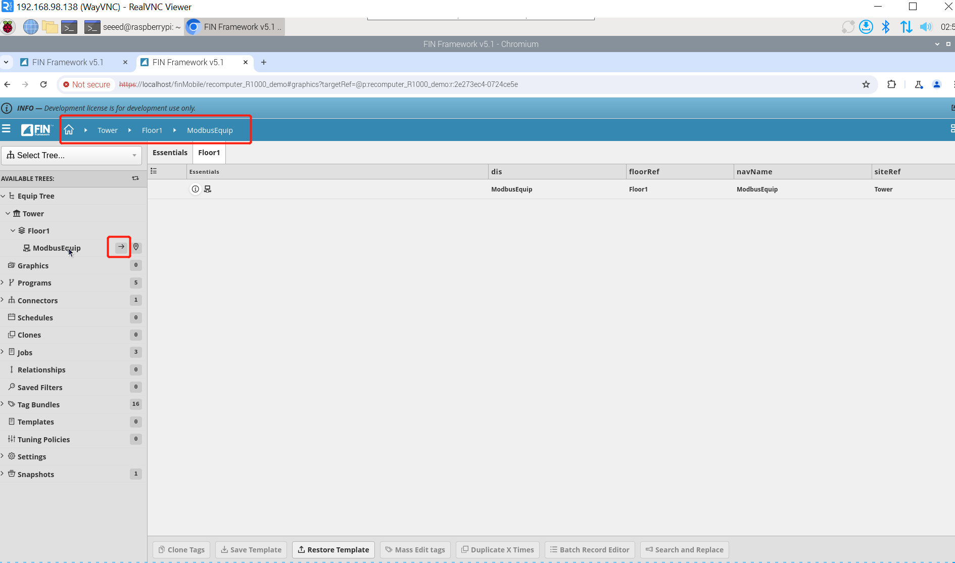
Step 1: add Equip. Click Equip Tree => + => Add site, enter Name, here I enter Tower, it can add a site named Tower; then click Equip Tree => Tower => + => Add Floor, enter Name, here I enter Floor1, it can add a Floor named Floor1; click Equip Tree again => Tower => Floor1 => + => Add Equip, enter Name, here I enter ModbusEquip to add a new Equip.
Step 2: Click -> on the right side of ModbusEquip to make the system path under Tower/Floor1/ModbusEquip.
Step 3: Add data points. Click Modbus => Modbus Conn, click Discover Points in the new window, the register information points we set will appear, select a register to be read, and click Add.
Tech Support & Product Discussion
Thank you for choosing our products! We are here to provide you with different support to ensure that your experience with our products is as smooth as possible. We offer several communication channels to cater to different preferences and needs.