reComputer R1000 with FIN to create a Site Graphic
Introduction
FIN Framework (FIN) is a software framework with application suites that can integrate, control, manage, analyze, visualize and connect. Its capabilities can be integrated by OEMs into a range of products and services.
This article will show you how to use the Graphics Builder of FIN Framwork, and to create a Site Graphic using the Graphics Builder.
Getting Start
Before you start this project, you may need to prepare your hardware and software in advance as described here.
Hardware Preparation
| reComputer R1000 |
|---|
 |
Software Preparation
- Regarding how to install FIN Framwork, you can refer to this wiki.
Steps of create a Site Graphic
Create new Site Graphic
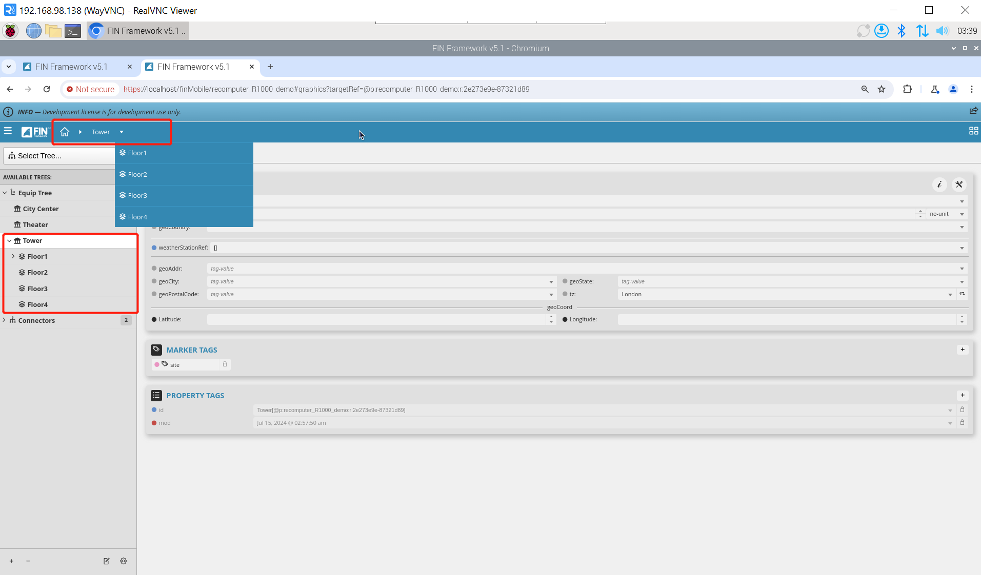
Step 1: We created 4 Floors. For how to create Floors, you can refer to this wiki. Then place the context under the corresponding Site, Here we place it under the Tower path.
Step 2: Create a new Graphic and enter the editing interface. Click Graphic Builder => new, and the pop-up window of Create a Graphic will appear. The difference from creating Top Level Graphic is that the second property here becomes Select floors to include in site graphic, We select all the created Floor and finally click OK. After that, our newly created Graphic will appear on the right side. Click CC Main => Edit to enter the editing interface.
Configure new Site Graphic
Step 1: Import background image. First, select BACGROUND in the property bar in the lower left corner, select TYPE as IMAGE, then import the background image into the workspace, adjust the size and fix it. There are two ways to import background images. The first way is to drag it directly from the folder into the edit box; the second way is to click BROWSE in the lower left corner. If you have imported a certain image before, you can click here find that picture. After importing, right-click the mouse and select Arrange => Send to back to move the image to the bottom layer.
Step 2: Adjust label position. Since we imported 4 Floors, the system automatically generated 4 labels for us. For the sake of beauty, we mapped these labels to the floors one by one.
Step 3: Draw polygons. We use the polygon Tool to draw polygons to mark the position of each Floor.
Step 4: Add Virtual points. Switch to the Virtual points panel on the left, select the virtual point that matches the Floor we selected, and drag it into the drawn polygon.
Step 5: Make the polygon transparent.
Step 6: After saving the settings, we can enter the new Site graphic from Top Level Graphic.
Tech Support & Product Discussion
Thank you for choosing our products! We are here to provide you with different support to ensure that your experience with our products is as smooth as possible. We offer several communication channels to cater to different preferences and needs.