reComputer R1000 with fuxa to use OPC-UA
Introduction
FUXA is a web-based Process Visualization (SCADA/HMI/Dashboard) software. With FUXA you can create modern process visualizations with individual designs for your machines and real-time data display.It supports Modbus RTU/TCP, Siemens S7 Protocol, OPC-UA, BACnet IP, MQTT, and other protocols.
This article mainly introduces how to use fuxa for OPC-UA communication.We run Prosys OPC UA Simulation Server on W10 PC, and then read the data of the simulator on reComputer R1000.
Getting Start
Before you start this project, you may need to prepare your hardware and software in advance as described here.
Hardware Preparation
| reComputer R1000 |
|---|
 |
Software Preparation
- Python 3.11 may be incompatible with fuxa. If your Python version is 3.11, please consider changing to a different Python version.
- Using Prosys OPC UA Simulation Server on W10 PC.You can also use other modbus testing tools
- Using fuxa on reComputer R1000.You can refer to the following steps to install fuxa on reComputer R1000
  ## You need to have installed Node Version 14 || 16 || 18.
  wget https://nodejs.org/dist/v18.20.3/node-v18.20.3-linux-arm64.tar.xz
  tar -xf node-v18.20.3-linux-arm64.tar.xz
  cd node-v18.20.3-linux-arm64
  sudo cp -R * /usr/local/
  node -v
  npm -v
  ## Next install FUXA from npm
  sudo npm install -g --unsafe-perm @frangoteam/fuxa
  sudo fuxa
Hardware Configuration
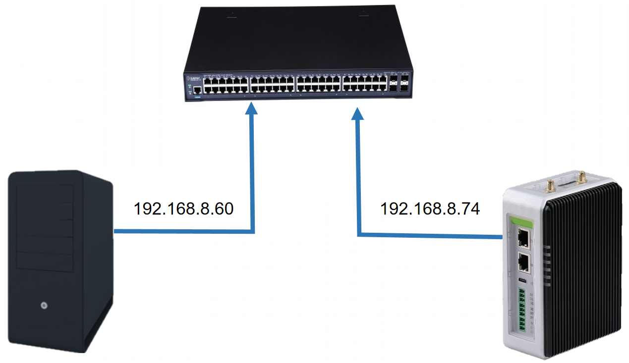
We use Ethernet cables to connect the W10 PC and reComputer R1000 to a switch to ensure that they are on the same network segment.
OPC-UA communication steps
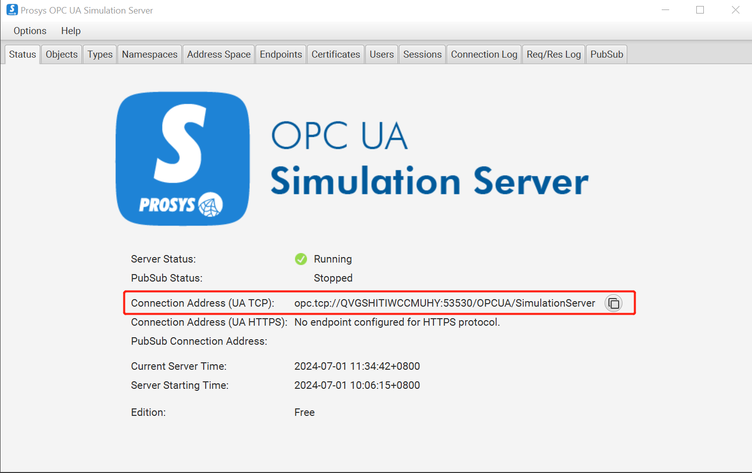
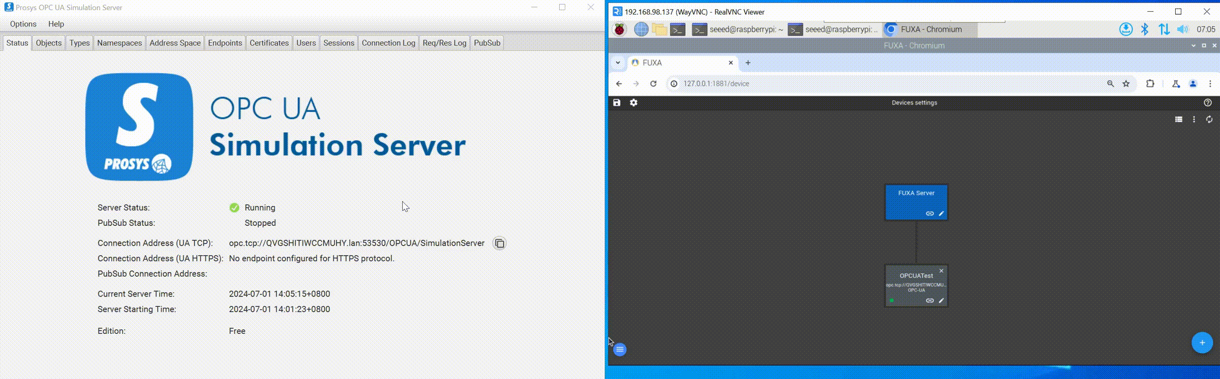
Step 1: Open Prosys OPC UA Simulation Server and copy Connection Address(UA TCP).
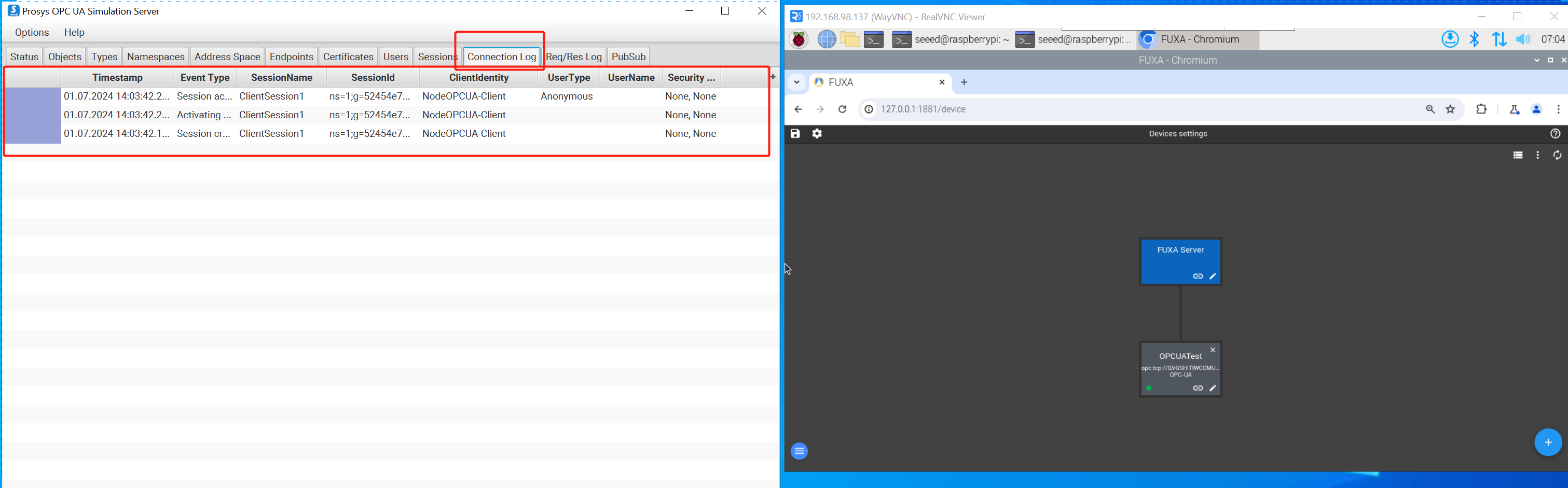
Step 2: Click the + button in the lower right corner, enter Name, select OPCUA for Type, and paste the Connection Address(UA TCP) copied in the first step to Address, Security and encryption mode is selected according to your own device requirements. Here I choose None-None. If your device requires Username and Password when establishing a connection, you can fill in the corresponding places. Finally click OK. Open the ConnectionLog of Prosys OPC UA Simulation Server, and the log as shown in the figure appears, indicating that the connection is successfully established.
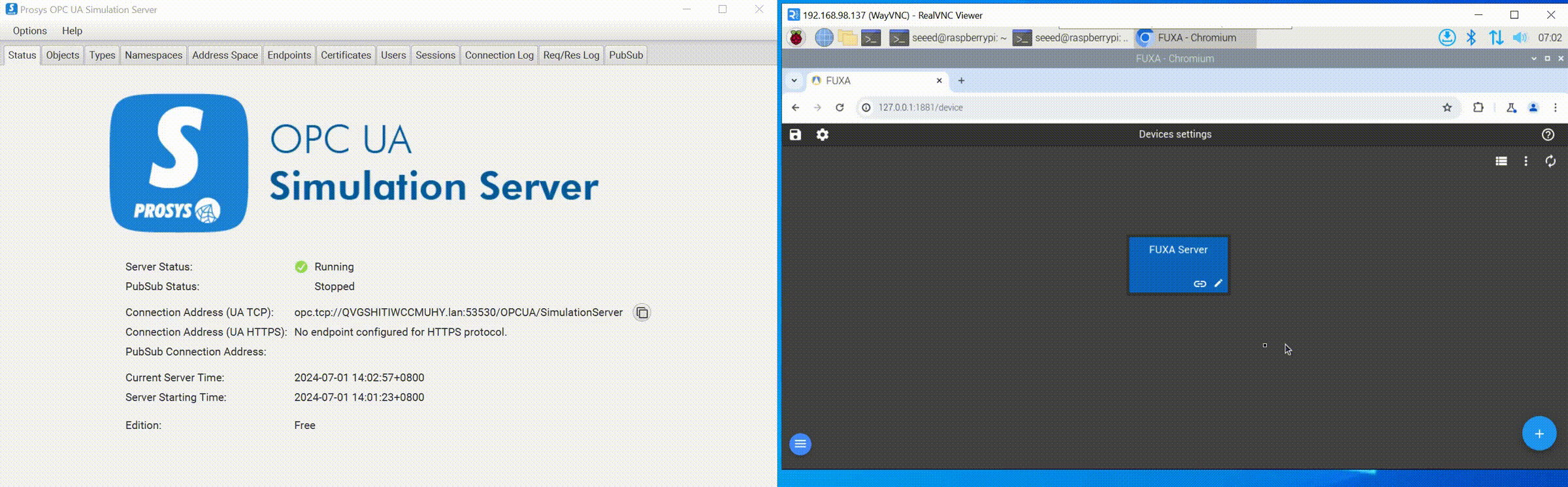
Step 3: Create labels to display data. Enter the configuration interface, click the + button in the upper left corner or lower right corner, you can see the three labels Objects, Type, Views, click Objects, and then click Simulation to see what the simulator simulates For the data, we select all the data under Simulation and create labels. Finally, click OK. You can see that we can try to read the data of the OPCUA device.
Tech Support & Product Discussion
Thank you for choosing our products! We are here to provide you with different support to ensure that your experience with our products is as smooth as possible. We offer several communication channels to cater to different preferences and needs.