Hardware and Interfaces Usage
This wiki introduces the various different hardware and interfaces on the reTerminal and how to use them to expand your project ideas.
Note: For some hardware and interfaces, the usage instructions will be different from each other when running the Raspberry Pi OS image, Buildroot image and the Yocto image. The default steps will be for the Raspberry Pi OS image. However, if the instructions for Buildroot image and the Yocto image are different, they are clearly noted.
Hardware Overview


40-Pin Raspberry Pi Compatible Pins

The 40-pins consist of 26 GPIO, up to 5 × I2C, up to 5 × SPI, up to 5 × UART, 1 x PCM, 1 x PWM, 1 × SDIO interface, 1 × DPI (Parallel RGB Display), up to 3× GPCLK outputs and 1 USB interface.
The USB interface is extended from the internal USB 2.0 interface on the Compute Module 4. So you can expand to even more USB connectors and get speeds up to 480 Mbit/s using this interface.
You can also use these 40 pins to connect to Raspberry Pi compatible Hats and expand your projects!
Visit here to explore a wide range of Raspberry Pi Hats offered by Seeed Studio and visit here to check even more 3rd party Raspberry Pi Hats!
The GPIO pins can draw a maximum current of 50mA safely. This means 50mA distributed across all the pins. Therefore an individual GPIO pin can only safely draw 16mA current. On the other hand, the maximum current draw for each of the remaning pins is 2A. Please keep this in mind when you connect additional hardware to these pins.
Schematics
Tip: Click here for a higher resolution image
Usage - GPIO
- Step 1. Set pin as GPIO
sudo -i   #enable root account privileges
cd /sys/class/gpio
echo 23 > export #GPIO23 which is Pin 16
cd gpio23
- Step 2. Set GPIO input/output
echo in > direction  #set GPIO as input
echo out > direction  #set GPIO as output
- Step 3. Set GPIO high/low level
echo 1 > value  #set GPIO to high
echo 0 > value  #set GPIO to low
- Step 4. Get GPIO input/output status
cat direction
- Step 5. Get GPIO level status
cat value
- Step 6. Set pin back to default
cd ..
echo 23 > unexport
Usage on Buildroot image
- Replace sudo -i with su - to enable root account privileges
- Follow the other steps as mentioned above
Usage on Yocto image
- sudo -i is not needed because we already log in as root
- Follow the other steps as mentioned above
Usage - I2C
-
Step 1. Turn on the reTerminal, click on the Raspberry Pi icon on Raspberry Pi Desktop UI and navigate to
Preferences > Raspberry Pi Configuration -
Step 2. Click on the
Interfacestab and click on Enabled which is next to I2C

-
Step 3. Click OK
-
Step 4. Connect an I2C device to the reTerminal
-
Step 5. List all the available I2C busses
i2cdetect -l

- Step 6. Scan the standard addresses on I2C bus 1 (i2c-1)
i2cdetect -y 1
Note 1 represents the I2C bus number

The above picture shows I2C devices detected with addresses 0x20, 0x51, 0x45, 0x19, 0x29 and 0x5c
Usage on Buildroot image
- You don't need to turn on I2C for the Buildroot image because I2C is enabled by default
- Follow the other steps as mentioned above
Usage on Yocto image
- I2C is not enabled when turned on. It only works with modprobe i2c-dev after each boot. This will be updated once it is fixed.
Usage - SPI
-
Step 1. Turn on the reTerminal, click on the Raspberry Pi icon on Raspberry Pi Desktop UI and navigate to
Preferences > Raspberry Pi Configuration -
Step 2. Click on the
Interfacestab and click on Enabled which is next to SPI

-
Step 3. Connect an SPI device to the reTerminal
-
Step 4. List all the available SPI devices
ls /dev/spi*
You will see the following output

- Step 5. Open a terminal window and type the following to download an SPI test tool
wget https://files.seeedstudio.com/wiki/102110497/spidev_test
- Step 6. Change the user rights of the tool
chmod +x spidev_test
- Step 7. Short GPIO 10 (Pin 19) and GPIO 9 (Pin 21) using a jumper wire
Note: Here we short-circuit MOSI and MISO pins
- Step 8. Run the the following SPI test tool
./spidev_test -D /dev/spidev0.0 -v -p hello
If you see the following output, SPI is working properly

Usage on Buildroot/ Yocto image
- To turn on SPI, open config.txt by vi /boot/config.txt command
- Add dtparam=spi=on at the end (press i to enter edit mode)
- Press ESC to quit from edit mode
- Save the file by typing :wq
- Reboot
- spidev_test tool has problem when running. This will be updated once it is fixed.
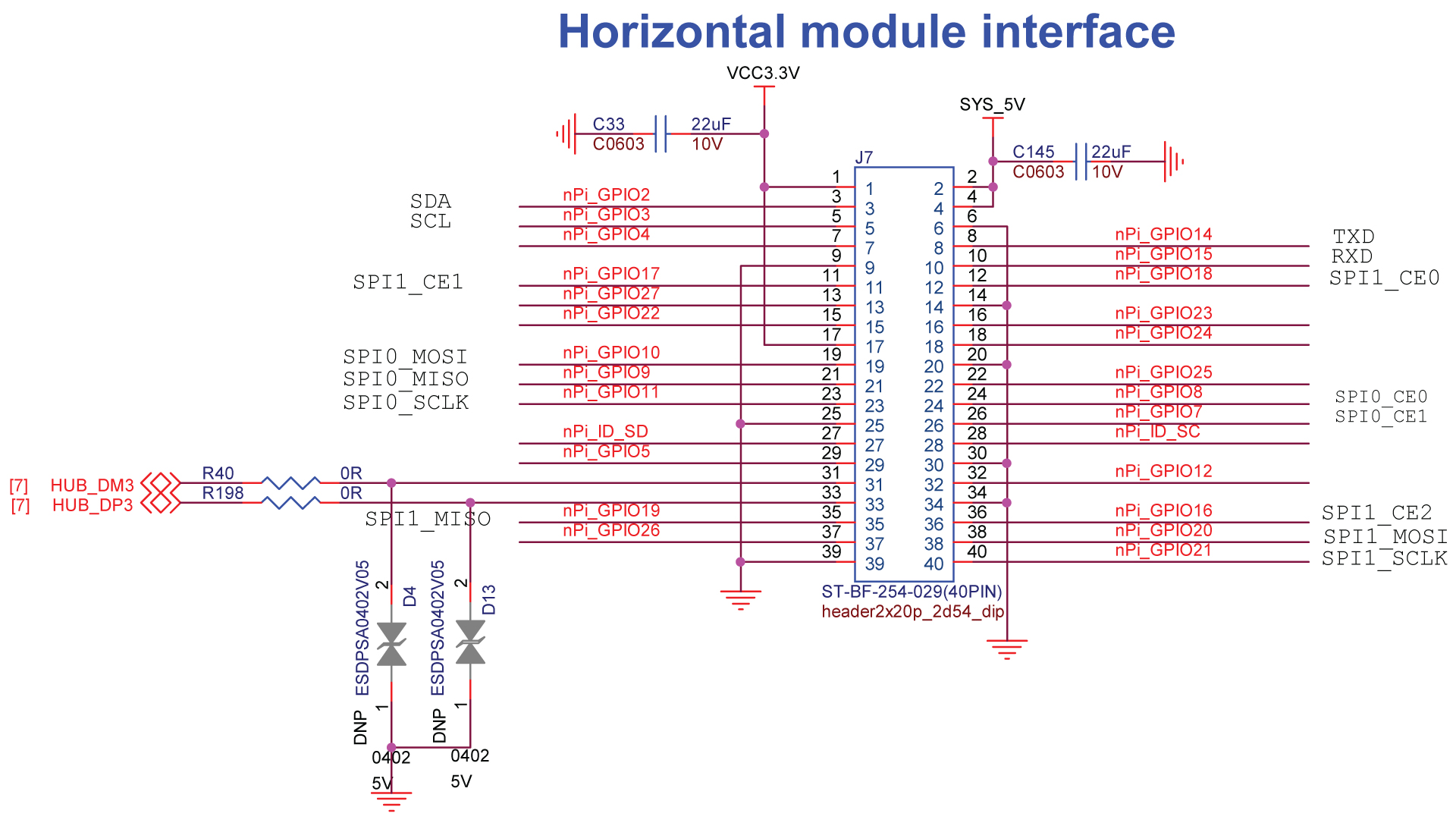
High-Speed Interface for Expansion Modules
There is a high-speed expansion interface at the back of the reTerminal. It consists of 1 PCIe 1-lane Host Gen 2 (supporting speeds up to 5Gbps), 1 USB 2.0, 1 PoE and 26 GPIOs. The 26 GPIO pins can be further used as 2 I2C, 2 SPI and 1 UART.

Tip: Click here for a higher resolution image
PCIe, USB 3.0, 2 x CAN-FD and SDIO3.0 interfaces are defined for future products and therefore they are not usable at the moment
We plan to build expansion modules in the future for reTerminal and we have reserved this interface to connect these modules to the reTerminal. We will release a wide range of modules such as:
- Mic Array & Speaker Module
- Camera Module
- Industrial I/O
- LoraWAN Module
- 5G/4G Module
- PoE Module
- Ethernet Switch

There are 2 x M4 mechanical screw holes on the side of the reTerminal to help keep the expansion modules in place.
CSI Camera Interface
reTerminal has a 2-lane MIPI CSI camera interface, which means you can connect up to 2 cameras to the reTerminal. One interface has 15 pins whereas the other interface has 22 pins. So make sure to use the correct flex cable corresponding to the interface that you intend to use. These camera interfaces can be used for object detection and machine learning applications.
Schematics

Tip: Click here for a higher resolution image
Usage
- Step 1. Connect a camera to the 15 pins or 22 pins FPC interface

-
Step 2. Turn on the reTerminal, click on the Raspberry Pi icon on Raspberry Pi Desktop UI and navigate to
Preferences > Raspberry Pi Configuration -
Step 3. Click on the
Interfacestab and click on Enabled which is next to Camera

- Step 4. Click Yes to reboot

- Step 5. Open a terminal window and type the following to take a still picture and save it to the Desktop
raspistill -o Desktop/image.jpg
Note: You can change the save location according to your preference
-
Step 6. Double click on the file generated on the Desktop to view the image
-
Step 7. Type the following to record a video and save it to the Desktop
raspivid -o Desktop/video.h264
- Step 8. Double click on the file generated on the Desktop to play the recorded video
You can learn more about camera usage by visiting official Raspberry Pi documentation
Usage on Buildroot/ Yocto image
- The CSI camera interface is not tested yet. This will be updated once it is tested.
5-Inch LCD
The inbuilt 5-inch LCD on the reTerminal is connected to the 30-pin DSI interface on the carrier board inside. This LCD supports 5-point multi-touch and in order to enable this feature, the LCD is connected to another TP interface on the carrier board.
Schematics

Tip: Click here for a higher resolution image
Touch Panel for LCD
Usage
The touch panel for the LCD is connected via a 6-pin FPC connector. You can test it by using the evtest tool
- Step 1. Type the following to install evtest, which is an input device event monitor and query tool
sudo apt install evtest
- Step 2. Open the evtest tool
evtest

- Step 3. Type 1 and you will see following output

- Step 4. Touch randomly on the reTerminal LCD and you will see the following output

Usage on Buildroot image
- You don't need to install evtest tool because it is already installed
- Before running evtest you need to change to root by typing su -
- Follow the other steps as mentioned above
Usage on Yocto image
- You don't need to install evtest tool because it is already installed
- Follow the other steps as mentioned above
Connect other devices to FPC connector via I2C
The touch panel is connected to the reTerminal via I2C communication protocol. So you can easily connect other I2C devices to this 6-pin FPC interface if you prefer. The connection diagram is as follows

After that follow the steps from the previous topic on how to use I2C
4 User Programmable Buttons
There are 4 user programmable buttons at the front of the reTerminal. These buttons can be easily controlled using software and can be assigned to switch ON/OFF different functions according to your applications!
Schematics

Tip: Click here for a higher resolution image
Usage

- Step 1. Open the evtest tool
evtest

- Step 2. Type 0 and you will see following output

- Step 3. Press the buttons from left to right and you will see the following

Note: The buttons are configured as a s d f from left to right by default
- Step 4. If you want to configure the buttons, type the following
sudo nano /boot/config.txt
- Step 5. Modify the file by adding the following to the end
dtoverlay=reTerminal,key0=0x100,key1=0x101,key2=0x102,key3=0x103,tp_rotate=1
Note: Here the hexadecimal numbers 100,101,102 and 103 are assigned to key0, key1, key2. key3 respectively
Usage on Buildroot image
- You don't need to install evtest tool because it is already installed
- Before running evtest you need to change to root by typing su -
- Follow the other steps as mentioned above
Usage on Yocto image
- You don't need to install evtest tool because it is already installed
- Follow the other steps as mentioned above
3 User Programmable LEDs
There are 2 user programmable LEDs at the front of the reTerminal. These LEDs can be switched ON/OFF using software and can be useful in scenarios where you want to use them as status LEDs to monitor different hardware features. The USR LED can be lighted up Green, wheras the STA LED can be lighted up either Red or Green
Schematics

Tip: Click here for a higher resolution image
Usage

- Step 1. Enable root account privileges
sudo -i
- Step 2. Enter the following directory
cd /sys/class/leds
- Step 3. Enter the following directory to control the Green Color USR LED
cd usr_led0
- Step 4. Turn on the LED with maximum brightness
echo 255 > brightness
Note: You can enter values from 1 - 255 to adjust the brightness levels
- Step 5. Turn off the LED
echo 0 > brightness
- Step 6. Enter the following directory to control the Red Color STA LED
cd ..
cd usr_led1
-
Step 7. Repeat steps 4 - 5 to control the LED
-
Step 8. Enter the following directory to control the Green Color STA LED
cd ..
cd usr_led2
- Step 9. Repeat steps 4 - 5 to control the LED
Usage on Buildroot image
- Replace sudo -i with su - to enable root account privileges
- Follow the other steps as mentioned above
Usage on Yocto image
- sudo -i is not needed because we already log in as root
- Follow the other steps as mentioned above
Gigabit Ethernet Port
reTerminal has a Gigabit Ethernet Connector (RJ45) onboard. This port is connected to the Gigabit Ethernet PHY of the CM4 module which is based on Broadcom BCM54210PE. It is also IEEE 1588-2008 compliant.
Schematics

Tip: Click here for a higher resolution image
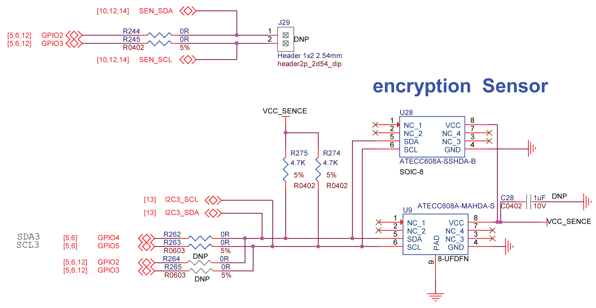
Encryption Co-Processor
reTerminal has security features such as a Microchip ATECC608A cryptographic co-processor with secure hardware-based key storage. It also has protected storage for up to 16 keys, certificates, or data. It provides hardware support for symmetric sign, verify, key agreement – ECDSA. It has hardware support for symmetric algorithms, networking key management and secure boot.
Schematics
Tip: Click here for a higher resolution image
Usage
- Step 1. List all the available I2C busses
i2cdetect -l
- Step 2. Scan the standard addresses on I2C bus 3 (i2c-3)
i2cdetect -y 3

Note: 3 represents the I2C bus number
The device with I2C address 0x60 is the encryption co-processor
Usage on Buildroot image
- Works as above
Usage on Yocto image
- I2C is not enabled when turned on. It only works with modprobe i2c-dev after each boot. This will be updated once it is fixed.
RTC
The in-built RTC on the reTerminal is based on NXP Semiconductors PCF8563T and uses a CR1220 battery to power it on. It has a low backup current; typical 0.25μA at VDD = 3.0 V and a temperature = 25°C. It can be used for projects where you need to implement time keeping functions.
Note: A CR1220 battery is already installed out-of-the-box.
Schematics

Tip: Click here for a higher resolution image
Usage
Type the following command to obtain the date and time information from the RTC
sudo hwclock

Usage on Buildroot image
- First type su - to enable root account
- Then type hwclock
Usage on Yocto image
- sudo is not needed because we already log in as root
- Just type hwclock
Light Sensor
reTerminal is quipped with a Levelek LTR-303ALS-01 digital light sensor and it is connected to the 6-pin FPC interface. It can be used to sense the light levels in the environment and also can be used for automatic brightness adjustment of LCD backlight according to the surrounding light levels.
Schematics

Tip: Click here for a higher resolution image
Usage
- Step 1. Enable root account privileges
sudo -i
- Step 2. Enter the following directory
cd /sys/bus/iio/devices/iio:device0
- Step 3. Type the following to obtain the light intensity value in Lux
cat in_illuminance_input

The light sensor is connected to the reTerminal via I2C communication protocol. So you can easily connect other I2C devices to this 6-pin FPC interface if you prefer. The connection diagram is as follows

After that follow the steps from the previous topic on how to use I2C
Usage on Buildroot image
- Replace sudo -i with su - to enable root account privileges
- Follow the other steps as mentioned above
Usage on Yocto image
- sudo -i is not needed because we already log in as root
- Follow the other steps as mentioned above
Accelerometer
The in-built STMicroelectronics LIS3DHTR 3-axis accelerometer can be used to realize many different applications with the reTerminal. You can use it to automatically change screen orientation as you rotate the reTerminal and much more.
Schematics

Tip: Click here for a higher resolution image
Usage
- Step 1. Open the evtest tool
evtest
- Step 2. Type 1 and you will see the X,Y,Z acceleration values

Usage on Buildroot image
- You don't need to install evtest tool because it is already installed
- Before running evtest you need to change to root by typing su -
- Follow the other steps as mentioned above
Usage on Yocto image
- You don't need to install evtest tool because it is already installed
- Follow the other steps as mentioned above
Buzzer
There is a built-in buzzer on the reTerminal. This can be controlled using software. This buzzer can be used as an indicator in different applications.
Schematics

Tip: Click here for a higher resolution image
Usage
- Step 1. Enable root account privileges
sudo -i
- Step 2. Enter the following directory
cd /sys/class/leds/usr_buzzer
- Step 3. Turn on the buzzer
echo 1 > brightness
- Step 4. Turn off the buzzer
echo 0 > brightness
Usage on Buildroot image
- Replace sudo -i with su - to enable root account privileges
- Follow the other steps as mentioned above
Usage on Yocto image
- sudo -i is not needed because we already log in as root
- Follow the other steps as mentioned
USB 2.0 Ports
Raspberry Pi CM4 already has a USB 2.0 Hub onboard. This Hub is extended to 2 USB 2.0 Ports on the reTerminal as USB HOST
Schematics

Tip: Click here for a higher resolution image
Usage
- Step 1. Connect a USB device to one of the USB 2.0 ports on the reTerminal

- Step 2. List the connected USB device by typing the following in a terminal window
lsusb

- Step 3. Type the following to gather more information about the connected USB device such as the drive size, partitions, mount point, etc
lsblk

- Step 4. Access the connected USB device and list all the files inside
cd /media/pi/NEW VOLUME
ls -l

Note: The mount point will change from USB device to USB device
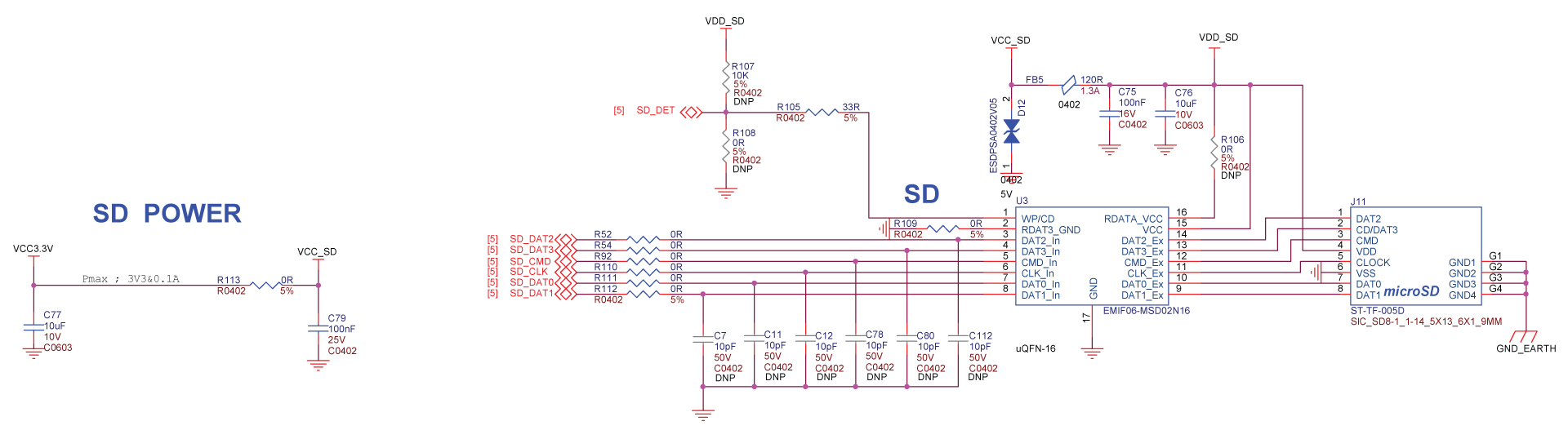
Micro - SD Card Slot
reTerminal is equipped with a micro-sd card slot. This is useful when you want to install the operating system on to a micro-SD card, while the CM4 module without eMMC is used. It is recommeded to use a card with a minimum of at least 8GB. Follow this link to learn more!
Schematics
Tip: Click here for a higher resolution image
Micro HDMI Port
There is a micro HDMI port on the reTerminal and you can use it to connect to HDMI displays via a micro HDMI to standard HDMI cable. It supports up to 4K resolution at 60fps.
Schematics

Tip: Click here for a higher resolution image
Usage
- Step 1. Connect an HDMI display to the micro-HDMI port of the reTerminal using a micro-HDMI to standard-HDMI cable

- Step 2. Turn on the reTerminal and you will see the UI output on both reTerminal LCD and the connected HDMI display
Note: If you connect a display while the reTerminal is powered on, you need to type sudo service lightdm restart to display the UI on the connected HDMI display.
- Step 3. Type the following in a terminal window to install Screen Configuration utility
sudo apt install arandr
- Step 4. Click on the Raspberry Pi icon on the top left corner and navigate to
Preferences > Screen Configuration

- Step 5. Inside the Screen Layout Editor window, navigate to
Configure > Screens > HDMI-1 > Resolutionand adjust select the resolution of the connected HDMI display.

Note: You can also change the frequency and the orientation of the display
- Step 6. Drag the two boxes to change the arrangement of the displays.

- Step 7. Click on the tick mark to apply the settings

Usage on Buildroot/ Yocto image
- Hot-plug doesn’t work at the moment. This will be updated once it is fixed.
- So you need to first connect to HDMI display and then turn on reTerminal
- Note that arandr package is not available for Buildroot system image
USB Type-C Port
The USB Type-C Port on the reTerminal can be used to power the reTerminal using 5V/4A (recommended). However it can also be used to act as a USB Device where you can connect the reTerminal to a HOST PC and the reTerminal will act as a USB Mass Storage Device. In here, you will be able to access the onboard eMMC of the reTerminal via a PC and flash an operating system to the eMMC. Click here to learn more!

Standard Camera Mount (1/4 inch)
reTerminal has a standard camera mount with a diameter of 1/4 inch. So you can connect the reTerminal to a standard tripod.

Python Library for reTerminal
We have prepared a Python library which enables you to use the onboard hardware on the reTerminal. Currently the accelerometer, user LEDs, user buttons and buzzer can be accessed using this Python library.
Installation
Open a terminal window on the reTerminal and execute the following
sudo pip3 install seeed-python-reterminal
Note: The source code can be found here
Usage
- Step 1. Create a new python file and open using nano text editor
nano test.py
-
Step 2. Enter the python codes
-
Step 3. Press CTRL + X and then press Y to save the file
-
Step 4. Finally run the file
python3 test.py
You can follow the above steps to test for the below hardware functions. The included Python codes under each section can be directly entered into the test.py file and then execute the file
User LEDs Test
import seeed_python_reterminal.core as rt
import time

print("STA ON, USR OFF")
rt.sta_led = True
rt.usr_led = False
time.sleep(1)

print("STA OFF, USR ON")
rt.sta_led = False
rt.usr_led = True
time.sleep(1)

print("STA RED, USR OFF")
rt.sta_led_green = False
rt.sta_led_red = True
rt.usr_led = False
time.sleep(1)

print("STA OFF, USR OFF")
rt.sta_led = False
rt.usr_led = False
Buzzer Test
import seeed_python_reterminal.core as rt
import time

print("BUZZER ON")
rt.buzzer = True
time.sleep(1)

print("BUZZER OFF")
rt.buzzer = False
User Buttons Test
import seeed_python_reterminal.core as rt
import seeed_python_reterminal.button as rt_btn


device = rt.get_button_device()
while True:
    for event in device.read_loop():
        buttonEvent = rt_btn.ButtonEvent(event)
        if buttonEvent.name != None:
            print(f"name={str(buttonEvent.name)} value={buttonEvent.value}")
Accelerometer Test
import seeed_python_reterminal.core as rt
import seeed_python_reterminal.acceleration as rt_accel


device = rt.get_acceleration_device()
while True:
    for event in device.read_loop():
        accelEvent = rt_accel.AccelerationEvent(event)
        if accelEvent.name != None:
            print(f"name={str(accelEvent.name)} value={accelEvent.value}")
Accelerometer and Buttons Test
import asyncio
import seeed_python_reterminal.core as rt
import seeed_python_reterminal.acceleration as rt_accel
import seeed_python_reterminal.button as rt_btn


async def accel_coroutine(device):
    async for event in device.async_read_loop():
        accelEvent = rt_accel.AccelerationEvent(event)
        if accelEvent.name != None:
            print(f"accel name={str(accelEvent.name)} value={accelEvent.value}")


async def btn_coroutine(device):
    async for event in device.async_read_loop():
        buttonEvent = rt_btn.ButtonEvent(event)
        if buttonEvent.name != None:
            print(f"name={str(buttonEvent.name)} value={buttonEvent.value}")


accel_device = rt.get_acceleration_device()
btn_device = rt.get_button_device()

asyncio.ensure_future(accel_coroutine(accel_device))
asyncio.ensure_future(btn_coroutine(btn_device))

loop = asyncio.get_event_loop()
loop.run_forever()
Usage on Buildroot image
- This library will be added later to the Buildroot image
- First type su - to enable root account
- The type pip3 install seeed-python-reterminal
- use vi as text editor when creating the Python files
- Accel + button demo has a problem. This will be updated once it is fixed
Usage on Yocto image
- Eventhough Python is installed, pip is not installed. We will later pack this library inside this system image
Tech Support & Product Discussion
Thank you for choosing our products! We are here to provide you with different support to ensure that your experience with our products is as smooth as possible. We offer several communication channels to cater to different preferences and needs.