Getting Started with reTerminal E10-1
Materials Required
| reTerminal | reTerminal E10-1 |
|---|---|
 |  |
| Get ONE Now | Get ONE Now |
Preliminary Preparation
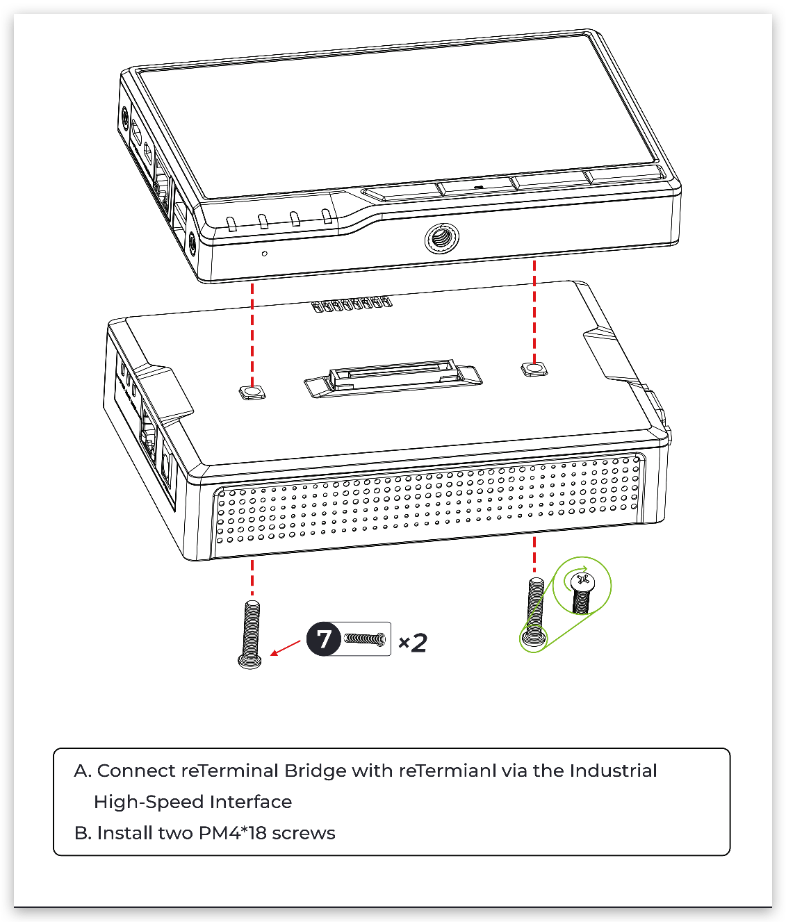
Connection
Note the orientation and place the reTerminal on the reTerminal E10-1, and force them to fit snugly. If the reTerminal E10-1 is powered on at this time, reTerminal will wake up and boot into the system. If you want to know more about reTerminal, please click reTerminal.
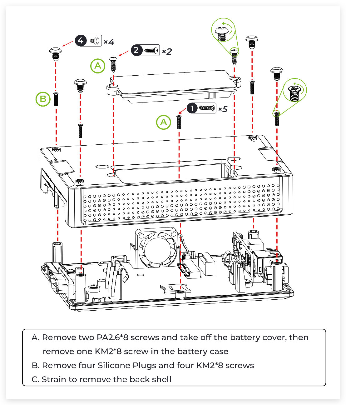
Installation and removal
In the process of using the reTerminal E10-1, it may be necessary to remove its casing to add peripherals.
Driver Installation
If you want reTerminal to use the functions of reTerminal E10-1, you need to install the driver for reTerminal before starting. Please follow the commands in the terminal window of reTerminal.
git clone https://github.com/Seeed-Studio/seeed-linux-dtoverlays.git
cd seeed-linux-dtoverlays
sudo ./scripts/reTerminal.sh
For 32bit OS you will need to add following step before execute sudo ./scripts/reTerminal.sh
echo arm_64bit=0 | sudo tee -a /boot/config.txt
After the installation is complete, please restart the machine. Then use the following command to check whether the reTerminal-bridge.dtbo file exists to ensure that the driver installation is complete.
ls /boot/overlays/reTerminal-bridge.dtbo

Install Libraries
Install the python3 library.
sudo apt-get update
sudo apt-get install python3-pip
sudo pip3 install RPi.GPIO
sudo apt-get install python3-serial
Install the git library.
sudo apt install -y git
Power Supply
There are three methods to supply power shown as below:
- DC Jack
- PoE
- UPS -18650 battery
The battery for this device is NCR18650B chargeable Li-ion battery. Please kindly know that no battery in the package, while the battery is available in regular convenience store and customer need to prepare themselves. And what we propose is Panasonic NCR18650B 3.6V 3400mAh.
DC Jack
Supply power to the reTerminal, the expansion board and the battery in DC 12V @4A
PoE
The PoE power input is RJ45 and supports a maximum of 25W power input.
UPS -18650 battery
2 x battery holder with fixed pin.
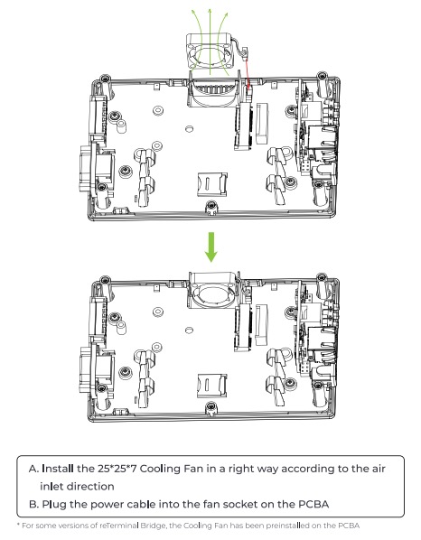
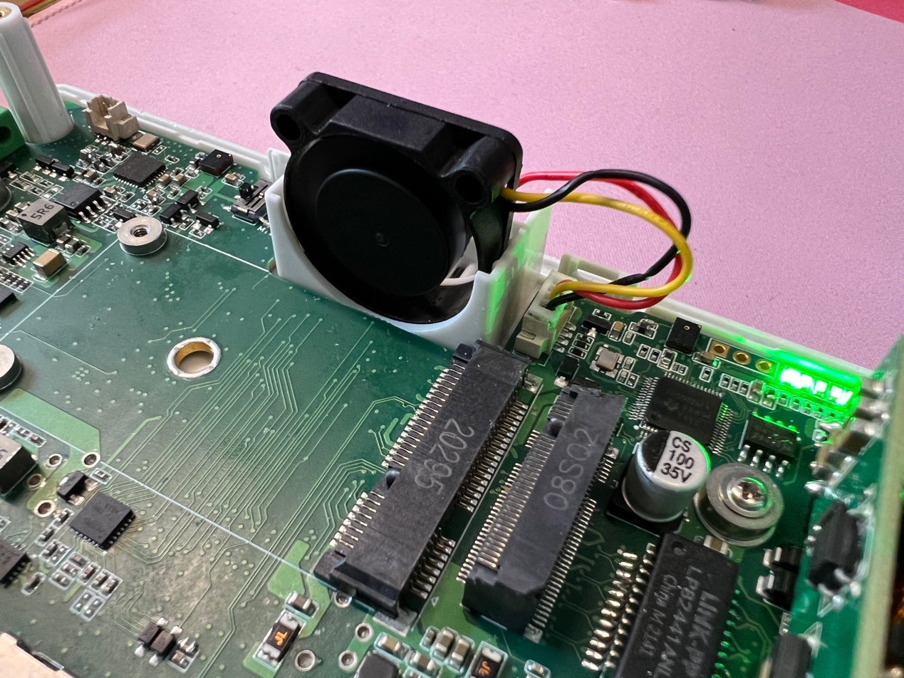
Fan
Materials required
- reTerminal x1
- reTerminal E10-1 x1
- Fan(inlcuded) x1
In order to keep the reTerminal and reTerminal E10-1 at a normal temperature level under heavy load. There is a 3-Pin fan inside the reTerminal E10-1.
This example introduces how to control fan on reTerminal E10-1.
Step 1. We can directly control the fan switch by the following command.
#Toggle fan on
raspi-gpio set 23 op pn dh

#Toggle fan off
raspi-gpio set 23 op pn dl
Step 2. We can also enable and disable the fan by detecting the temperature of the CPU. Please follow the steps below to download and run the program.
git clone https://github.com/limengdu/Seeed_reTerminal_Bridge_Fan_control.git
cd Seeed_reTerminal_Bridge_Fan_control/
sudo python3 fan.py
Here is the fan.py code for reference.
import sys
import time
try:
 import RPi.GPIO as GPIO
except RuntimeError:
 print("Error importting Rpi.GPIO")

MAX_TEMP = 40.0
MIN_TEMP = 20.0

def cpu_temp():
 f = open("/sys/class/thermal/thermal_zone0/temp",'r')
 return float(f.read())/1000

def main():
 channel = 23
 GPIO.setmode(GPIO.BCM)

 # init 23 off
 GPIO.setup(channel,GPIO.OUT,initial=GPIO.LOW)
 is_close = True
 while 1:
  temp = cpu_temp()
  if is_close:
   if temp > MAX_TEMP:
    GPIO.output(channel,GPIO.HIGH)
    is_close = False
  else:
   if temp < MIN_TEMP:
    GPIO.output(channel,GPIO.LOW)
    is_close = True
  time.sleep(2.0)
  GPIO.setwarnings(False)

if __name__ == '__main__':
 main()
After the code runs successfully, when the CPU temperature is detected to be higher than 40°C, the fan will be turned on. When the temperature is lower than 20°C, the fan will be turned off.
CAN Communication
A Controller Area Network (CAN) is a robust vehicle bus standard designed to allow microcontrollers and devices to communicate with each other's applications without a host computer.
Materials required
- reTerminal x2
- reTerminal E10-1 x2
- male to male cable x2
This example introduces how to use the CAN on the reTerminal E10-1.
Step 1. Use male to male cables to connect the two reTerminal E10-1s through the CAN interface.
H -> H L -> L GND -> GND
Step 2. Install the CAN-utils separately for the two reTerminals.
sudo apt install can-utils
CAN-utils is a collection of extremely useful debugging tools using the CAN interface. It includes applications such as:
- candump – Dump can packets – display, filter and log to disk.
- canplayer – Replay CAN log files.
- cansend – Send a single frame.
- cangen – Generate random traffic.
- canbusload – display the current CAN bus utilisation.
CAN-utils source can be obtained from the GitHub repository.
Step 3. Add configuration information for two reTerminals. Open the /boot/config.txt file with an editor and save it after adding dtoverlay=seeed-can-fd-hat-v2 at the end, then restart reTerminal.
Without an ID EEPROM on the ‘hat’ specifying the hardware, the Linux kernel will not automatically discover the CAN Controller on the SPI interface. To load the appropriate driver, you must specify device tree overlay settings at boot.
sudo nano /boot/config.txt
Step 4. The CAN interface behaves just like a network interface. You should be able to get various statistics using ifconfig -a (interface configuration).
Use the command cangen can0 -v to send random data to test if the CAN communication goes well.
Step 5. You can manually bring up the CAN interface using:
sudo ip link set can0 up type can bitrate 500000
Step 6. Download the code to reTerminal.
git clone https://github.com/limengdu/Seeed_reTerminal_Bridge_CAN_exmaple
One of the reTerminals compiles and runs the code that sends the data.
cd Seeed_reTerminal_Bridge_CAN_exmaple/
gcc cantransmit.c -o cantransmit
Here is the cantransmit.c code for reference.
#include <stdio.h>
#include <stdlib.h>
#include <string.h>
#include <unistd.h>

#include <net/if.h>
#include <sys/ioctl.h>
#include <sys/socket.h>

#include <linux/can.h>
#include <linux/can/raw.h>

int main(int argc, char **argv)
{
 int s;
 struct sockaddr_can addr;
 struct ifreq ifr;
 struct can_frame frame;

 printf("CAN Sockets Demo\r\n");

 if ((s = socket(PF_CAN, SOCK_RAW, CAN_RAW)) < 0) {
  perror("Socket");
  return 1;
 }

 strcpy(ifr.ifr_name, "can0" );
 ioctl(s, SIOCGIFINDEX, &ifr);

 memset(&addr, 0, sizeof(addr));
 addr.can_family = AF_CAN;
 addr.can_ifindex = ifr.ifr_ifindex;

 if (bind(s, (struct sockaddr *)&addr, sizeof(addr)) < 0) {
  perror("Bind");
  return 1;
 }

 frame.can_id = 0x555;
 frame.can_dlc = 5;
 sprintf(frame.data, "Hello");

 if (write(s, &frame, sizeof(struct can_frame)) != sizeof(struct can_frame)) {
  perror("Write");
  return 1;
 }

 if (close(s) < 0) {
  perror("Close");
  return 1;
 }

 return 0;
}
Another reTerminal compiles and runs the code that receives the data.
gcc canreceive.c -o canreceive
Here is the canreceive.c code for reference.
#include <stdio.h>
#include <stdlib.h>
#include <string.h>
#include <unistd.h>

#include <net/if.h>
#include <sys/ioctl.h>
#include <sys/socket.h>

#include <linux/can.h>
#include <linux/can/raw.h>

int main(int argc, char **argv)
{
 int s, i;
 int nbytes;
 struct sockaddr_can addr;
 struct ifreq ifr;
 struct can_frame frame;

 printf("CAN Sockets Receive Demo\r\n");

 if ((s = socket(PF_CAN, SOCK_RAW, CAN_RAW)) < 0) {
  perror("Socket");
  return 1;
 }

 strcpy(ifr.ifr_name, "can0" );
 ioctl(s, SIOCGIFINDEX, &ifr);

 memset(&addr, 0, sizeof(addr));
 addr.can_family = AF_CAN;
 addr.can_ifindex = ifr.ifr_ifindex;

 if (bind(s, (struct sockaddr *)&addr, sizeof(addr)) < 0) {
  perror("Bind");
  return 1;
 }

 nbytes = read(s, &frame, sizeof(struct can_frame));

  if (nbytes < 0) {
  perror("Read");
  return 1;
 }

 printf("0x%03X [%d] ",frame.can_id, frame.can_dlc);

 for (i = 0; i < frame.can_dlc; i++)
  printf("%02X ",frame.data[i]);

 printf("\r\n");

 if (close(s) < 0) {
  perror("Close");
  return 1;
 }

 return 0;
}
You can see that the two reTerminals successfully send and receive data through the CAN interface.
In addition to reading, you may want to filter out CAN frames that are not relevant. This happens at the driver level and this can be more efficient that reading each frame in a user mode application.
gcc canfilter.c -o canfilter
Here is the canfilter.c code for reference.
#include <stdio.h>
#include <stdlib.h>
#include <string.h>
#include <unistd.h>

#include <net/if.h>
#include <sys/ioctl.h>
#include <sys/socket.h>

#include <linux/can.h>
#include <linux/can/raw.h>

int main(int argc, char **argv)
{
 int s, i;
 int nbytes;
 struct sockaddr_can addr;
 struct ifreq ifr;
 struct can_frame frame;

 printf("CAN Sockets Receive Filter Demo\r\n");

 if ((s = socket(PF_CAN, SOCK_RAW, CAN_RAW)) < 0) {
  perror("Socket");
  return 1;
 }

 strcpy(ifr.ifr_name, "can0" );
 ioctl(s, SIOCGIFINDEX, &ifr);

 memset(&addr, 0, sizeof(addr));
 addr.can_family = AF_CAN;
 addr.can_ifindex = ifr.ifr_ifindex;

 if (bind(s, (struct sockaddr *)&addr, sizeof(addr)) < 0) {
  perror("Bind");
  return 1;
 }

 /*
 To set up a filter, initialise a single can_filter structure or array of
 structures and populate the can_id and can_mask. The call setsockopt():
 */
 struct can_filter rfilter[1];

 rfilter[0].can_id   = 0x550;
 rfilter[0].can_mask = 0xFF0;
 //rfilter[1].can_id   = 0x200;
 //rfilter[1].can_mask = 0x700;

 setsockopt(s, SOL_CAN_RAW, CAN_RAW_FILTER, &rfilter, sizeof(rfilter));

 nbytes = read(s, &frame, sizeof(struct can_frame));

 if (nbytes < 0) {
  perror("Read");
  return 1;
 }

 printf("0x%03X [%d] ",frame.can_id, frame.can_dlc);

 for (i = 0; i < frame.can_dlc; i++)
  printf("%02X ",frame.data[i]);

 printf("\r\n");

 // And finally, if there is no further need for the socket, close it:
 if (close(s) < 0) {
  perror("Close");
  return 1;
 }

 return 0;
}
Most CAN controllers have acceptance filters and masks included in silicon (hardware). Unfortunately, the current architecture performs filtering in the kernel and is not as optimal, but still better than passing all frames up to the user mode app.
RS485 Communication
RS485, also known as TIA-485(-A) or EIA-485, is a standard defining the electrical characteristics of drivers and receivers for use in serial communications systems. Electrical signaling is balanced, and multipoint systems are supported. Digital communications networks implementing the standard can be used effectively over long distances and in electrically noisy environments. Multiple receivers may be connected to such a network in a linear, multidrop bus.
Materials Required
- reTerminal x1
- reTerminal E10-1 x1
- USB To RS485 Industrial Isolated Converter and cable
This example introduces how to use the RS485 on the reTerminal E10-1.
Step 1. Since the RS485 function uses ttyS0, it is necessary to close the ttyS0 system interaction function before starting.
sudo raspi-config
Select Interface Options, Serial port in turn.
On the next screen you will be prompted if you want to login shell accessible over serial, select No.
Then in “Do you want to use serial port hardware”, make sure Yes is selected with.
After reTerminal has made changes, you will see the following text appear on the screen.
Step 2. Use a cable to connect the reTerminal E10-1 to the computer via the RS485 interface.
A -> A B -> B GND -> GND
Step 3. Use the command dmesg | grep tty to view the serial port name. Determine the serial port name for RS485 communication with the computer. This may vary from computer to computer. In general, it is ttyS0.
Step 4. Download the code to reTerminal.
git clone https://github.com/limengdu/Seeed_reTerminal_Bridge_RS485_exmaple
cd Seeed_reTerminal_Bridge_RS485_exmaple/
Open the serial port software on the computer. Execute the command sudo python3 rs485.py to get the following effects.
At the same time, you can also send 16-byte data to reTerminal through the serial port assistant within 5 seconds of receiving the message.
Here is the rs485.py code for reference.
import serial, time
try:
    import RPi.GPIO as GPIO
except RuntimeError:
    print("Error importting Rpi.GPIO")

GPIO.setmode(GPIO.BCM)

ser = serial.Serial()
ser.port = "/dev/ttyS0"
channel1 = 25
channel2 = 17

#9600,N,8,1
ser.baudrate = 9600
ser.bytesize = serial.EIGHTBITS    #number of bits per bytes
ser.parity = serial.PARITY_NONE    #set parity check
ser.stopbits = serial.STOPBITS_ONE #number of stop bits

ser.timeout = 0.5                  #non-block read 0.5s
ser.writeTimeout = 0.5             #timeout for write 0.5s
ser.xonxoff = False                #disable software flow control
ser.rtscts = False                 #disable hardware (RTS/CTS) flow control
ser.dsrdtr = False                 #disable hardware (DSR/DTR) flow control

GPIO.setup(channel1,GPIO.OUT,initial=GPIO.LOW)
GPIO.setup(channel2,GPIO.OUT,initial=GPIO.LOW)

try:
    ser.open()
except Exception as ex:
    print ("open serial port error " + str(ex))
    exit()

if ser.isOpen():
    try:
        ser.flushInput() #flush input buffer
        ser.flushOutput() #flush output buffer
        GPIO.output(channel1,GPIO.HIGH)
        GPIO.output(channel2,GPIO.HIGH)
        time.sleep(0.1)
        #write data
        ser.write("rs485 communication is on, you can try to send data...\n".encode())
        print("Sent successfully\n")
        GPIO.output(channel2,GPIO.LOW)
        time.sleep(5)  #wait 5s
        #read data
        response = ser.read(16)
        print("read 16 byte data:")
        print(response)
        ser.close()
    except Exception as e1:
        print ("communicating error " + str(e1))
else:
    print ("open serial port error")
RS232 Communication
RS-232 or Recommended Standard 232 is a standard originally introduced in 1960 for serial communication transmission of data. It formally defines signals connecting between a DTE and a DCE. Compared with later interfaces such as RS-422, RS-485 and Ethernet, RS-232 has lower transmission speed, shorter maximum cable length, larger voltage swing, larger standard connectors, no multipoint capability and limited multidrop capability.
Materials Required
- reTerminal x1
- reTerminal E10-1 x1
- USB To RS232 Industrial Isolated Converter and cable
This example introduces how to use the RS232 on the reTerminal E10-1.
Step 1. Since the RS485 function uses ttyS0, it is necessary to close the ttyS0 system interaction function before starting.
sudo raspi-config
Select Interface Options, Serial port in turn.
On the next screen you will be prompted if you want to login shell accessible over serial, select No.
Then in “Do you want to use serial port hardware”, make sure Yes is selected with.
After reTerminal has made changes, you will see the following text appear on the screen.
Step 2. Use a cable to connect the reTerminal E10-1 to the computer via the RS232 interface.
Step 3. Use the command dmesg | grep tty to view the serial port name. Determine the serial port name for RS232 communication with the computer. This may vary from computer to computer. In general, it is ttyS0.
Step 4. Download the code to reTerminal.
git clone https://github.com/limengdu/Seeed_reTerminal_Bridge_RS232_exmaple
cd Seeed_reTerminal_Bridge_RS232_exmaple/
One of the reTerminals compiles and runs the code that sends the data.
sudo python3 rs232_send.py
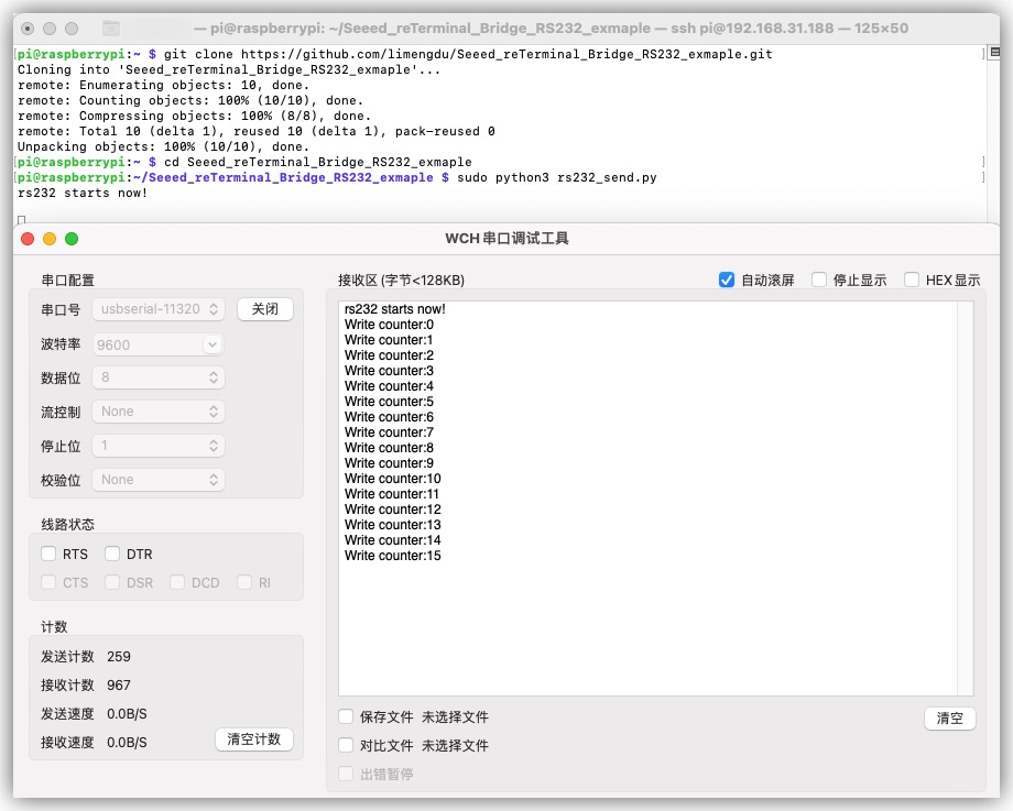
Here is the rs232_send.py code for reference.
#!/usr/bin/env python
import time
import serial

ser = serial.Serial(
        port='/dev/ttyS0',              # Please modify here according to the serial port name displayed by reTerminal
        baudrate = 9600,
        parity=serial.PARITY_NONE,
        stopbits=serial.STOPBITS_ONE,
        bytesize=serial.EIGHTBITS,
        timeout=1
)
counter=0
try:
        print("rs232 starts now!\n")
        ser.write("rs232 starts now!\n".encode())
        while 1:
                ser.write(("Write counter:{}\n".format(counter)).encode())
                time.sleep(1)
                counter += 1
except KeyboardInterrupt:
    exit()
Another reTerminal compiles and runs the code that receives the data.
sudo python3 rs232_receive.py
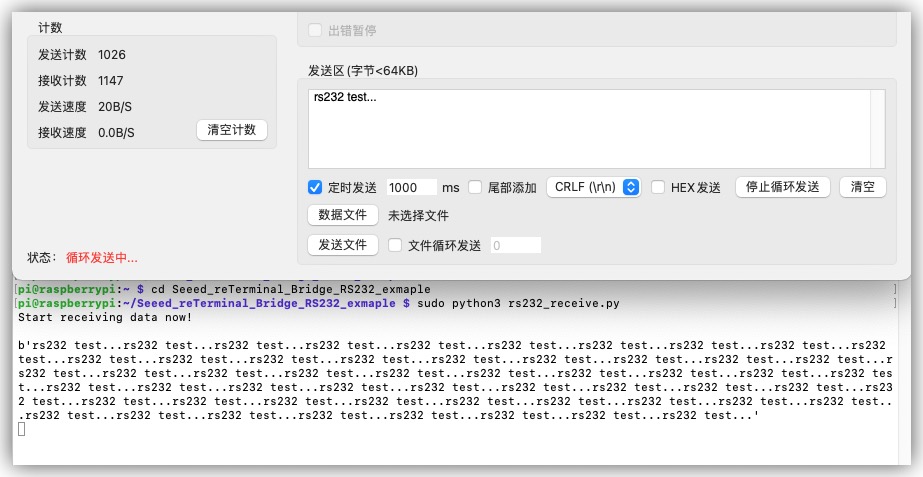
Here is the rs232_receive.py code for reference.
#!/usr/bin/env python
import time
import serial

ser = serial.Serial(
        port='/dev/ttyS0',
        baudrate = 9600,
        parity=serial.PARITY_NONE,
        stopbits=serial.STOPBITS_ONE,
        bytesize=serial.EIGHTBITS,
        timeout=1
)
try:
    print("Start receiving data now!\n")
    while 1:
            x=ser.readline()
            if x != b'':
                print(x)
except KeyboardInterrupt:
        exit()
Ethernet
Materials Required
- reTerminal x1
- reTerminal E10-1 x1
This example introduces how to test the ethernet connection on reTerminal E10-1.
Step 1. Download the iperf3 for reTerminal and computer.
git clone https://github.com/esnet/iperf.git
Step 2. Use the following codes to install the iperf3
cd iperf
sudo ./configure
sudo make
sudo make install
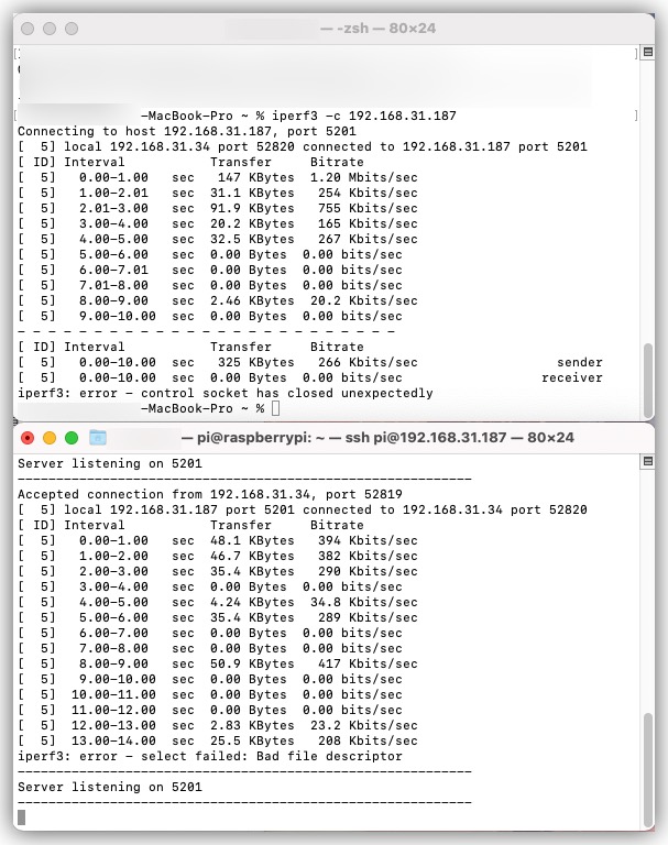
Step 3. Use reTerminal as server.
iperf3 -s
Use a computer to test the network speed connected to reTerminal. At this time, please keep the computer and reTerminal in the same local area network.
iperf3 -c 192.168.xxx.xxx
The address "192.168.xxx.xxx" above is the reTerminal address.
For example, in my setup the ip address of reTerminal is 192.168.31.187:
iperf3 -c 192.168.31.187
If you need to complete more network testing functions, you can refer to the use of query parameters on the iperf project website.
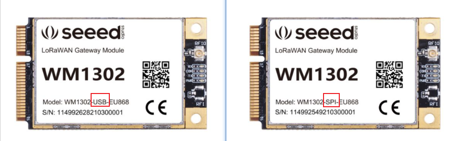
WM1302 (USB/SPI) LoRaWAN Gateway
Materials Required
The difference between USB and SPI module is shown below:
This example introduces how to use WM1302 LoRaWAN Gateway on reTerminal E10-1.
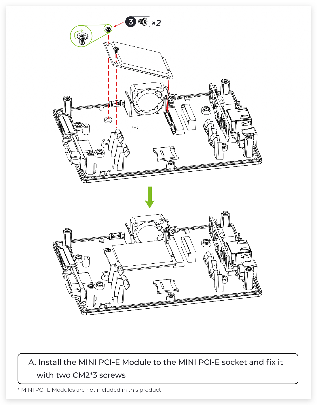
Step 1. Install the WM1302 module on the reTerminal E10-1, and then fix it with screws.

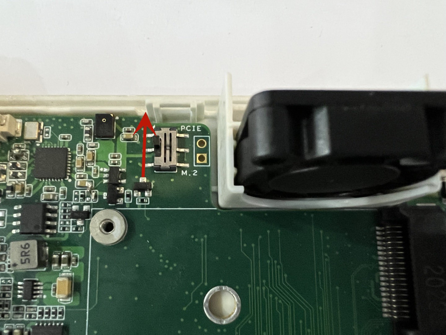
Then turn the button next to the fan to PCIE.
Step 2. type sudo raspi-config in command line to open Rasberry Pi Software Configuration Tool:
- Select Interface Options
- Select SPI, then select Yes to enable it
- Select I2C, then select Yes to enable it
- Select Serial Port, then select No for "Would you like a login shell..." and select Yes for "Would you like the serial port hardware..."
After this, please reboot Raspberry Pi to make sure these settings work.
Step 3. Download the WM1302 code to reTerminal and compile it.
git clone https://github.com/Lora-net/sx1302_hal
cd sx1302_hal
sudo make
Step 4. Configure the reset script. First download the file to sx1302_hal/packet_forwarder use the command
cd sx1302_hal/packet_forwarder
wget https://files.seeedstudio.com/wiki/reTerminal_Bridge/reset_lgw.sh
Then run the following code test according to your WM1302 version.
USB version
$ cd packet_forwarder
$ sudo nano reset_lgw.sh
$ ./lora_pkt_fwd -c global_conf.json.sx1250.EU868.USB
SPI version
$ cd packet_forwarder
$ sudo nano reset_lgw.sh
$ ./lora_pkt_fwd -c global_conf.json.sx1250.EU868
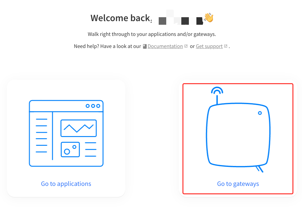
Step 5. Sign up at TTN website and log into your account. If you don't have one please registe. Then enter the Gateway interface and click "Get Starting"

Select your region.

Chose "Go to gateways"
Click Add gateway to add the device:
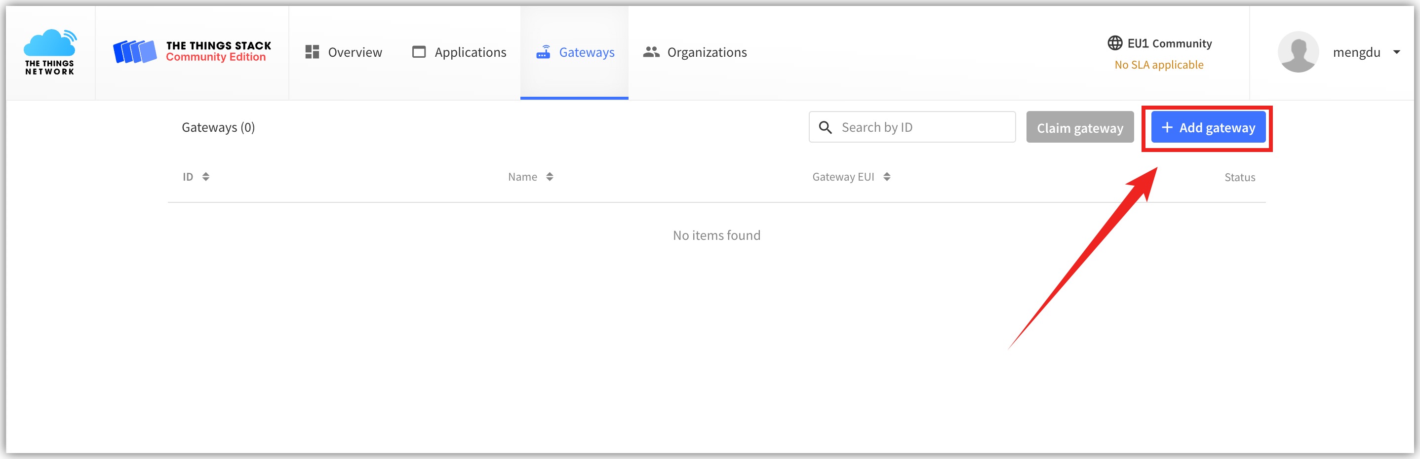
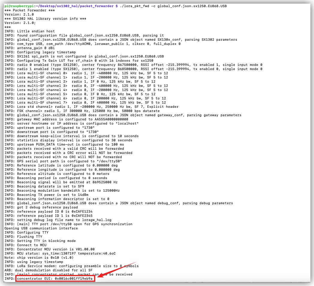
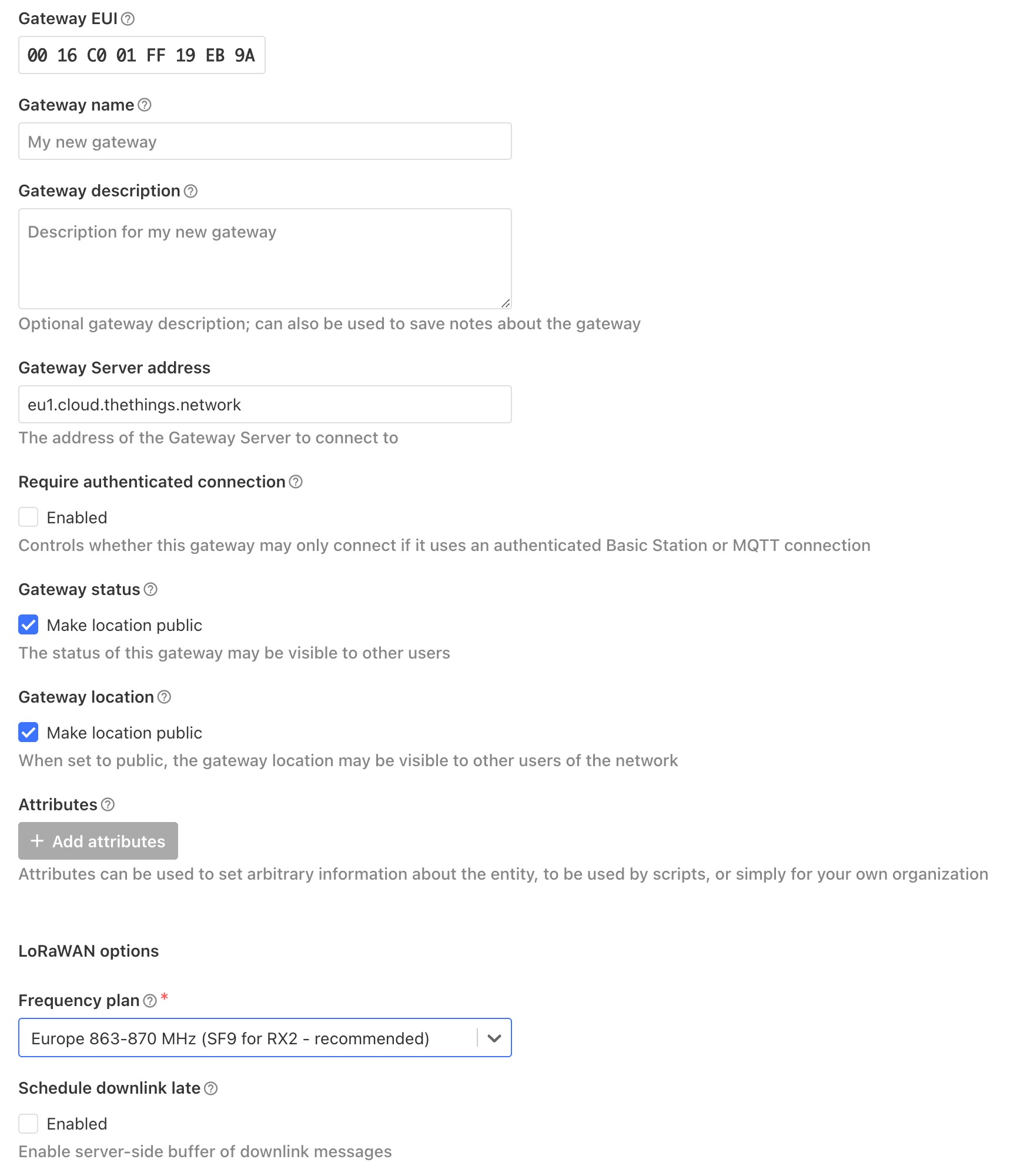
Among them, the value of Gateway EUI will be displayed in the log when the test is run in step 4. The Frequency plan in Lora options (take the European version as an example) select Europe 863-870 MHz (SF9 for RX2 - recommended). Then click on Create gateway.
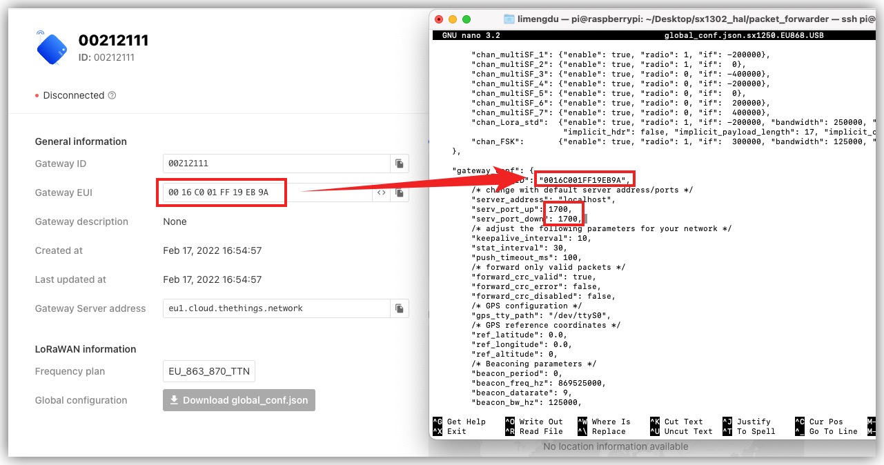
Step 6. (Take the European version as an example) If it is SPI version, edit global_conf.json.sx1250.EU868 in the sx1302_hal/packet_forwarder.
If it is USB version, edit global_conf.json.sx1250.EU868.USB in the sx1302_hal/packet_forwarder.
Search for gateway_conf in the corresponding file.
-
Then change the gateway_ID behind to the Gateway EUI filled in the webpage.
-
server_address is modified to the Gateway Server address in the web page.
-
Both serv_port_up and serv_port_up are modified to 1700.
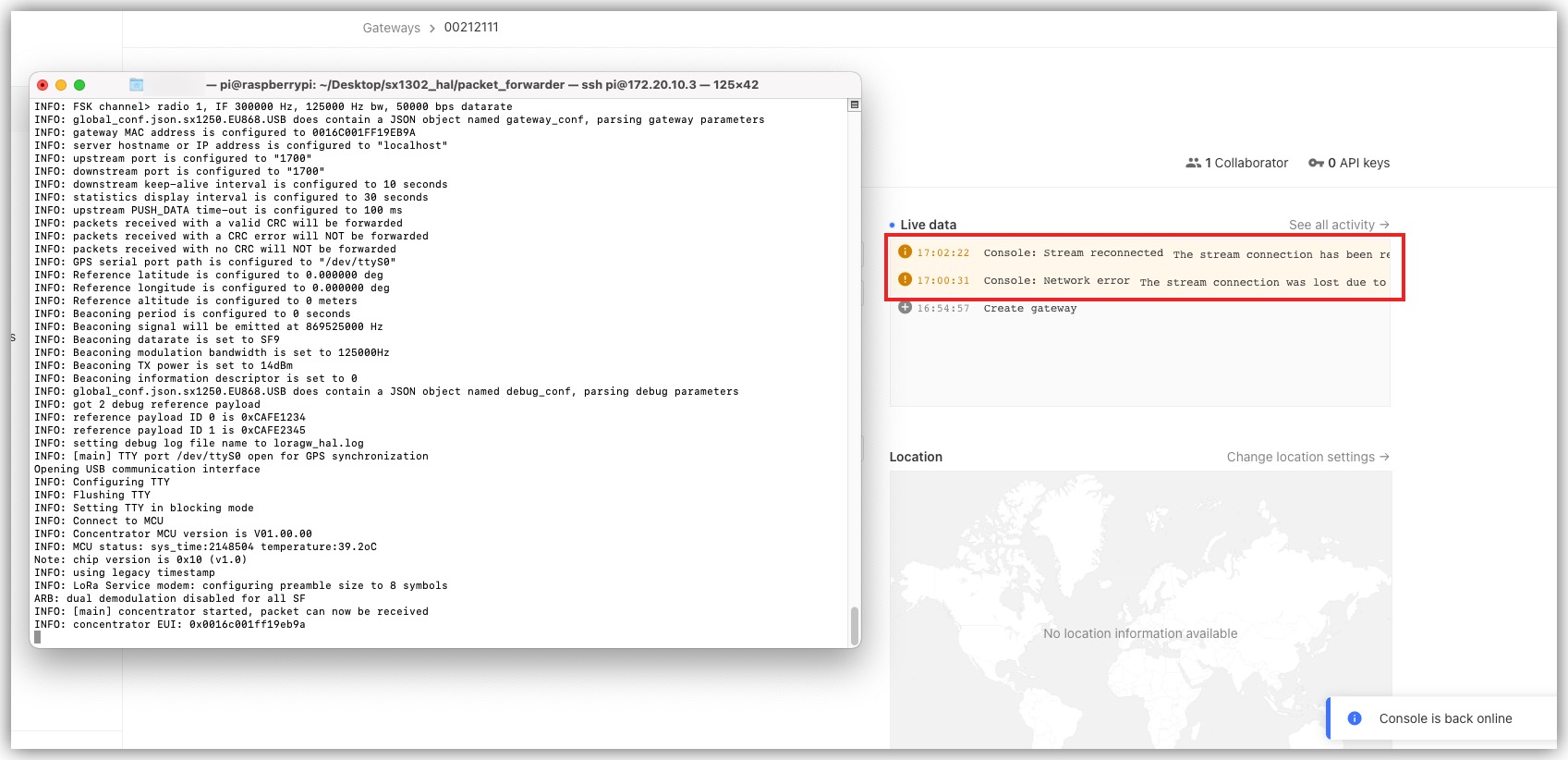
Step 7. Run the command in step 4 again, and you can see the connection information of the device on the web page later.
USB version
$ ./lora_pkt_fwd -c global_conf.json.sx1250.EU868.USB
SPI version
$ ./lora_pkt_fwd -c global_conf.json.sx1250.EU868
The above tutorial is based on the European version of WM1302. If you are using the US version of the WM1302, the steps are generally the same, but the files to modify and run in the tutorial will be different. The file name refers to the version you purchased and the following pages.
Hard Drive Expansion
Materials Required
- reTerminal x1
- reTerminal E10-1 x1
- M.2 B key Connector x1
This example introduces how to install and check hard disk operation on reTerminal E10-1.
Step 1. Open the back cover of the reTerminal E10-1, insert the M.2 SSD into the Mini-PCIe Connector and fix it with screws. Close the back cover, connect the reTerminal and power up.
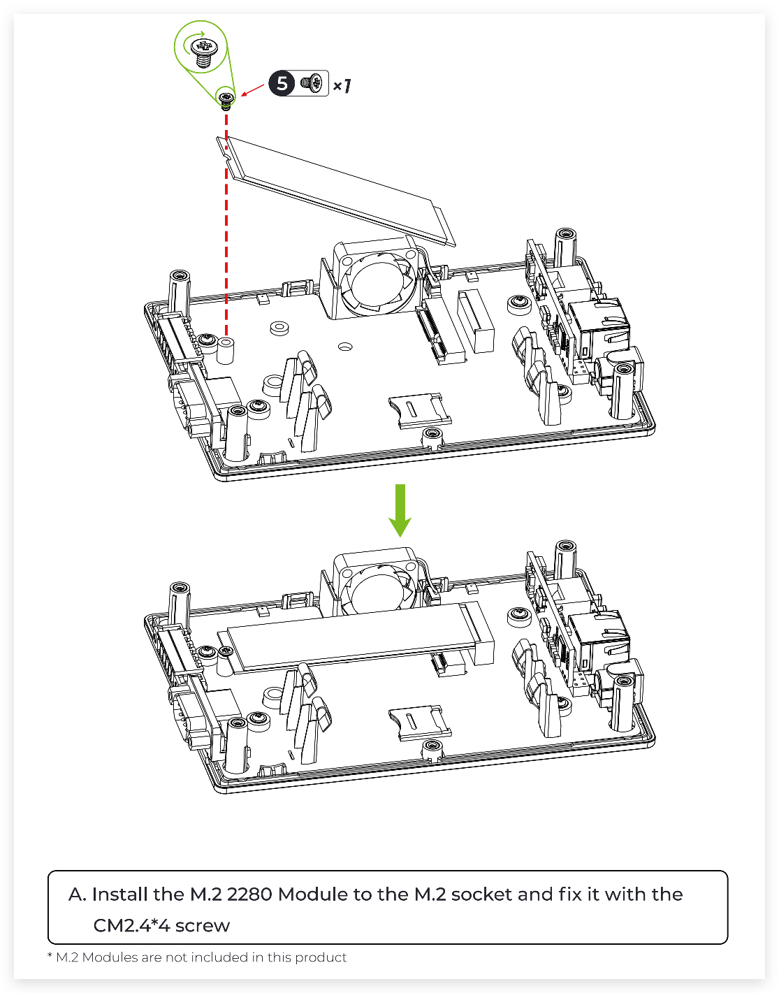
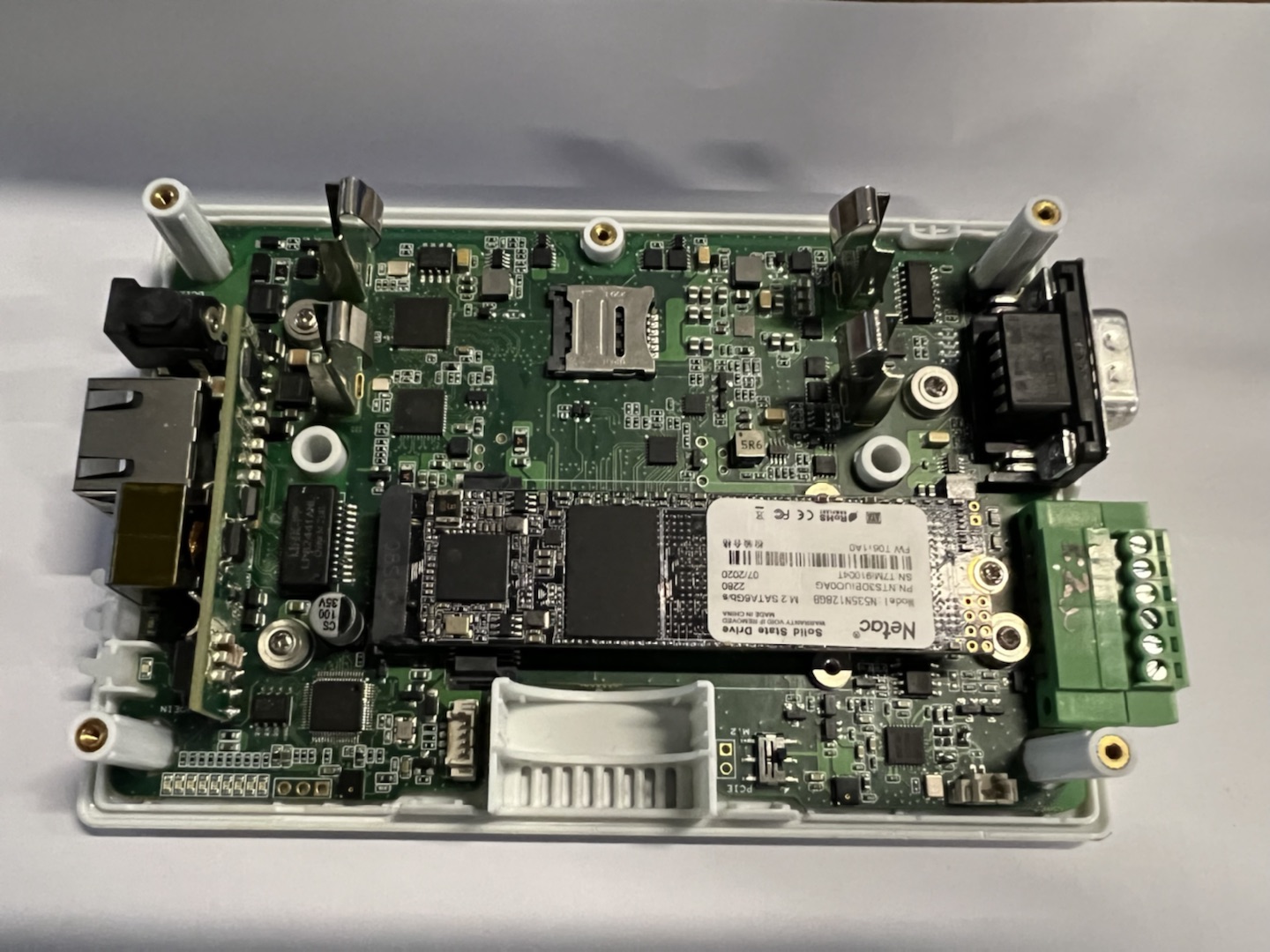
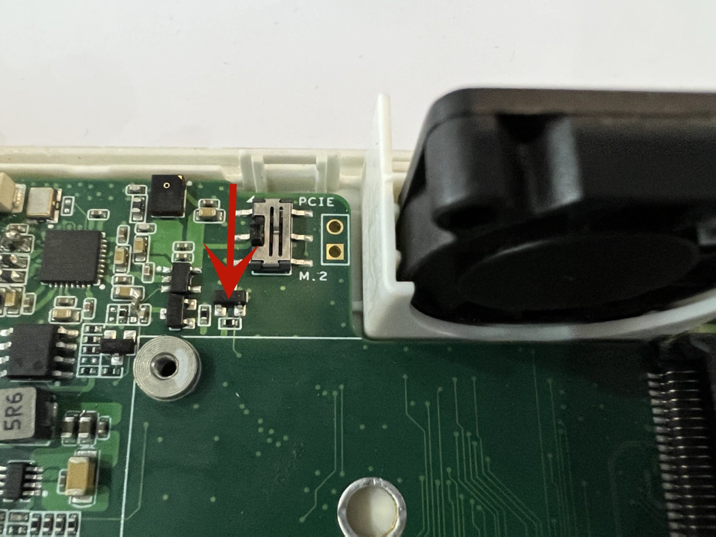
Then turn the button next to the fan to M.2.
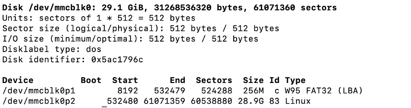
Step 2. Enter the command to see if the SSD storage device is detected.
sudo fdisk -l
Step 3. We can also use the dd command to test the read and write speed of the hard drive.
Read
$ sudo dd if=/dev/sda3 of=/dev/null bs=512k count=500
Write
$ sudo dd if=/dev/zero of=/dev/sda3 bs=512k count=500
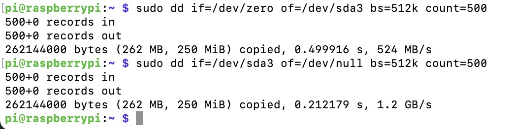
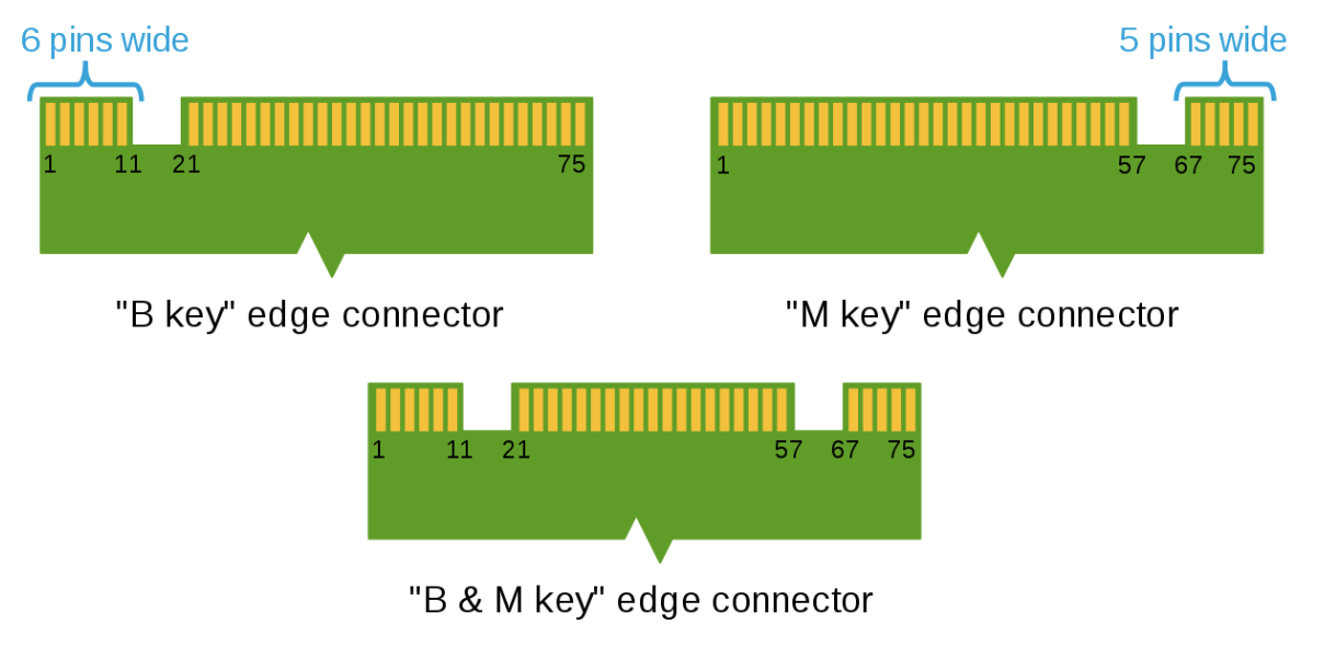
Make sure you are using M.2 B key.
Format Harddrive
The following step will wipe all your data from the SSD you have connected to the reTerminal E10-1, also if you have selected the wrong drive media you, so please make sure you have followed the steps below carefully and make sure you understand purpose each of the steps.
- Software Tools used:
lsblk,fdisk,mkfs,mount,umount
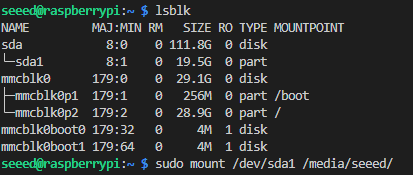
Step 1. Find your SSD device Name once you have connected your SSD in the reTerminal E10-1 and attached to the reTerminal, open terminal once the system has powered on, then type following command:
lsblk
you should see something similar:
Step 2. Using fdisk to partition your SSD
You will lose the data on the SSD that you have attached to the reTerminal E10-1, after following this step.
Followed by the steps above, type in following command in terminal, note the /dev/sdX where the X is the SSD device Name that you have choosen to get formated, make sure there are no other USB drives attached to reTerminal, unless you are confident with the correct device name.
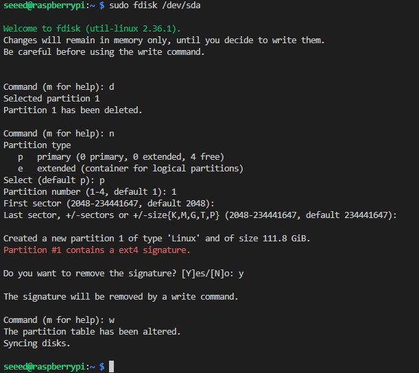
sudo fdisk /dev/sdX
For example, in my case:
sudo fdisk /dev/sda
you should see something similiar as shown below:
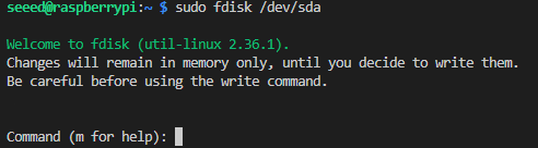
At the fdisk promte:
Welcome to fdisk (util-linux 2.36.1).
Changes will remain in memory only, until you decide to write them.
Be careful before using the write command.


Command (m for help):
First type d to delete the partitions on the SSD device.
Then followed by type n for create new partition on the SSD device.
After that you shuold see following message:
Partition type
   p   primary (0 primary, 0 extended, 4 free)
   e   extended (container for logical partitions)
Type p for create a primary partition, then followed by 1.
Then for the First sector, you can press ENTER for default of using the beginning sector of the drive, or you could specify where to start the partion 1 on your SSD at specific sector location. In my case I just pressed Ennter for default value.
Then followed by select the last sector for partion 1, if you want utilising the whole drive space for partition 1 just press ENTER, or your can type in the specific sector location for the end of partion 1 this also means the storage size of the partition 1 you are creating.
Then press Y for remove the signature.
Then followed by w to write the changes and then quit the fdisk promte.
Here is an example of the process:
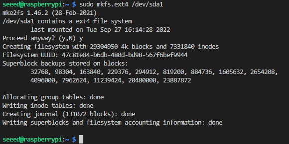
Step 3. Format your SSD partition to ext4 format Now you should create a partition/s for your SSD, you need to format the partition/s to the ext4 format in order to mount and use it. To do so by using the mkfs.ext4:
sudo mkfs.ext4 /dev/sdXX
similarly where the sdXX is the device name of your SSD, in my case i use /dev/sda1 like:
sudo mkfs.ext4 /dev/sda1
and at the Proceed anyway? (y,N) type y and ENTER, then wait couple secound until the process finished.
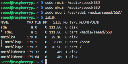
Step 4. Mount the partition Now you can mount the SSD to use as external disk for extra storage.
sudo mkdir /media/"YOUR USER NAME"/"THE NAME YOU WANT TO MOUNT THE DRIVE"

sudo mount /dev/sdXX /media/"YOUR USER NAME"/"THE NAME YOU WANT TO MOUNT THE DRIVE"
where "YOUR USER NAME" is the user name of your reTerminal system and "THE NAME YOU WANT TO MOUNT THE DRIVE" is the name you create to mount your drive, the /dev/sdXX is the device name of the SSD partition you want mount.
for example in my case:
sudo mkdir /media/seeed/SSD

sudo mount /dev/sda1 /media/seeed/SSD/
To check if the SSD successfully mounted by:
lsblk
you should see similar output as my, where the /dev/sda1 is mounted to /media/seeed/SSD:
EC25-EUX 4G Module
Materials Required
- reTerminal x1
- reTerminal E10-1 x1
- EC25-EUX 4G Module x1
- SIM Card x1
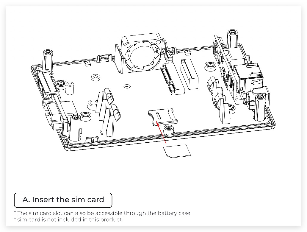
Step 1. Open the back cover of the reTerminal E10-1, then install the EC25-EUX and SIM card onto the reTerminal E10-1.
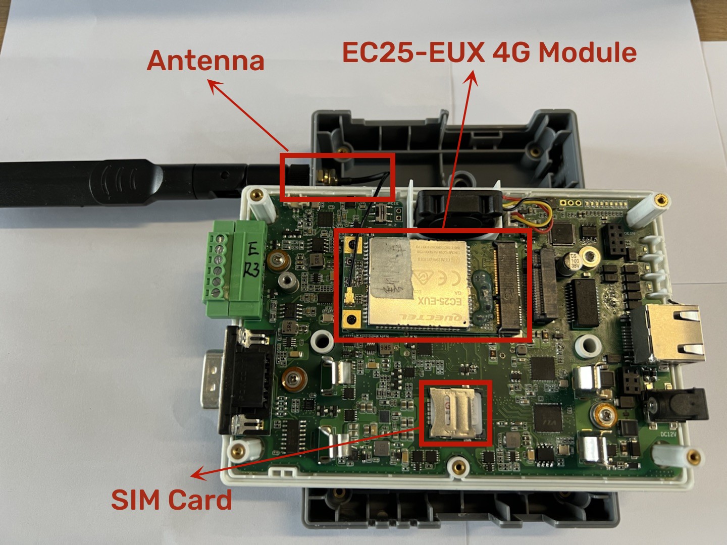
Then turn the button next to the fan to PCIE.
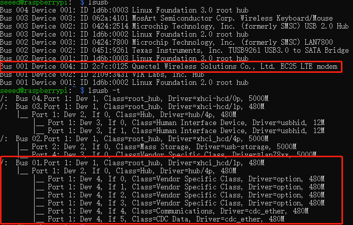
Step 2. Check if EC25-EUX gets detectd by using lsusb
lsusb
lsusb -t
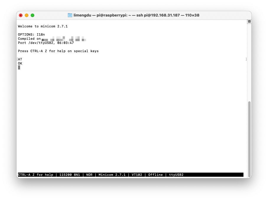
Step 3. Install the serial communication tool minicom.
sudo apt install minicom
Step 4. Connect EC25-EUX 4G module through minicom.
sudo minicom -D /dev/ttyUSB2 -b 1152008n1
once the serial connection opened, Type in AT and press 'Enter', and you should see OK.
Step 5. Enable 4G module to connect to 4G network
Please put in the 4G enabled sim-card in the sim card slot at Li-Po battery holder, where the sim card slot supports micro sim card, so if you have nano sim card you need to find a micro sim card adaptor to convert to micro sim card.
AT the same minicom serial window please type:
AT+QCFG="usbnet"
It will return something like +QCFG: "usbnet",0, but we need that to be set to 1 (ECM mode), so enter the following command:
AT+QCFG="usbnet",1
Then enter the following command to force the modem to reboot:
AT+CFUN=1,1
Then you could reboot or wait for a while for the moudel to get internet from your sim card carrier.
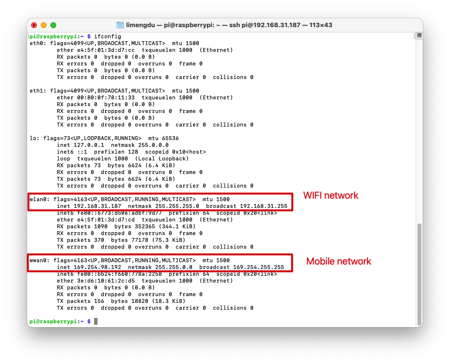
You can also use the command ifconfig to query the networking status of reTerminal.
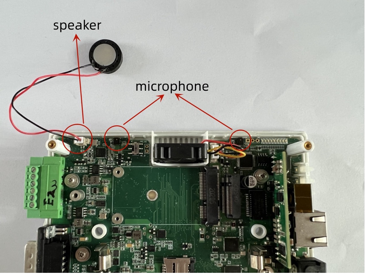
Audio
In order to meet the multimedia needs of different users, a speaker module and two microphone modules are installed inside the reTermnal E10-1 to achieve the needs of playing sound and recording.
Materials Required
- reTerminal x1
- reTerminal E10-1 x1
Step 1. Download and install the driver.
git clone https://github.com/Seeed-Projects/seeed-voicecard.git
cd seeed-voicecard
sudo ./install.sh
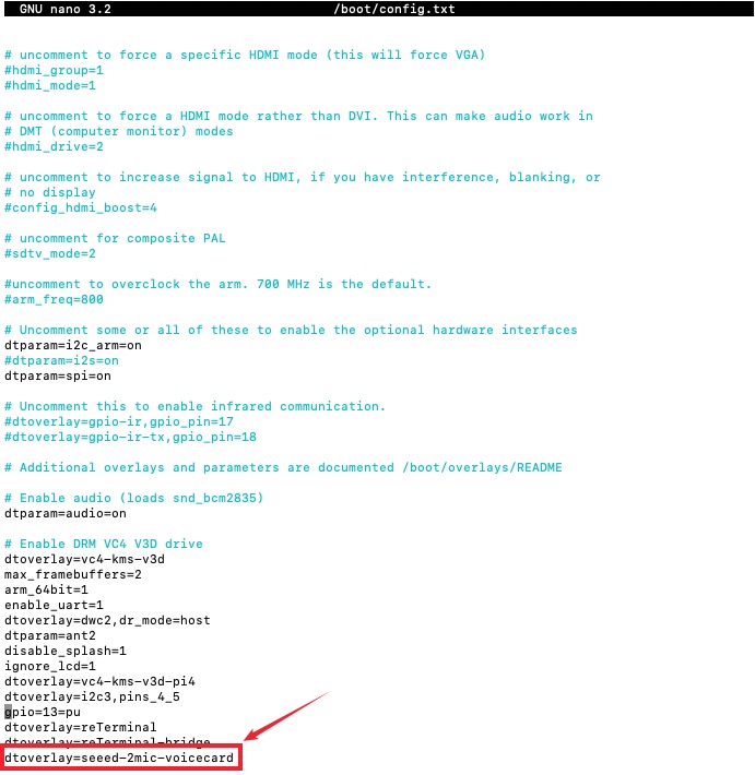
Step 2. Add configuration items. Add dtoverlay=seeed-2mic-voicecard to the /boot/config.txt. Then restart the device.
sudo sed -i '$s/$/\ndtoverlay=seeed-2mic-voicecard/' /boot/config.txt
to check if you have modified /boot/config.txt you can use nano text editor to open the file and scroll the last line to check:
nano /boot/config.txt
Once its added to the /boot/config.txt you can reboot now:
sudo reboot
After waiting for the restart, use the command arecord -l to view the recording device.
arecord -L
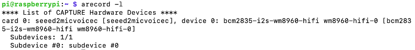
As shown in the figure above, card 0 device 0 is the device we need to use to record.
Step 3. According to the above information, use the command to perform the operation of recording and saving.
arecord -Dhw:0,0 -d 10 -f cd -r 44100 -c 2 -t wav test.wav
Parameter Parsing
- -D specifies the recording device, 0,0 means card 0 device 0, which is bcm2835-i2s-wm8960-hifi wm8960-hifi-0.
- -d specifies the duration of the recording, in seconds.
- -f specifies the recording format, only supports cd, cdr, dat.
- -r specifies the sampling rate in Hz.
- -c specifies the number of channels.
- -t specifies the generated file format.
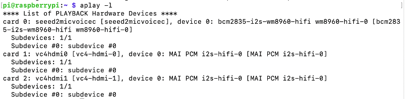
Step 4. Check the playback device.
aplay -l
Step 5. Adjust the appropriate volume to play the sound.
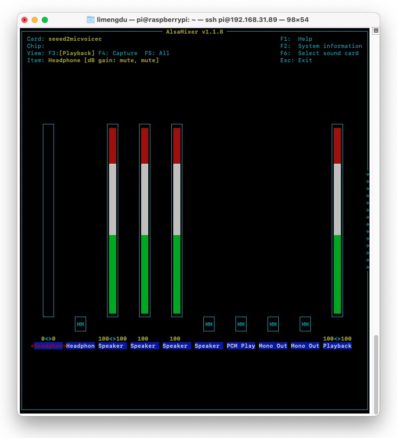
sudo alsamixer
sudo aplay -Dhw:0 test.wav

FAQ
- What type of 18650 batteries are compatible?
Answer: Panasonic NCR18650B 3.6V 3400mAh is recommended.
- Do the batteries need to have their own overcurrent/undervoltage/overvoltage protection?
Answer: No, because reTerminal E10-1 has battery protection circuit
- What model of CAN and RS485 controller does it use?
Answer:
- 485controller:TP485E
- CAN controller:MCP2518FDT-E/QBB
- Installed E10 yesterday, is the battery information (charge level) correct? shows it as red (0%) even if I just took them out of the charger.
Kernel: 5.10.103-v8+ aarch64 bits: 64 Console: tty 0 Distro: Debian GNU/Linux 10
Power display feature: not yet developed, but your voice got and we will schedule the development of this feature
- Is the reterminal extension provide another (separate) ethernet port --> so we have two ethernet port ?
These two ports can be used simultaneously without affecting each other.
- Is the RS232 and RS485 are independant/separated (sometimes, in some hardware, you can use juste one ...)
You can only use either RS232 or RS485 at one time.
Tech Support & Product Discussion
Thank you for choosing our products! We are here to provide you with different support to ensure that your experience with our products is as smooth as possible. We offer several communication channels to cater to different preferences and needs.