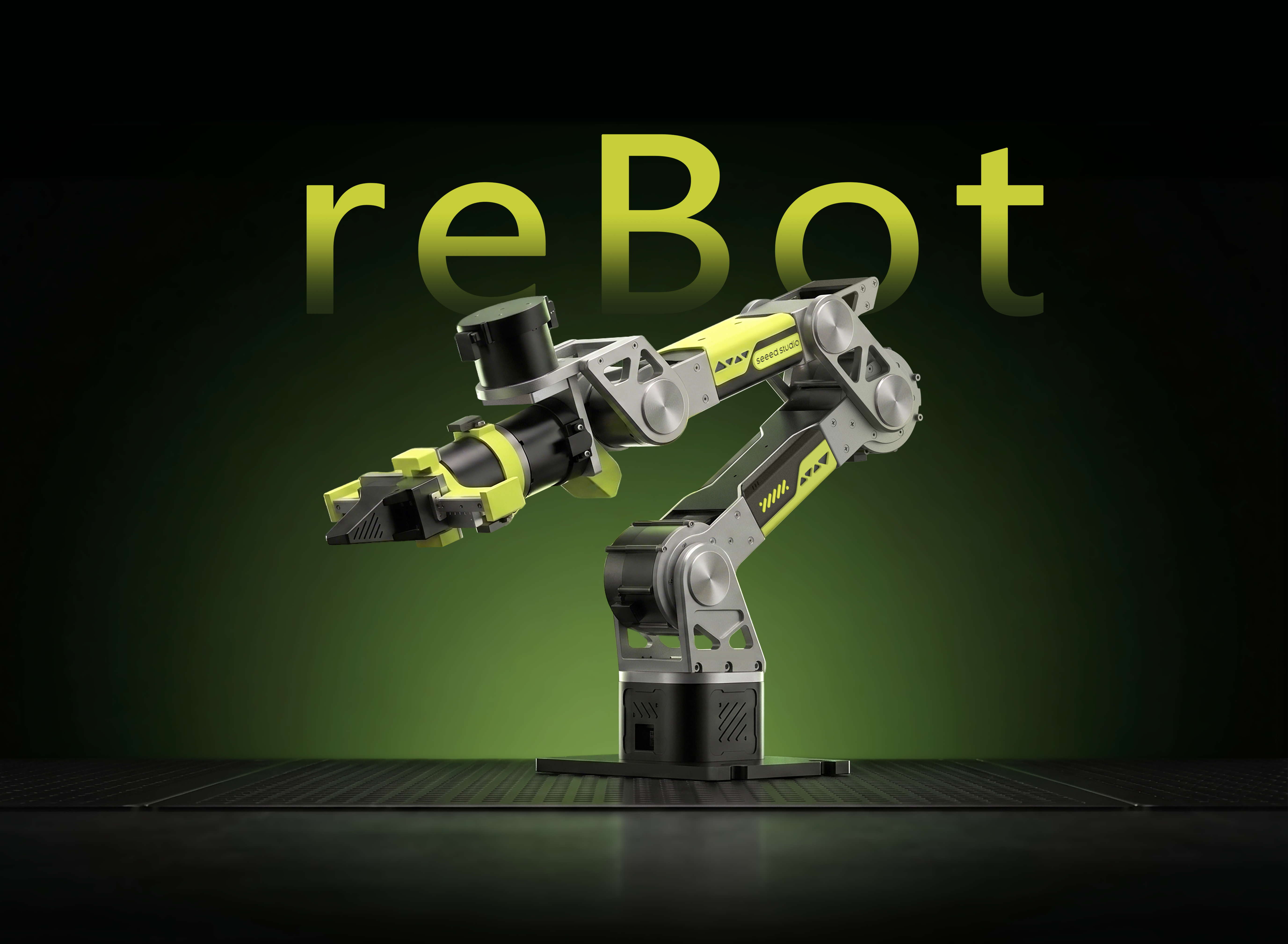
Getting Started with Pinocchio and MeshCat for reBot Arm B601-RS
![]()
![]()
![]()
![]()
6-DOF Robotic Arm · Multi-Motor Support · Kinematics Solver · Trajectory Planning · Fully Open Source
Pinocchio is an open-source library for robot dynamics analysis and optimization. It provides efficient forward/inverse kinematics, dynamics computation, and trajectory planning. MeshCat is a web-based 3D visualization tool that can display robot states and motion trajectories in real time.
This project combines Pinocchio's powerful computation capabilities with MeshCat's intuitive visualization, providing a complete set of kinematics analysis and debugging tools for reBot Arm B601-RS.
Project Features
-
Complete Kinematics Analysis Supports forward kinematics (FK) and inverse kinematics (IK) calculations, enabling real-time solving of the robotic arm's end-effector pose.
-
Real-time 3D Visualization Displays the robotic arm's state and motion trajectories in the browser through MeshCat in real time, without additional software.
-
Trajectory Planning and Tracking Implements SE(3) geodesic trajectory planning, supporting CLIK (Closed-Loop Inverse Kinematics) tracking control.
-
Gravity Compensation Control Calculates joint gravity torques based on the Pinocchio dynamics model, achieving a "floating" effect for the robotic arm. Supports both basic and end-effector velocity lock versions.
-
Multi-Mode Motor Control Supports MIT, POS_VEL, and VEL control modes, compatible with both Damiao and Robostride motor protocols.
-
Open Source & Extensible All code is open source, allowing users to customize control algorithms and visualization effects according to their needs.
Specifications
The hardware for this tutorial is provided by Seeed Studio
| Parameter | Specification |
|---|---|
| Robot Arm Model | reBot Arm B601-RS Assembled Kit with Gripper |
| Degrees of Freedom | 6+1 (with gripper) |
| Reach | 754.7 mm (with gripper) / 587.5 mm (without gripper) |
| Load Capacity | Rated load 2.5 kg / Max load 5 kg |
| Joint Range of Motion | J1: ±150° / J2: 220° ~ 0° / J3: 220° ~ 0° / J4: ±90° / J5: ±90° / J6: ±180° / Gripper: 345° ~ 0° |
| Repeatability | 0.1 mm |
| Self Weight | 6.7 kg |
| Servo Motors | RobStride 06 × 3 / RobStride 00 × 4 |
| Communication | CAN Bus @ 1 Mbps |
| Operating Voltage | DC 48V |
| Power Supply | DC 48V 15A |
| Operating Temperature | -20°C ~ 50°C |
| Control Method | PC |
Supported Software Platforms
| Platform | Support Status |
|---|---|
| ROS1 | ✅ |
| MoveIt1 | ✅ |
| ROS2 | ✅ |
| MoveIt2 | ✅ |
| Python | ✅ |
| LeRobot | ✅ |
| Isaac Sim | ✅ |
| Pinocchio | ✅ |
Joint Motor Parameters
| Parameter | RobStride 00 | RobStride 06 |
|---|---|---|
| Rated Voltage | 48V | 48V |
| Rated Current | 4.7 Apk ± 10% | 14.3 Apk ± 10% |
| Peak Current | 15.5 Apk ± 10% | 57 Apk ± 10% |
| Rated Torque | 5 N.m | 11 N.m |
| Peak Torque | 14 N.m | 36 N.m |
| Rated Speed | 100 rpm ± 10% | 100 rpm ± 10% |
| No-Load Max Speed | 315 rpm ± 10% | 480 rpm ± 10% |
| Reduction Ratio | 10 : 1 | 9 : 1 |
| Pole Pairs | 28 | — |
| Motor Inductance | 750 ± 20 μH | 0.165 mH ± 10% |
| Line Resistance | 1.5 ± 10% Ω | 0.23 ± 10% Ω |
| Outer Diameter | 57 mm | 82 mm |
| Height | 51 ± 1 mm | 49 ± 0.5 mm |
| Motor Weight | 310 g ± 3 g | 621 g |
| Encoder Resolution | 14 bit (single-turn absolute) | |
| Encoder Count | 2 | |
| Encoder Type | Magnetic encoder (single-turn) | |
| Control Interface | CAN @ 1 Mbps | |
| Debug Interface | UART @ 921600 bps | |
| Control Modes | MIT Mode / Speed Mode / Position Mode / Torque Mode | |
| Protection | Over-temperature protection: motor thermistor temperature exceeds 145°C Under-voltage protection: motor voltage below protection voltage 12V |
Bill of Materials (BOM)
| Component | Quantity | Included |
|---|---|---|
| reBot Arm B601-RS Robotic Arm | 1 | ✅ |
| CANABLE | 1 | ✅ |
| Power Adapter (DC 48V 15A) | 1 | ✅ |
| USB-C Cable | 1 | ✅ |
| Gripper | 1 | ✅ |
Environment Requirements
| Item | Requirement |
|---|---|
| Python | 3.10+ |
| Operating System | Ubuntu 22.04+ |
| Communication Interface | CAN interface (can0) |
| Power Supply | DC 48V 15A |
While the robotic arm is running examples, it must operate within 70% of the arm's reach workspace. Staying outside the workspace for an extended period will cause the second joint motor to enter stall protection, resulting in the arm dropping.
Installation Steps
Step 1. Install uv (if not installed)
curl -LsSf https://astral.sh/uv/install.sh | sh
Step 2. Sync Environment (Install All Dependencies)
git clone https://github.com/vectorBH6/reBotArm_control_py.git
cd reBotArm_control_py
uv sync
uv sync will automatically create a virtual environment (if it doesn't exist) and install all dependencies based on pyproject.toml and uv.lock.
Step 3. Modify Configuration File for RS Version
This Wiki is for reBot Arm B601-RS. Before running any examples, please switch the hardware configuration in config/rebotarm.yaml from the DM version to the RS version:
# Before modification
hardware_yaml: "rebotarm_dm.yaml"

# After modification
hardware_yaml: "rebotarm_rs.yaml"
If this configuration is not modified, the program will communicate using the Damiao motor protocol, causing the RS motors to fail to be recognized or run properly.
Debugging Tools
Before running real-machine control examples and debugging motors, you need to set up the CAN channel (for PCAN-USB, you need to configure this again after re-plugging):
# PCAN-USB should usually appear directly as can0 or can1
sudo modprobe peak_usb
ip -br link

# If can0 appears, set the bitrate
sudo ip link set can0 down 2>/dev/null
sudo ip link set can0 type can bitrate 1000000
sudo ip link set can0 up    # Bring up can0
Single Motor Console — Robostride RS06 (0x01rs06_test.py)
Directly use the motorbridge SDK for Robostride RS06 single motor testing. RS06 motors communicate via CAN bus.
Run Command:
uv run python example/0x01rs06_test.py
Interactive Commands:
| Command | Description |
|---|---|
enable / disable | Enable/Disable |
set_zero | Set software zero position |
state | View current state |
ping | Ping motor to get response |
clear_error | Clear motor errors |
mode <mit/posvel/vel> | Switch control mode |
mit <pos> [vel] [kp] [kd] | MIT mode command |
posvel <pos> [vlim] | POS_VEL mode command |
vel <velocity> | Pure velocity mode command |
read_param <id> [type] | Read motor parameters |
write_param <id> <value> [type] | Write motor parameters |
loop | Enter loop control mode |
q / quit | Quit |
Note: Robostride motors use the CAN interface (default can0), with host/feedback ID defaulting to 0xFD. During motor testing, the motor needs to be disabled first and then re-enabled to allow normal reading and control.
Zero Calibration and Angle Monitoring (2_zero_and_read.py)
Automatically set all joint zero positions and display joint angles in real time.
Run Command:
uv run python example/2_zero_and_read.py

# Example output
-0.12  +0.23  -6.42  +41.74  -0.45  -0.01  -0.01
Basic Control Tests
MIT Mode Full Joint Control (3_mit_control.py)
All joints use MIT mode uniformly, sending control commands synchronously every cycle.
Input: All joint angles (degrees), space-separated. If gripper is configured, an additional gripper angle is required.
Run Command:
uv run python example/3_mit_control.py
> 30 0 0 0 0 0 # Control motor 1 to rotate 30 degrees
> state
  pos (deg): ['+29.99', '+0.00', '-45.00', '+0.00', '+0.00', '+0.00']
> q # Exit system
Note that in MIT control mode, the robotic arm moves very fast. Ensure that people and other devices are away from the arm's working radius.
POS_VEL Mode Full Joint Control (4_pos_vel_control.py)
Input all joint target angles to complete motor control in POS_VEL (Position-Velocity) hybrid control mode, achieving smoother and more controllable motion when reaching target angles, reducing vibration.
Run Command:
uv run python example/4_pos_vel_control.py
> 30 0 0 0 0 0 # Control motor 1 to rotate 30 degrees
> state
  pos (deg): ['+29.99', '+0.00', '-45.00', '+0.00', '+0.00', '+0.00']
> q # Exit system
Kinematics Tests
Forward Kinematics Test (5_fk_test.py)
Calculate the end-effector pose based on joint angles.
Input: 6 joint angles (degrees)
Output:
- End-effector position (X, Y, Z) — unit: meters
- Rotation matrix (3×3)
- Euler angles (roll/pitch/yaw) — unit: degrees
Example:
uv run python example/5_fk_test.py
> 0 0 0 0 0 0
> 45 -30 15 -60 90 180
Inverse Kinematics Test (6_ik_test.py)
Solve joint angles based on the desired end-effector pose.
Input Format:
- Position only:
<x> <y> <z>(meters) - Position + Orientation:
<x> <y> <z> <roll> <pitch> <yaw>(degrees)
Example:
uv run python example/6_ik_test.py
> 0.25 0.0 0.15              # Position only
> 0.25 0.0 0.15 0 0 0        # Position + orientation
Inverse Kinematics Control in MIT Mode (7_arm_ik_control.py)
Use inverse kinematics (IK) in MIT mode to specify the 3D coordinates (X, Y, Z) and orientation (Euler angles) where the robotic arm end-effector should move.
Input Format:
- Position only:
<x> <y> <z>(meters) - Position + Orientation:
<x> <y> <z> <roll> <pitch> <yaw>(degrees) - Input
state: View current actual radian values of each joint. - Input
end_state: View current end-effector actual coordinates (m) and Euler angles (rad) in space.
Run Command:
uv run python example/7_arm_ik_control.py

#Usage A
> 0.3 0.0 0.4 # Position only (orientation defaults to 0), move the arm end-effector to 0.3 meters forward and 0.4 meters above.

#Usage B
> 0.3 0.0 0.4 0.0 0.0 0.5 # Control both position and orientation: move to the specified position while rotating the wrist yaw angle by 0.5 radians.

> ctrl + c # Exit system
Note that in this example code, the robotic arm moves very fast. Ensure that people and other devices are away from the arm's working radius.
Inverse Kinematics Control with Smooth Trajectory (8_arm_traj_control.py)
Use inverse kinematics (IK) in MIT mode to automatically plan a uniform or smooth acceleration/deceleration motion trajectory within the target time, avoiding severe joint vibration.
Input Format:
- Position only:
<x> <y> <z>(meters) - Position + Orientation:
<x> <y> <z> <roll> <pitch> <yaw>(degrees) - Position + Orientation + Time (default 2.0):
<x> <y> <z> <roll> <pitch> <yaw> <time>(degrees) - Input
state: View current actual radian values of each joint. - Input
end_state: View current end-effector actual coordinates (m) and Euler angles (rad) in space.
Run Command:
uv run python example/8_arm_traj_control.py

#Usage A
> 0.3 0.0 0.4 # Position only, orientation defaults to 0, default movement time is 2.0 seconds

#Usage B
> 0.3 0.0 0.4 0.0 0.0 0.5 # Control both position and orientation: move to the specified position while rotating the wrist yaw angle by 0.5 radians, default movement time is 2.0 seconds

#Usage C
> 0.3 0.0 0.4 0.0 0.0 0.0 5.0 # Move the arm to the specific position and specify 5.0 seconds to slowly move there. (Note: If entering time, the preceding orientation parameters 0 0 0 cannot be omitted)

> ctrl + c # Exit system
Gravity Compensation Control — Basic Version (9_gravity_compensation.py)
Use the Pinocchio dynamics model to compensate for joint gravity.
Control Law:
tau = g(q)          — Gravity feedforward
pos = current motor position   — Joint position follows current position
kp = 2,  kd = 1     — Unified stiffness/damping for all joints
Expected Behavior:
- The robotic arm can "float" at any pose
- Will not fall due to self-weight after release
- Can be manually moved to any position
Run Command:
uv run python example/9_gravity_compensation.py
Output:
- Display desired torque for each joint in real time (N·m)
- Press
Ctrl+Cto stop and disconnect
When stopping the script (Ctrl+C), the program will directly disable all motors, and the robotic arm will not automatically return to zero. Please hold the robotic arm by hand or move it to a safe/home pose before exiting to avoid sudden joint drops that may cause collisions or damage.
If some joints are under-compensated or over-compensated due to structural friction or assembly differences, you can apply additional scaling to the corresponding element of the tau_g array in the code:
tau_g[x] *= y  # x is the joint motor id, y is the compensation factor, usually starting from 1
# This compensation is generally only used for joints 2 and 3
For example, tau_g[2] *= 1.2 means increasing the gravity compensation torque of joint 2 by 20%. It is recommended to adjust item by item based on the actual floating effect to avoid making excessively large changes at once.
Gravity Compensation Control — End-Effector Velocity Lock Version (10_gravity_compensation_lock.py)
Based on the basic gravity compensation, adds end-effector velocity detection and joint angle locking mechanism.
Control Law:
tau = g(q) + integral_term    — Gravity feedforward + integral term
pos = q_target                 — Target joint angle (locked or updated)
kp = 8.0,  kd = 1.0           — Enhanced stiffness/damping
Lock Logic:
- When end linear velocity
||v_ee|| < 0.04 m/sand angular velocity||w_ee|| < 0.08 rad/s:- Target joint angle
q_targetremains locked - Robotic arm locks in current position
- Target joint angle
- When end velocity exceeds threshold:
q_targetupdates to current joint angle- Allows manual pushing to change position
Expected Behavior:
- Robotic arm locks in current position, requiring force to change target angle
- More stable than basic version, suitable for scenarios requiring pose maintenance
Run Command:
uv run python example/10_gravity_compensation_lock.py
Output:
- Display lock status in real time (LOCKED / UPDATE)
- End linear velocity, angular velocity
- Gravity compensation torque for each joint (N·m)
- Press
Ctrl+Cto stop and disconnect
When stopping the script (Ctrl+C), the program will directly disable all motors, and the robotic arm will not automatically return to zero. Please hold the robotic arm by hand or move it to a safe/home pose before exiting to avoid sudden joint drops that may cause collisions or damage.
If some joints are under-compensated or over-compensated due to structural friction or assembly differences, you can apply additional scaling to the corresponding element of the tau_g array in the code:
tau_g[x] *= y  # x is the joint motor id, y is the compensation factor, usually starting from 1
# This compensation is generally only used for joints 2 and 3
For example, tau_g[2] *= 1.2 means increasing the gravity compensation torque of joint 2 by 20%. It is recommended to adjust item by item based on the actual floating effect to avoid making excessively large changes at once.
Safety Test Configuration:
You can modify the ENABLED_JOINTS list at the top of the script to enable only specified joints for safety testing:
ENABLED_JOINTS = ["joint1"] # Enable only joint1
Simulation Environment
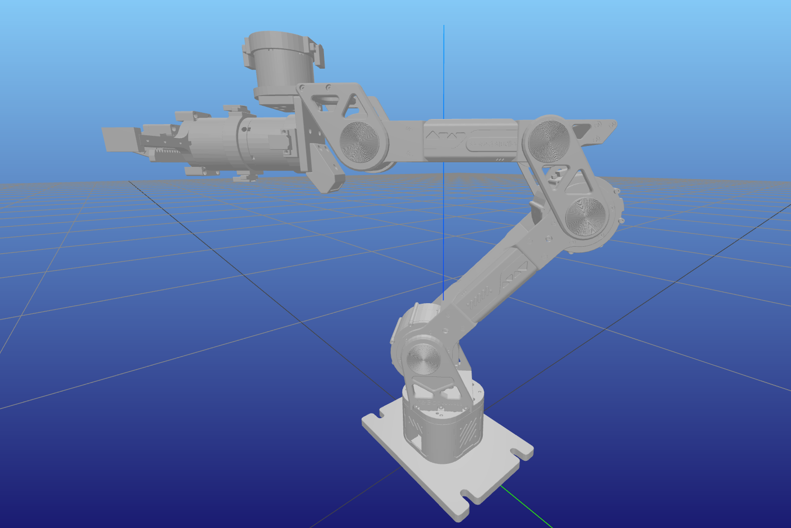
Forward Kinematics Simulation (sim/fk_sim.py)
Interactive forward kinematics simulation, visualizing the robotic arm's pose in MeshCat by inputting joint angles.
Run Command:
uv run python example/sim/fk_sim.py
Interactive Commands:
- Input 6 joint angles (degrees), space-separated
- Example:
0 0 0 0 0 0 - Example:
45 -30 15 -60 90 -180 q/quit/exit: Exit
Features:
- Display end-effector position and orientation in real time
- Support continuous input to test different poses
- Output formatted pose information
Inverse Kinematics Simulation (sim/ik_sim.py)
Interactive inverse kinematics simulation, automatically solving joint angles and visualizing for a target pose.
Run Command:
uv run python example/sim/ik_sim.py
Input Format:
- Position only:
x y z(meters) - Position + Orientation:
x y z roll pitch yaw(radians)
Example:
> 0.25 0.0 0.25              # Position only
> 0.25 0.0 0.25 0 0 0        # Position + orientation
Features:
- Automatically determine whether IK converges
- Display iteration count and error
- Update robot pose in real time
Trajectory Planning Simulation (sim/traj_sim.py)
SE(3) geodesic trajectory planning simulation, including CLIK tracking and MeshCat animation playback.
Run Command:
uv run python example/sim/traj_sim.py
Interactive Commands:
- Input:
x y z [roll pitch yaw](meters/radians) - Press Enter directly to use default configuration
q: Quit
Features:
- Plan from current position to target pose
- Use minimum jerk trajectory profile
- Display trajectory statistics in real time
- Playback full trajectory animation in MeshCat
- Display reference path (gray) and actual path (green)
Visualization Tool (sim/visualizer.py)
MeshCat visualizer wrapper, providing a unified robot display interface.
Main Functions:
- Load URDF model and display robot
- Draw 3D polyline paths (reference/actual)
- Display IK target pose (three-color axes + sphere)
- Support joint trajectory animation playback
Usage Example:
from example.sim.visualizer import Visualizer
viz = Visualizer()
viz.update(q)  # Update robot pose
viz.draw_path(points, "path_name", color)  # Draw path
FAQ
-
Encounter
Permission deniederror Make sure to runsudo chmod 666 /dev/ttyACM0(Damiao) orsudo chmod 666 /dev/can0(Robostride) to set device permissions. -
IK solving fails or results are abnormal Check whether the target pose is within the robotic arm's workspace and ensure joint limits are configured correctly.
-
Gravity compensation effect is poor This may be caused by structural errors and machining accuracy. The gravity compensation in this project relies on URDF and Pinocchio. You can try correcting the URDF to parameters you actually measured (you can ask AI for this step).
-
Robostride motors cannot read status Internal protocol configuration issues in motorbridge may prevent RS motors from querying status like DM motors. Please judge based on actual motion effects, or try using the
pingcommand to confirm normal motor communication. -
How to switch between Damiao and Robostride motor configurations Modify the
config/rebotarm_dm.yaml(Damiao) orconfig/rebotarm_rs.yaml(Robostride) configuration file and load the corresponding configuration in the code. -
If the robotic arm remains stationary beyond 70% of the arm's reach workspace for an extended period, the second joint motor will enter stall protection
Power cycle the robotic arm; the second joint motor stall protection error will clear automatically.
Contact
- Technical Support: Submit Issue
- Project Repository: GitHub
- Forum: Seeed Studio Forum