reBot Arm B601-DM Quick Start
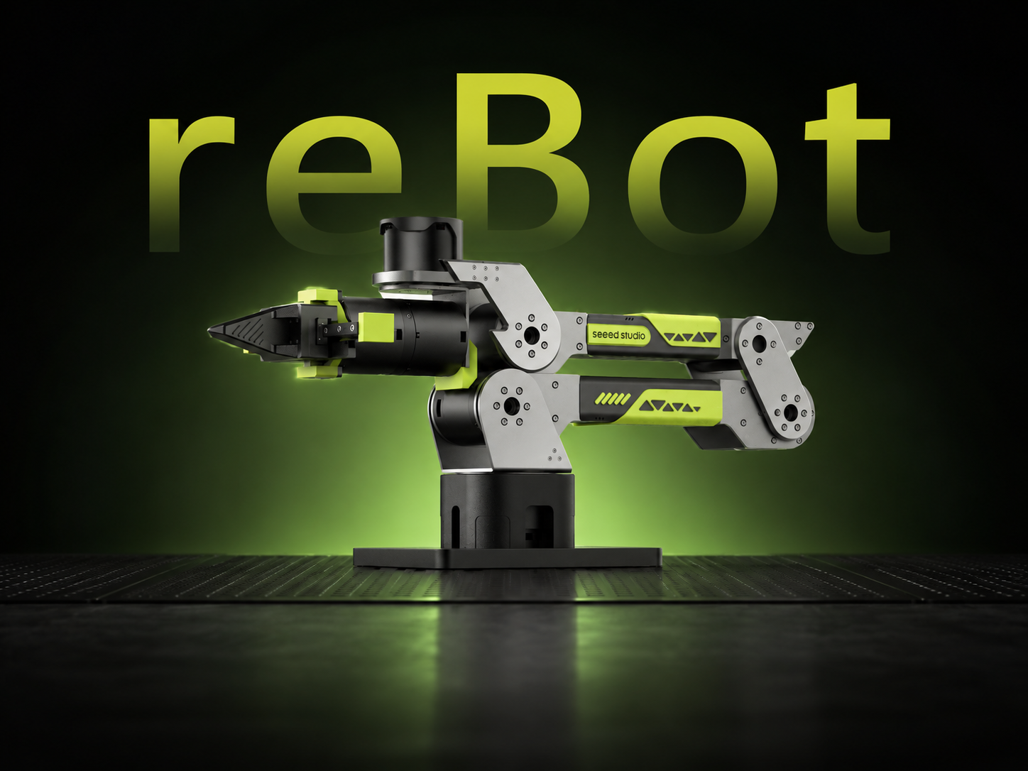




6-DOF Robotic Arm · Multi-Motor Support · Kinematics Solver · Trajectory Planning · Fully Open Source
The reBot Arm project is open source on GitHub—please visit the repository and give it a Star! The repository contains the complete BOM. This guide will help you get started with the B601-DM, from assembly to operation.
Project Introduction
reBot-DevArm (reBot Arm B601 DM and reBot Arm B601 RS) is a robotic arm project dedicated to lowering the threshold for learning embodied intelligence. We focus on "True Open Source" — not just code, we open-source all of the following without reservation:
- 🦾 Open-source robotic arms with two motor versions: We provide all open-source files for RoboStride and Damiao motor versions of the same appearance.
- 🛠️ Hardware blueprints: Sheet metal and 3D printed part source files.
- 🔩 BOM (Bill of Materials): Detailed to every screw's specification and purchase link.
- 💻 Software and algorithms: Python SDK, ROS1/2, Isaac Sim, LeRobot, etc.
If you purchased a pre-assembled kit, please skip directly to the tutorial video in Step 3 at the end of this article and follow along. There is no need to write motor IDs or calibrate zero positions.
It has been verified that virtual machine performance is insufficient for running demos and there are configuration issues. It is recommended to use an Ubuntu physical machine to control the robotic arm.
We recommend installing Ubuntu 24.04 LTS.
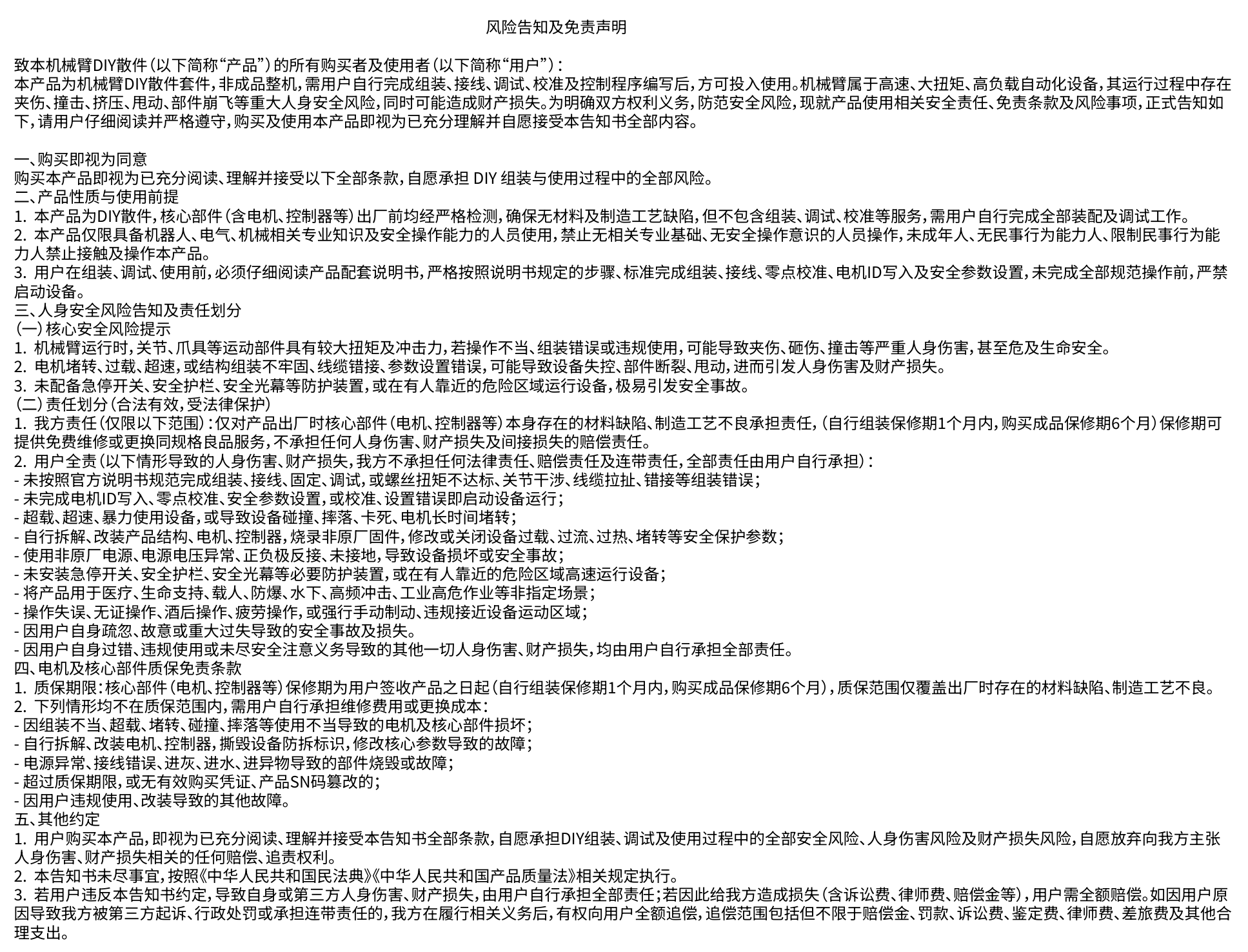
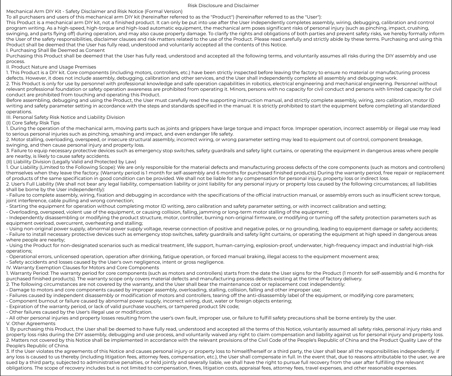
Safety Disclaimer and Risk Notice
About Power Supply
-
The robotic arm is not shipped with a power supply / does not include a power supply by default. You can connect a battery yourself, or purchase our open-source 24V 14.6A MeanWell Power Supply or Amazon, Please do not purchase power supplies from unbranded manufacturers or unsafe channels. Any risks or consequences arising therefrom shall be borne by the individual.
-
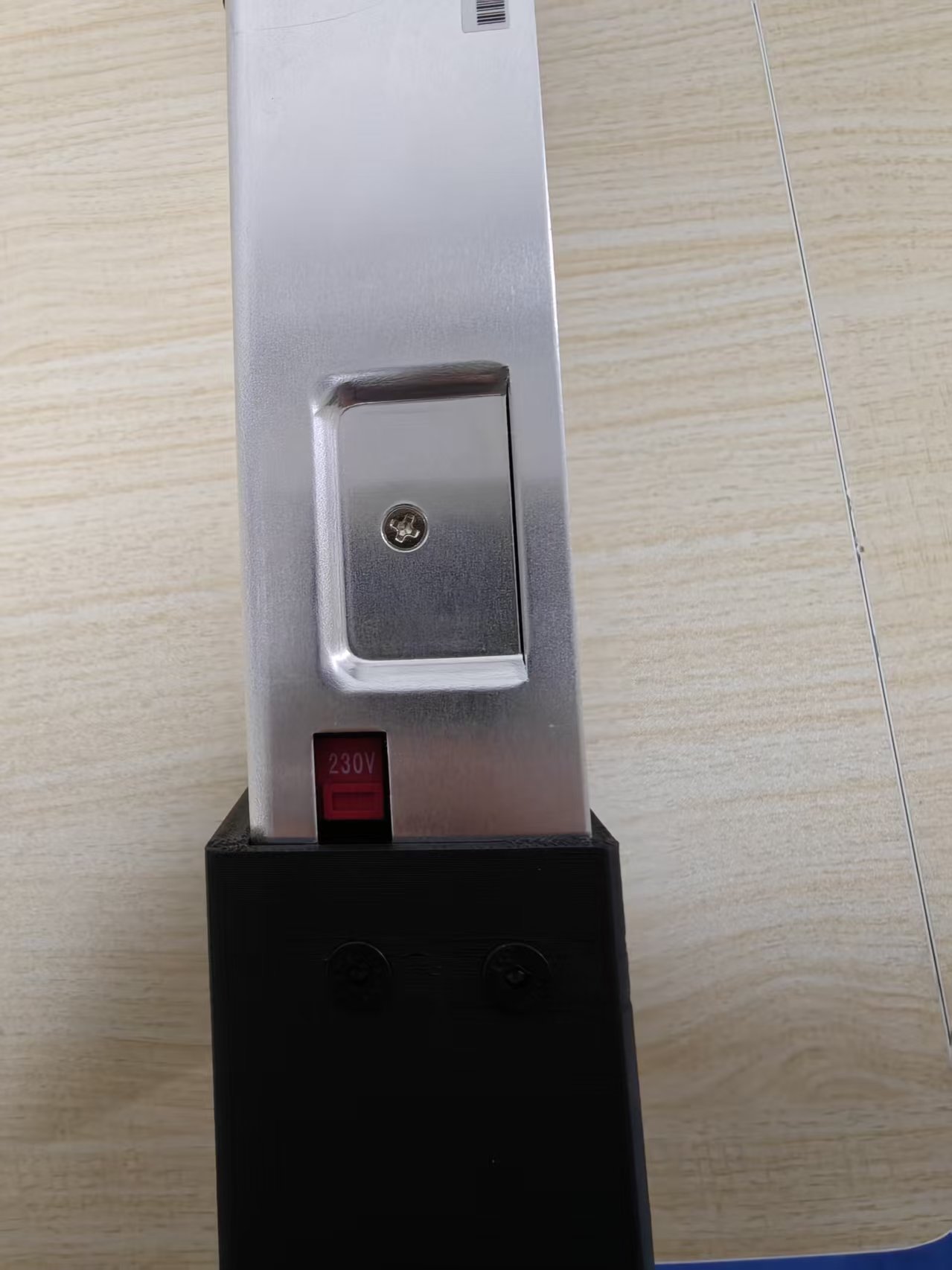
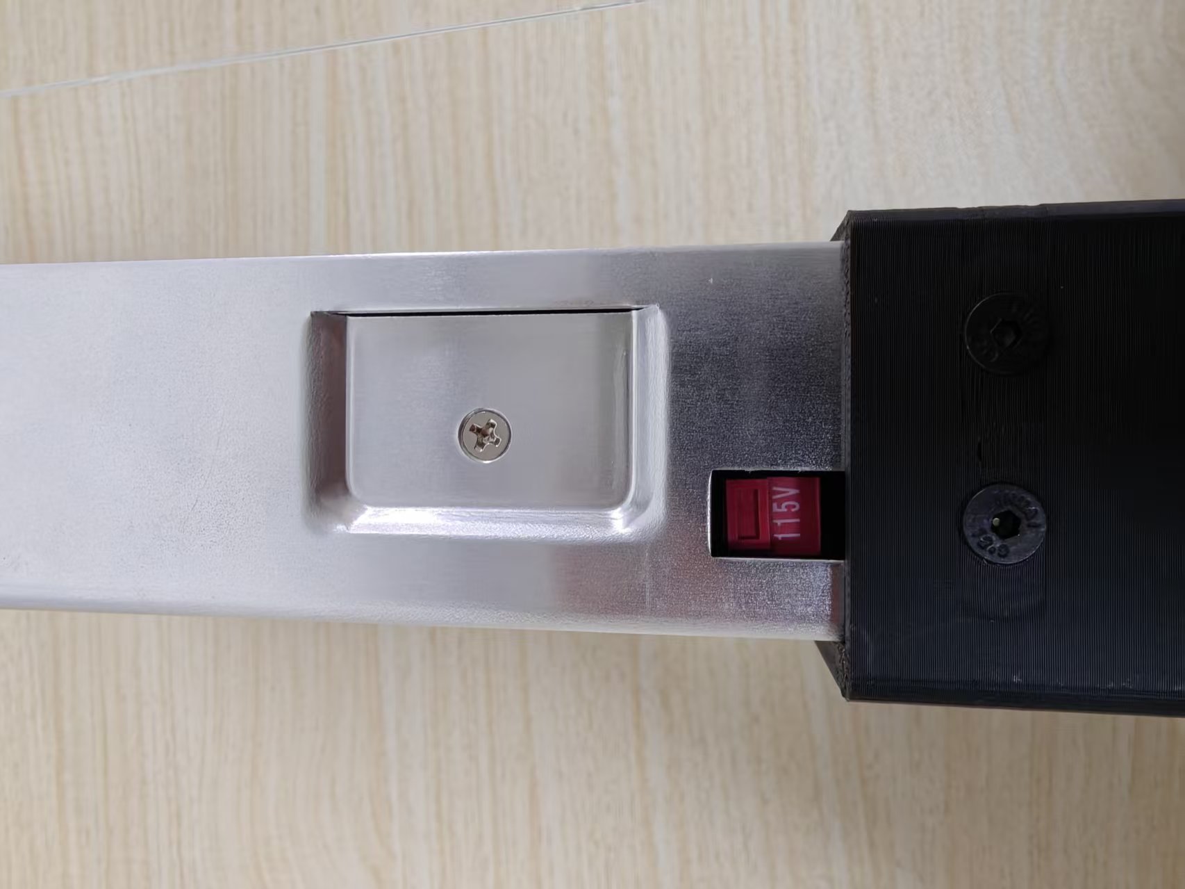
If your household voltage is 220V, set the voltage selector switch on the side of the power supply to 230V. If your household voltage is 110V, switch it to 115V.

Assemble the Power Supply
Alternatively, you can choose our open-source 24V 14.6A MeanWell power supply enclosure for self-assembly. The text instructions and BOM are open-sourced in the GitHub repository (recommended only for developers with relevant power supply assembly experience).
Assembly reference video:
Step 1: Assembly Guide
Before Assembly:
-
Please read the following instructions carefully to ensure a smooth assembly process.
- This kit includes various screws and parts with similar appearances. Verify specifications and orientation before fastening.
- The video was recorded in early April. Minor updates may exist, but assembly remains the same. Refer to shipped parts as final.
- Shipped screws have thread-lock applied. Use proper tools or an electric screwdriver (recommended). Set torque to (3–6 kgf·cm) to avoid stripping. If stripping occurs, stop immediately and replace or realign the screw. Stripped thread-lock screws are difficult to remove and may damage parts.
- Ensure safety during assembly. Avoid pinching or injury. Children must be supervised.
tipReminder: The D4 * 7 between motor 5 and motor 6 in the assembly video does not need to be installed. It's a mistake in the video. If you bought the DIY version of the reBot Arm B601-DM, the 7 D4 * 7 screws are enough for you to complete the assembly.
Wiring tutorial video:
Flexible Gripper Installation
Step 2: Reset Motors ID
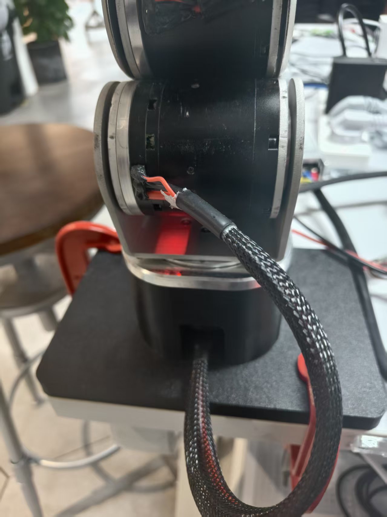
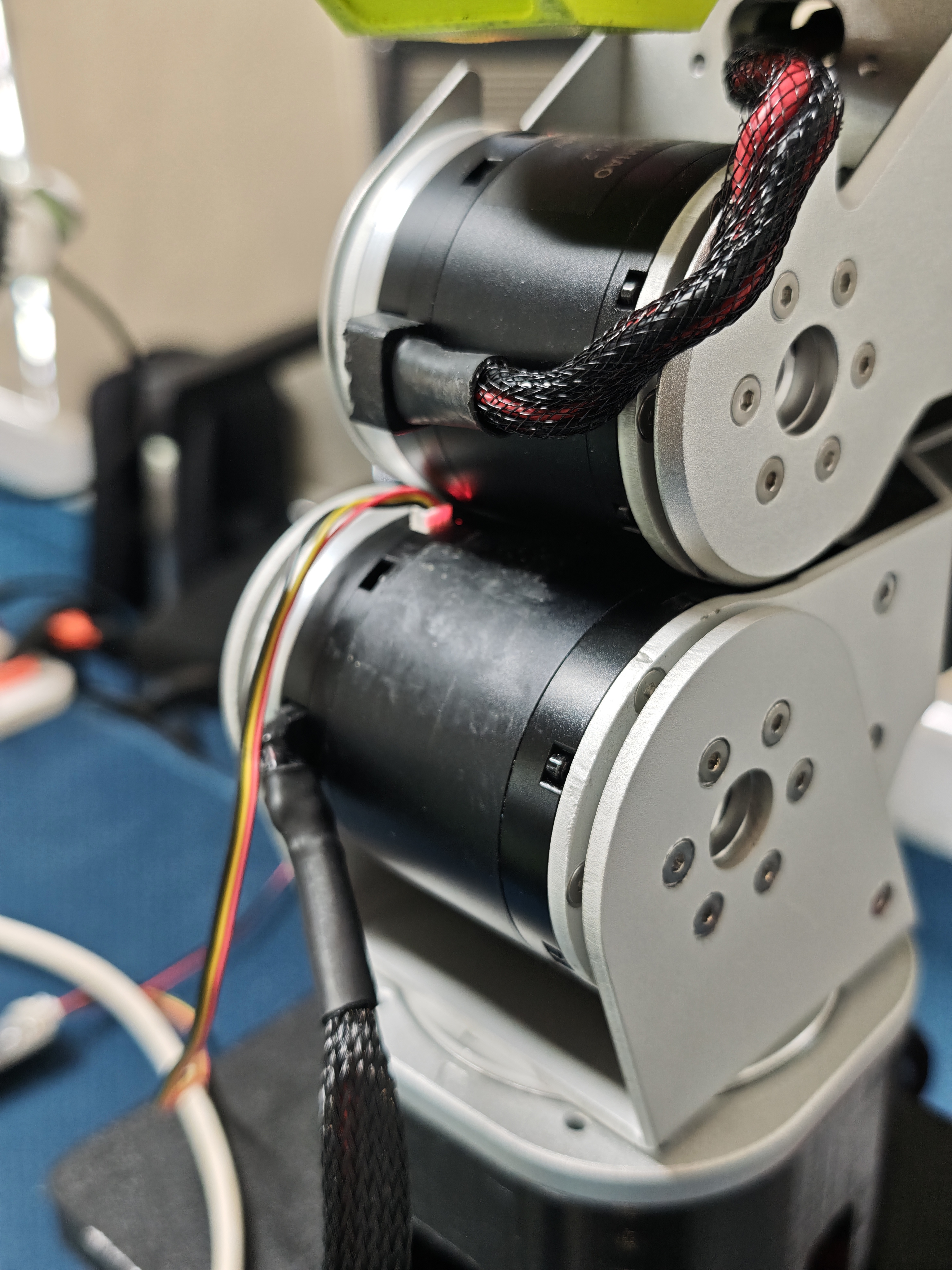
When assembling the robotic arm, do not forget to connect the cable harness between Motor 1 and Motor 2. The exact position is highlighted in the image below. Before switching the 3-pin cable connection, make sure the current motor is disabled and the power is disconnected to avoid hot-plugging or incorrect operation that may cause abnormal motor parameters.
AI AGENT
This section is in beta. Please observe safety precautions during use. If AI suggestions differ from this documentation, follow this guide and seek assistance from our engineers.
Let an AI AGENT assist you through this process. Copy the prompt below to your AI assistant:
Please follow the workflow in AGENTS.md (https://github.com/Welt-liu/reBot-B601-RS-Skills/blob/main/en/AGENTS.md) to help me initialize the robotic arm.
Before Reset Motors:
Before motor parameter configuration, note the following preparations and safety rules:
- Buy 2 tooling clamps (≥3 inches) and a 24V 15A XT30-output switching power supply (use regular brand, no inferior products).
- Keep ≥1m distance during debugging/operation.
- No motor hot-plugging; cut off power before plugging/unplugging XT30 2+2 interface.
- Do not overload/overspeed; check wiring and fasteners before startup; avoid humid/high-temperature/dusty environments.
- Set reasonable program parameters and emergency stop to prevent out-of-control.
- Strictly follow these rules. Seller is not liable for risks/liabilities from illegal operation or personal mistakes.
Preparation List
Hardware
- reBot Arm B601 DM Robotic Arm × 1
- USB-CAN Adapter Board × 1
- Signal-Power Separation Board × 1
- Woodworking Clamps × 2
- USB-C Cable × 1
- 24V 15A Power Supply (XT30 output) × 1
- Power Cord-US \ Power Cord-EU
Computer Requirement
- Dual-boot personal computer (Windows + Ubuntu / macOS)
Software
Write Motor ID and Test Enable
Set the CAN ID and Master ID for each joint motor according to the parameters in the table below:
| Motor Number | Motor Model | CAN ID | Master ID |
|---|---|---|---|
| Motor 1 | J4340P | 0x01 | 0x11 |
| Motor 2 | J4340P | 0x02 | 0x12 |
| Motor 3 | J4340P | 0x03 | 0x13 |
| Motor 4 | J4310 | 0x04 | 0x14 |
| Motor 5 | J4310 | 0x05 | 0x15 |
| Motor 6 | J4310 | 0x06 | 0x16 |
| Motor 7 | J4310 | 0x07 | 0x17 |
The following is an operation example using Motor 1. Please ensure that the CAN ID and Master ID for each joint motor are set correctly according to the table above.
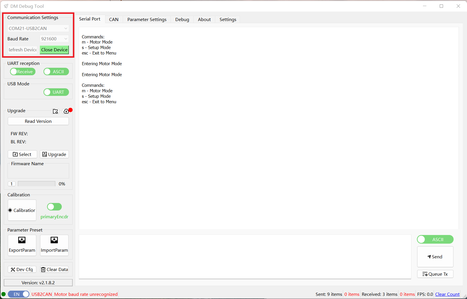
1.Open the DM_Tools host software, select the corresponding USB COM port, and set the baud rate to 921600. Once connected successfully, information will be printed in the Serial interface.
2.Use the 3-pin cable to connect Motor 1 to the USB-CAN adapter board.
3.After connection, enter the Parameter Settings interface. Click Read Parameters to retrieve the current parameters, then set the CAN ID to 0x01 and the Master ID to 0x11.
4.After setting, click Write Parameters to save the parameters.
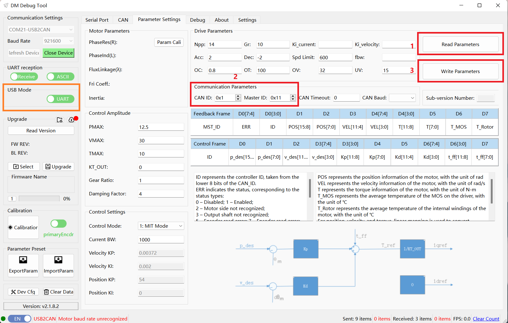
The USB mode in the orange box on the left represents the method used when reading and writing motor parameters on the current settings page.
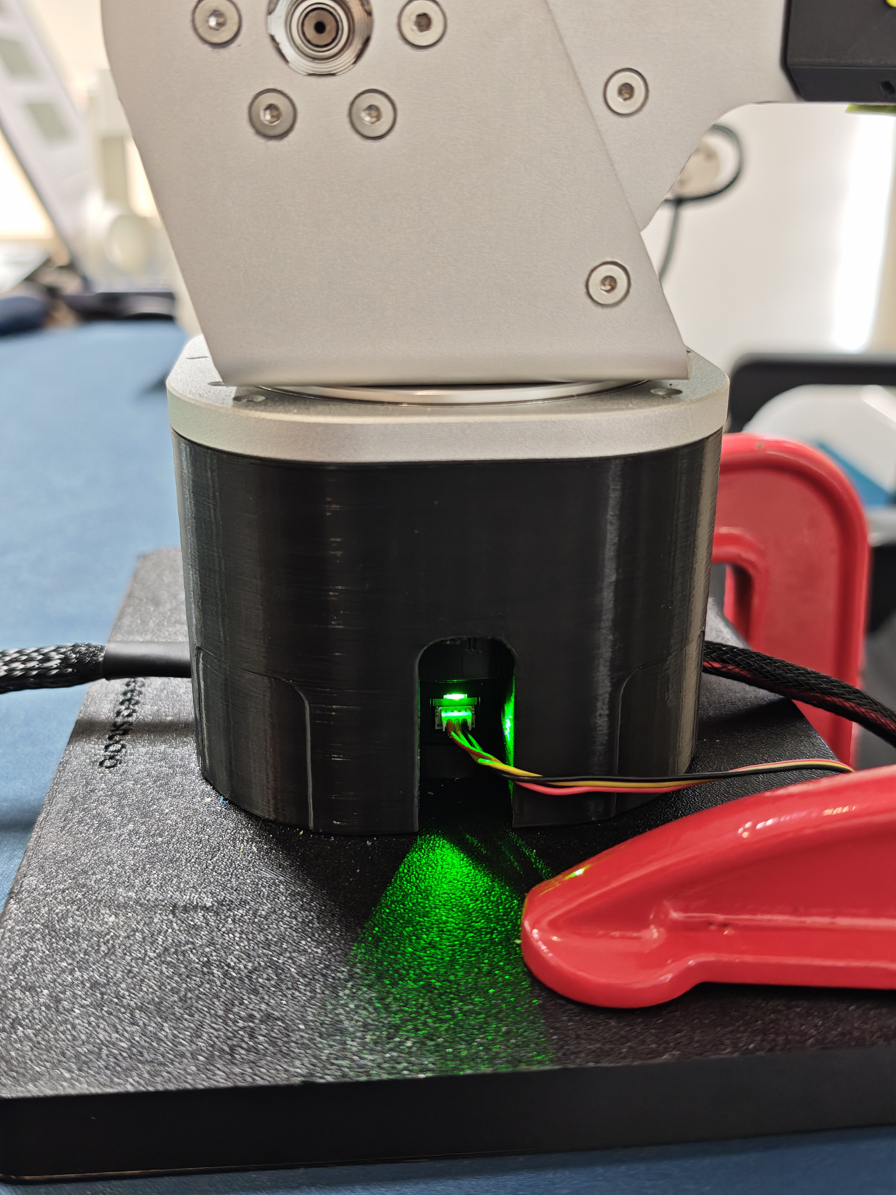
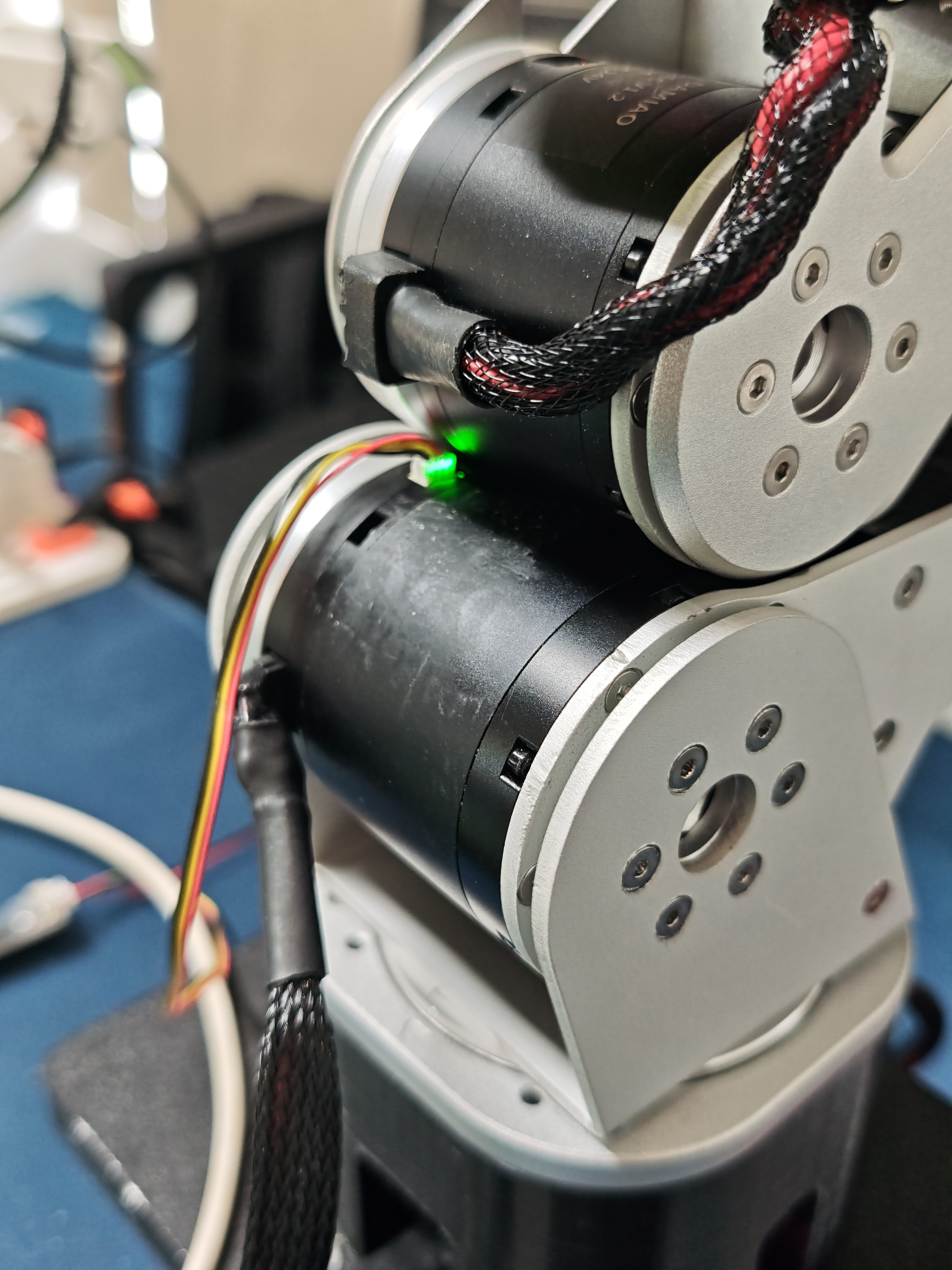
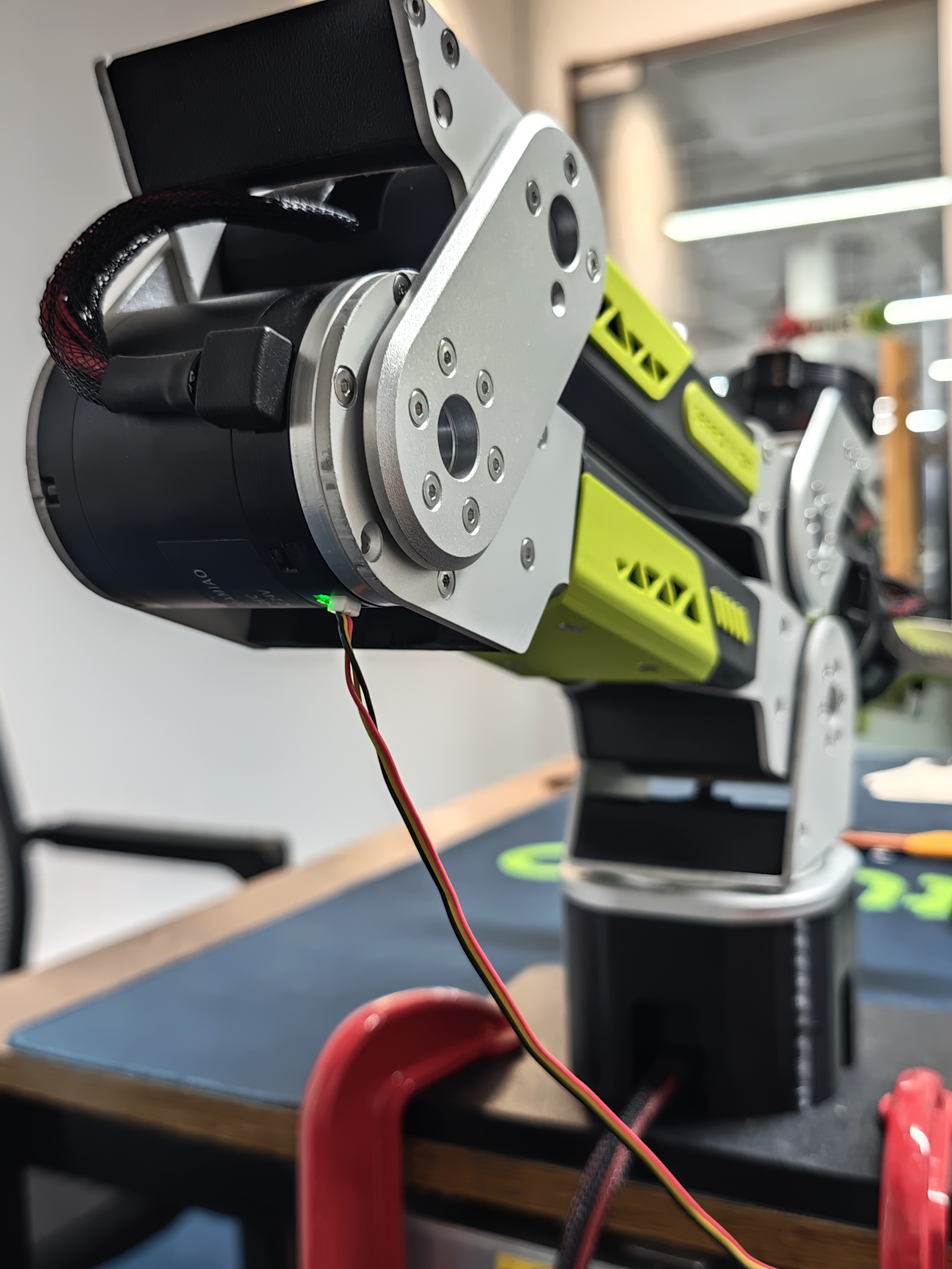
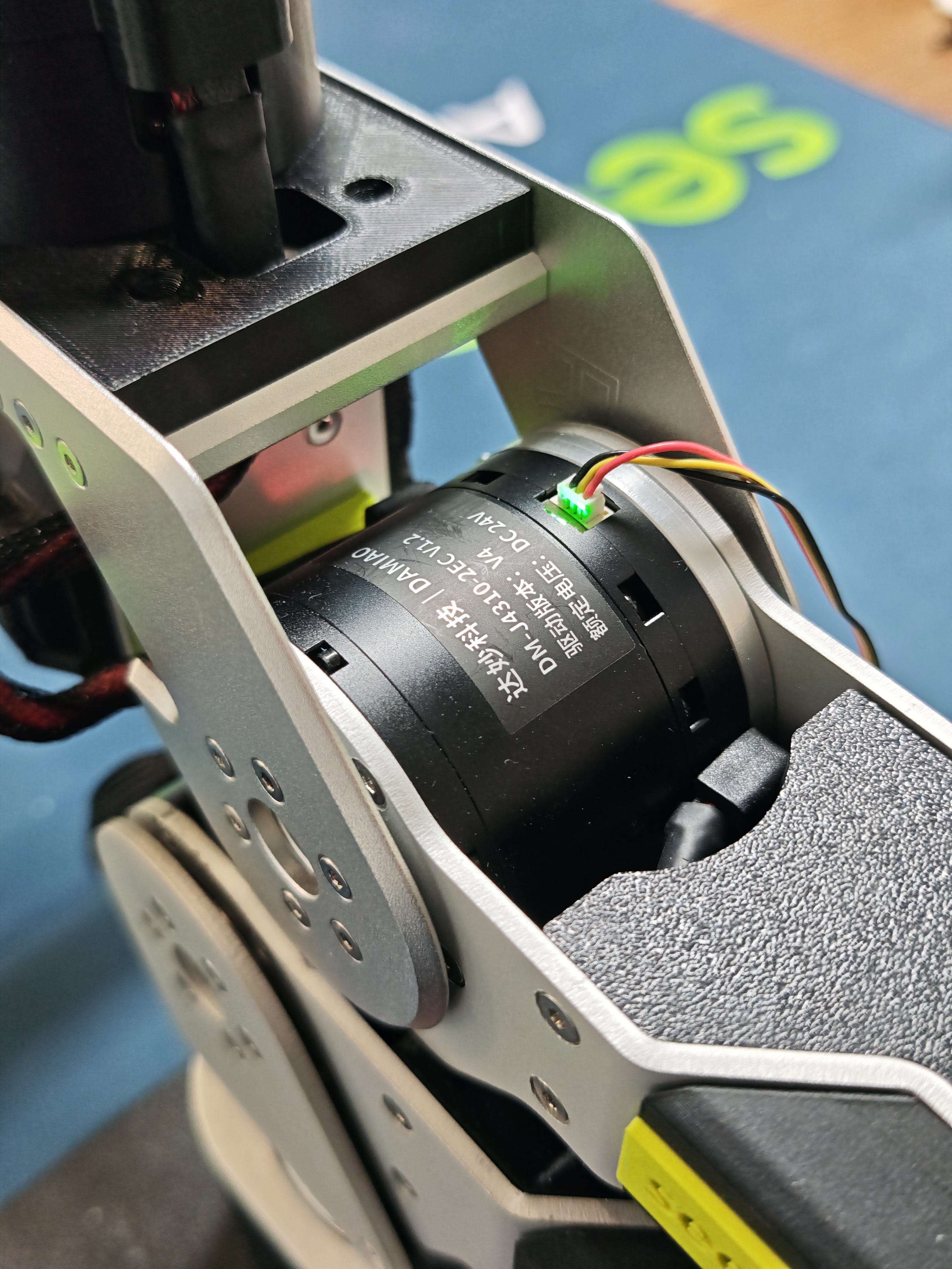
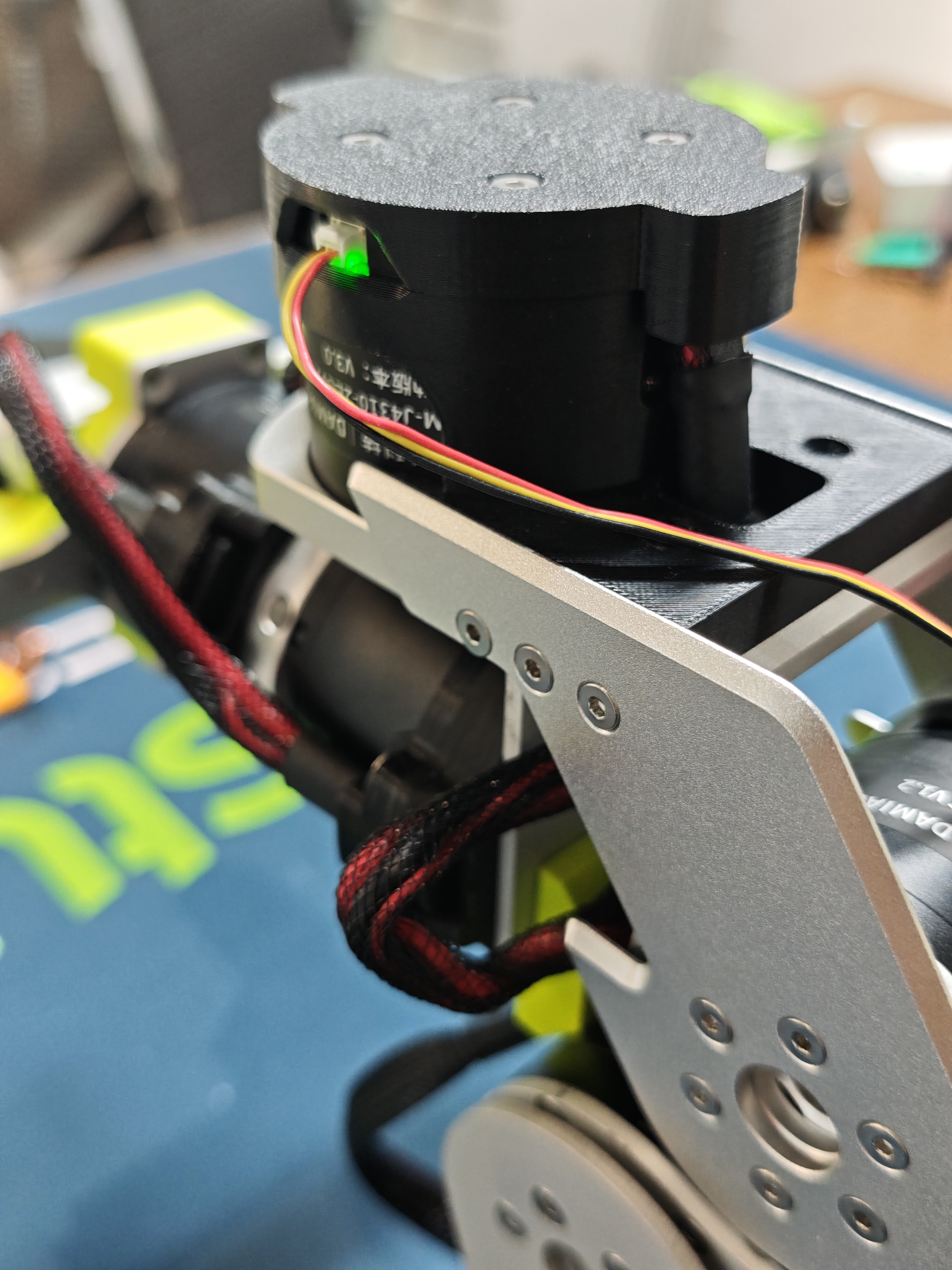
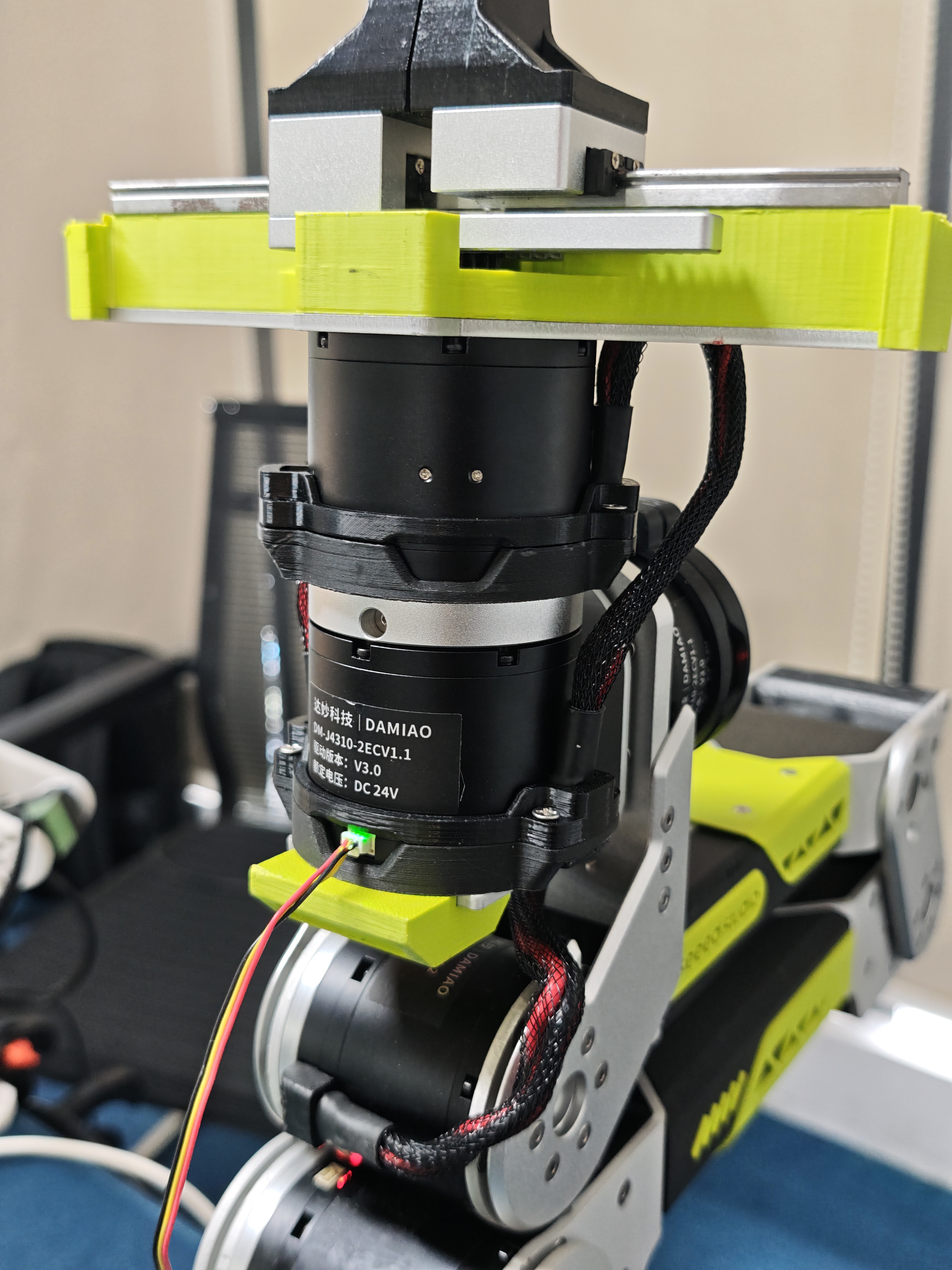
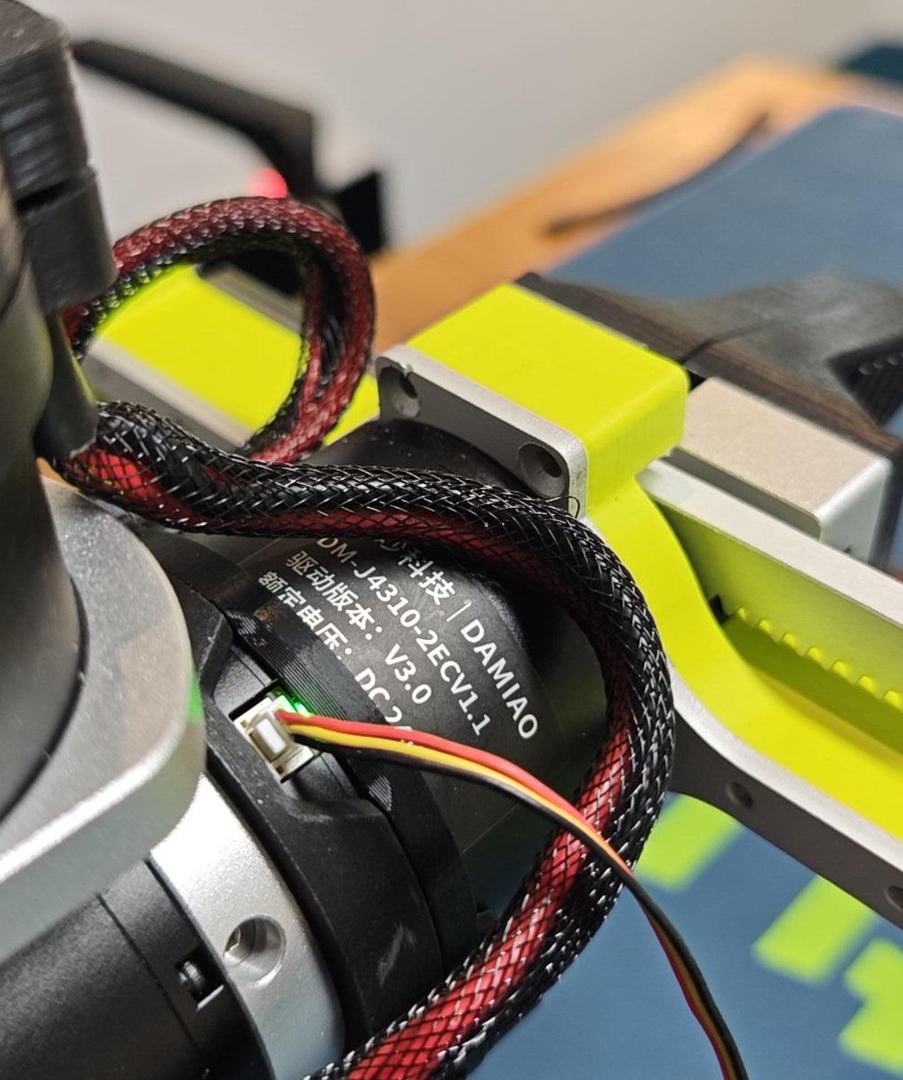
5.Navigate to the Debug interface. After ensuring the CAN ID and Master ID are set correctly, click Enable. The motor indicator light will turn solid green, indicating the motor is enabled. Motor 1 testing is now complete.
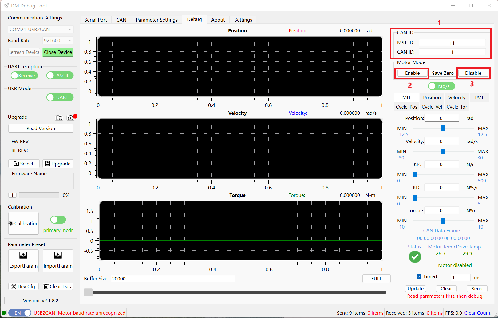
After testing, remember to click Disable to exit the enabled state.
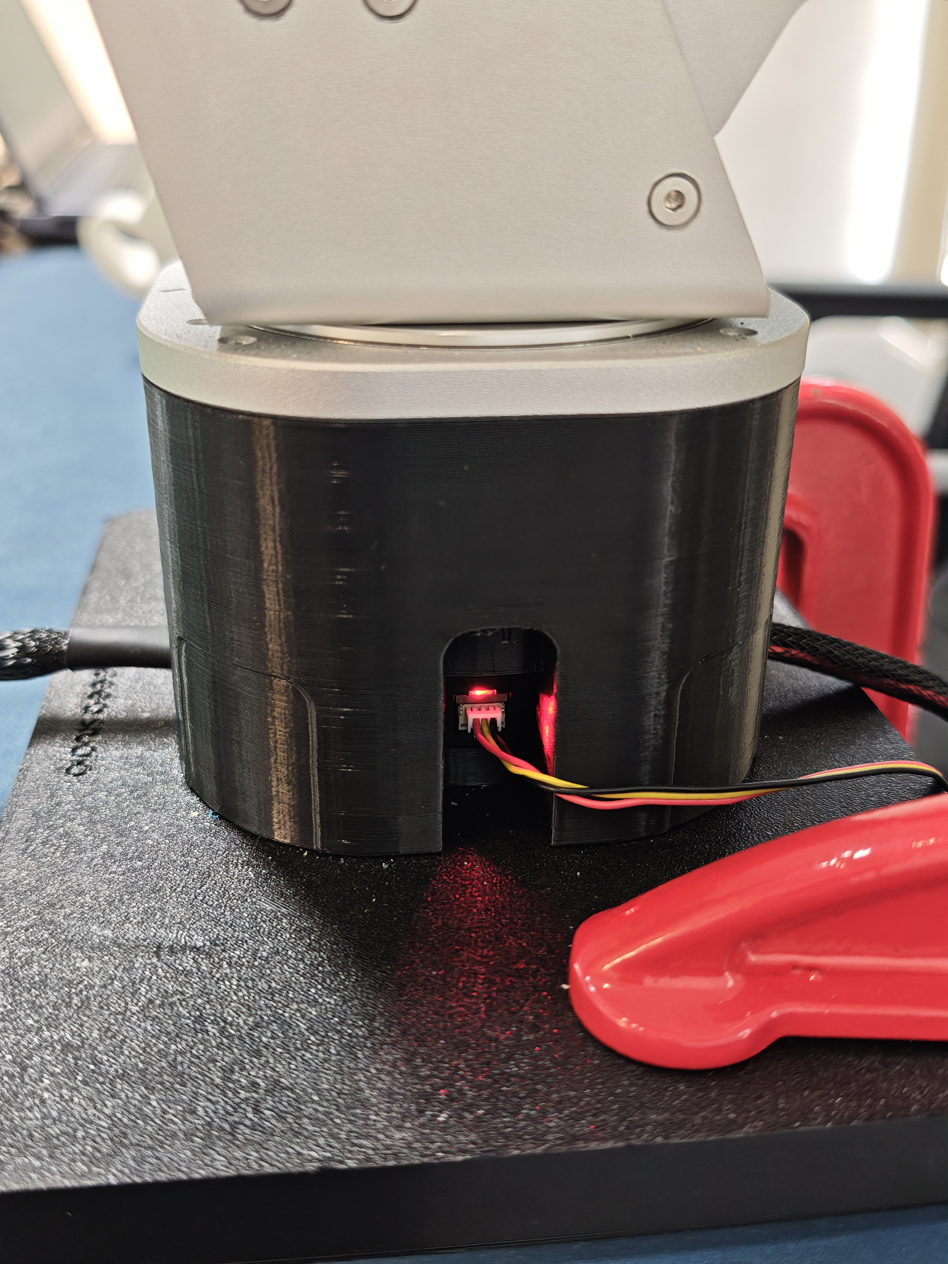
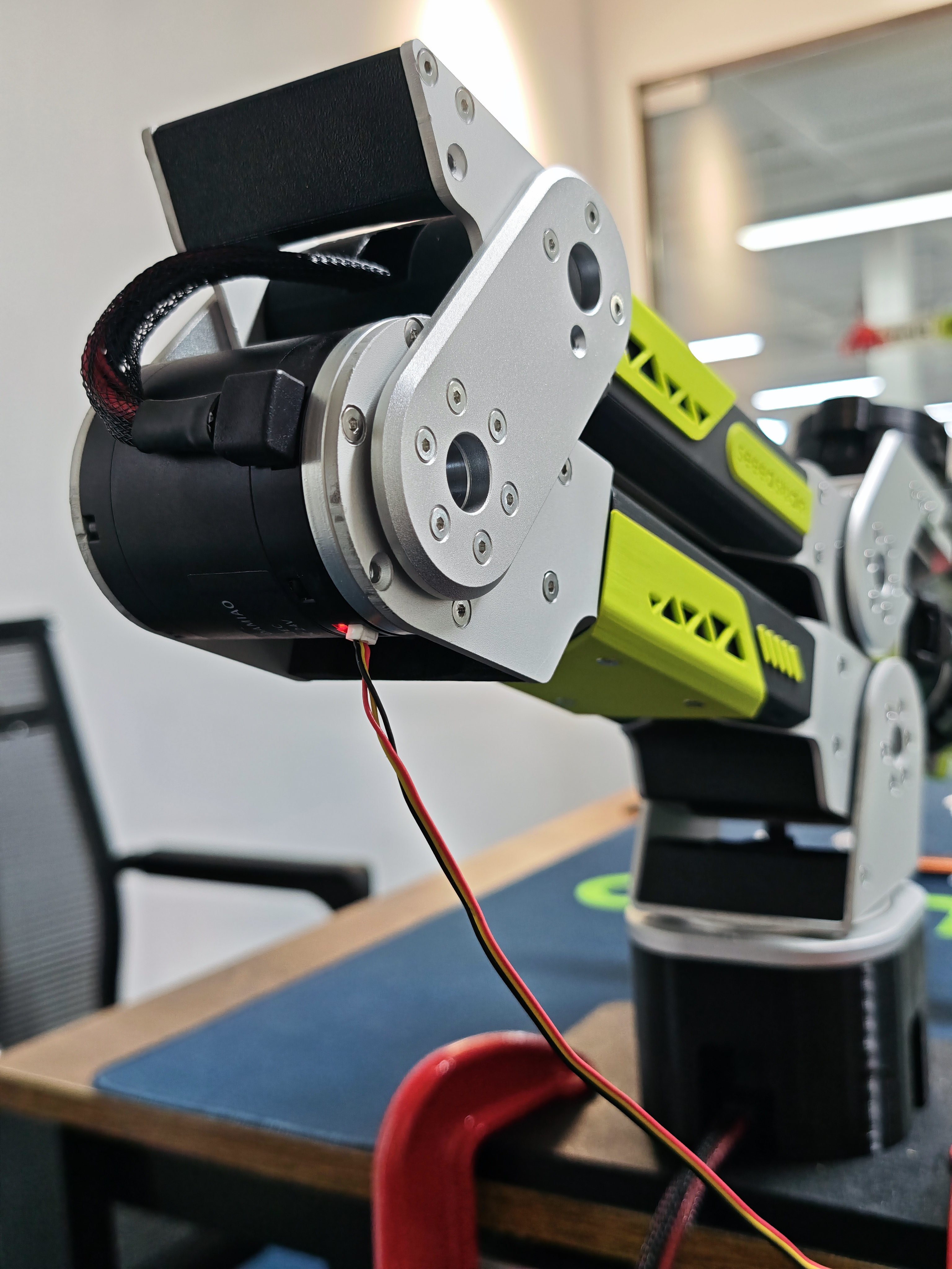
3-pin Cable Connection Points and Enable Effect for Each Motor
| Motor 1 Setup | Motor 2 Setup | Motor 3 Setup | Motor 4 Setup | Motor 5 Setup | Motor 6 Setup | Motor 7 Setup |
|---|---|---|---|---|---|---|
 |  |  | 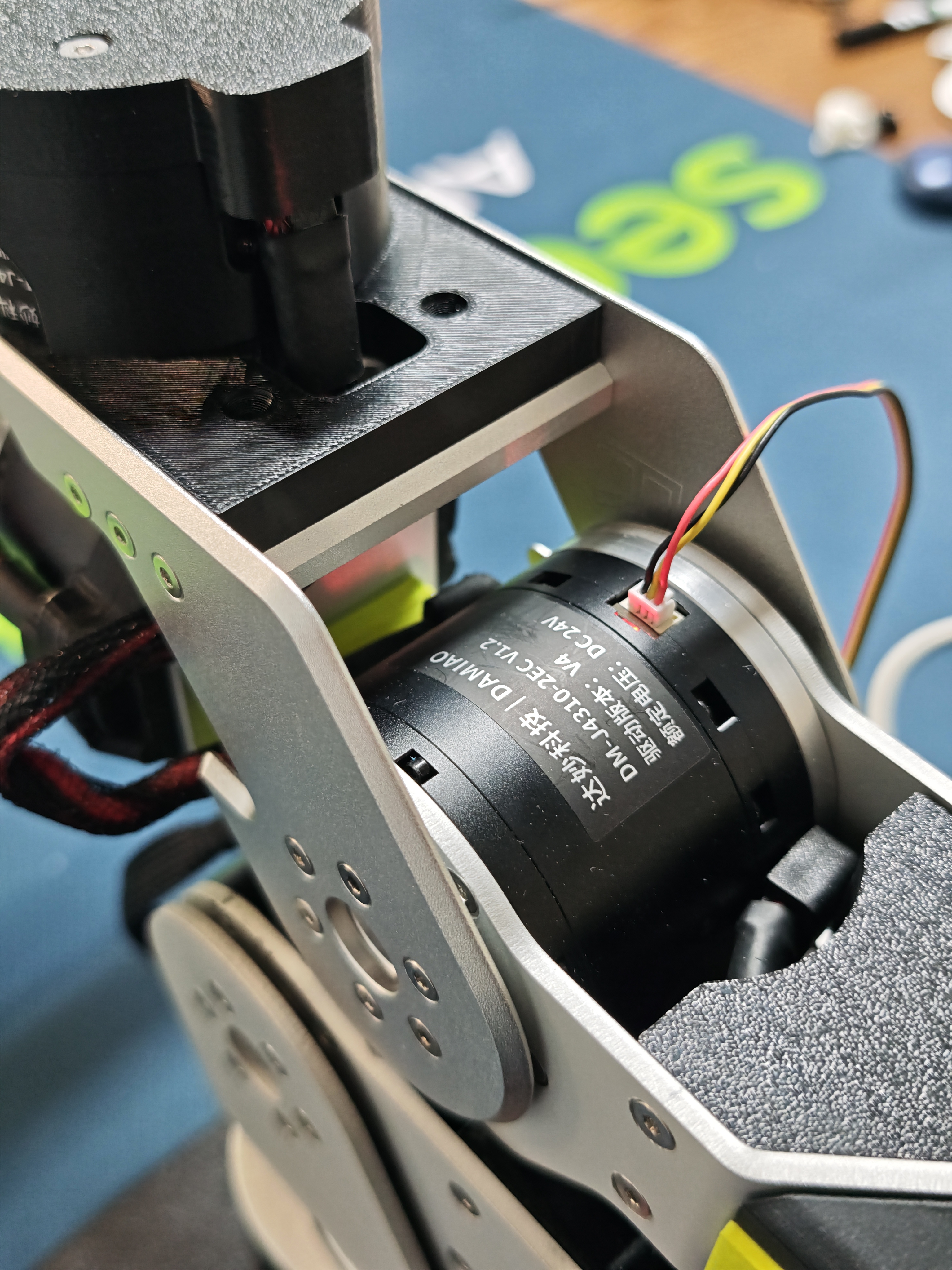 | 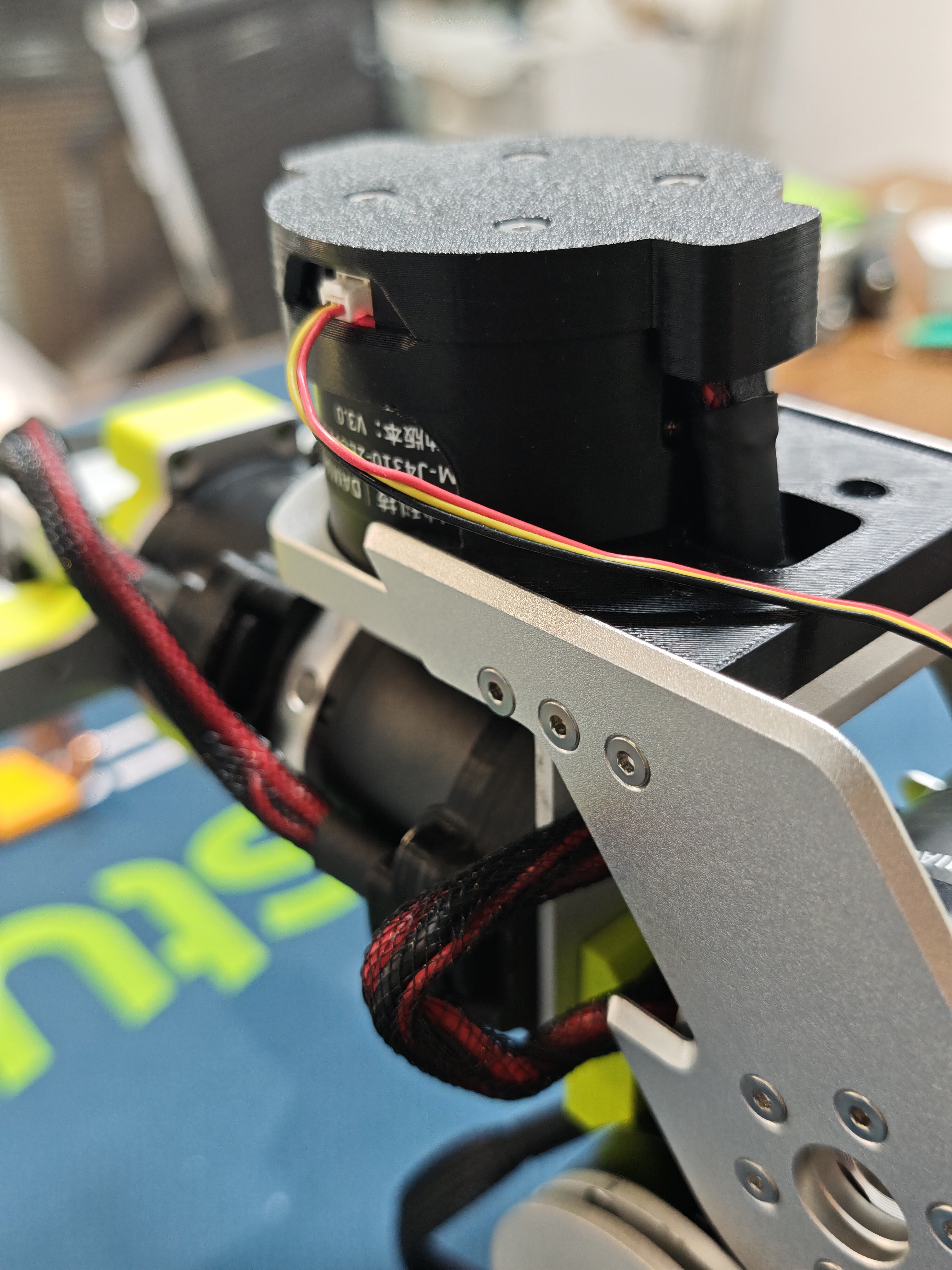 | 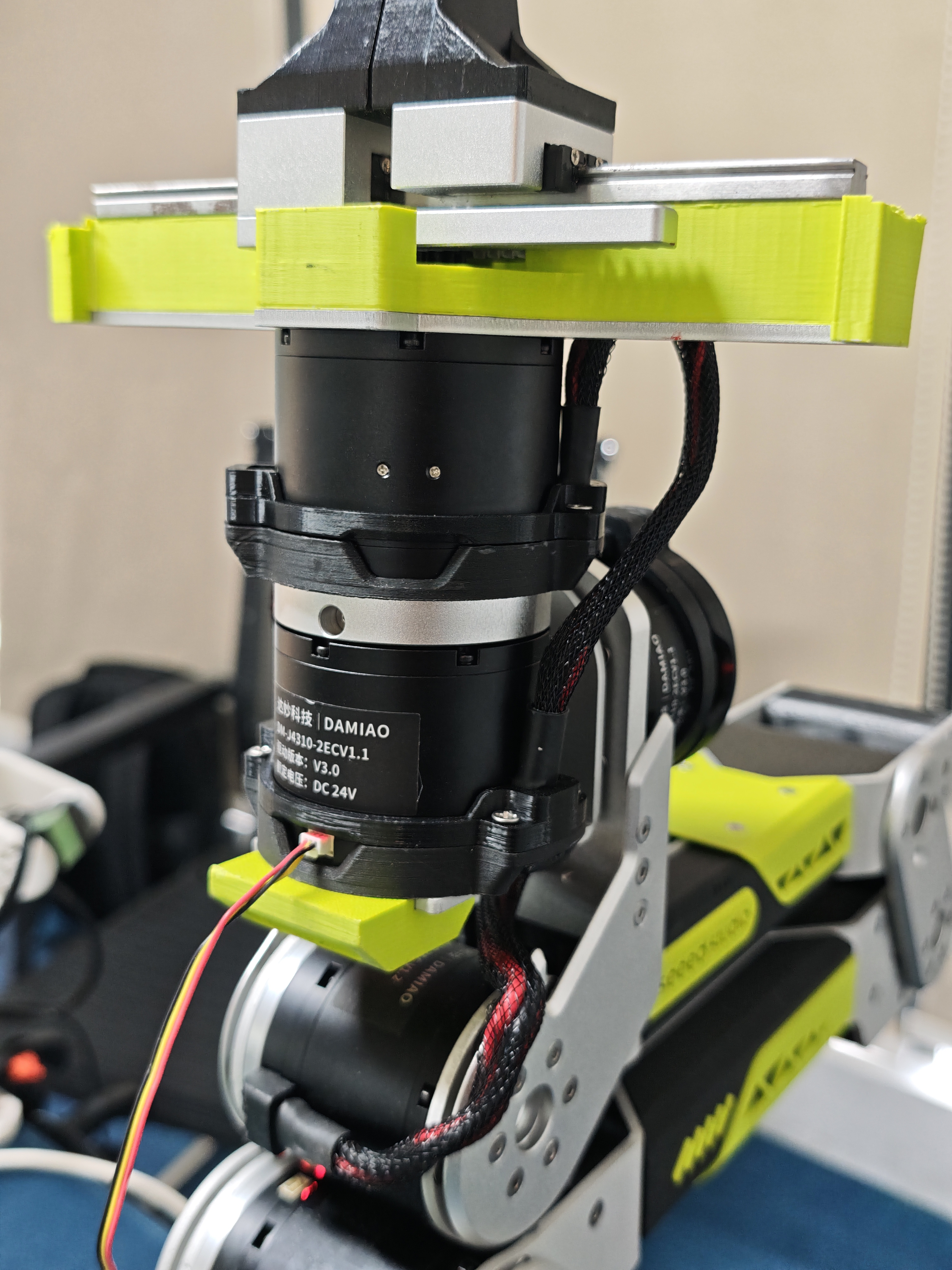 | 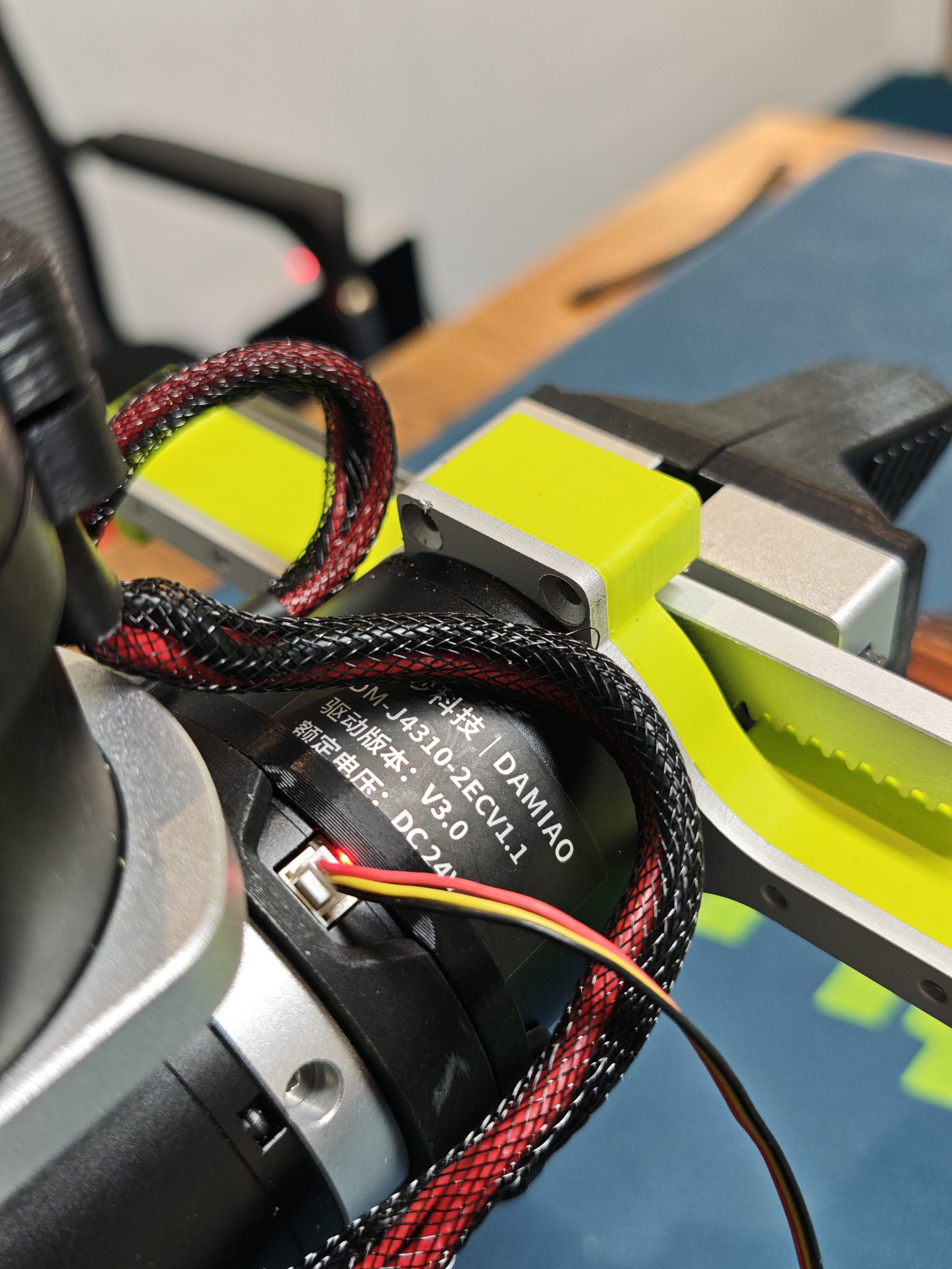 |
| Motor 1 Enabled | Motor 2 Enabled | Motor 3 Enabled | Motor 4 Enabled | Motor 5 Enabled | Motor 6 Enabled | Motor 7 Enabled |
|---|---|---|---|---|---|---|
 |  |  |  |  |  |  |
Step 3: Use MotorBridge to Calibrate the Arm and Complete the First Run
We trust you have completed the robotic arm assembly, zero-point initialization, motor ID configuration, and other setup steps by following the video. You are now ready to officially explore the series of tutorials and tools we have released.
-
Explore our MotorBridge platform, an all-in-one solution supporting an expanding list of motors including Damiao, Robstride, Hightorque, Myactuator, Hexfellow, and more. It is also compatible with continuously updated robotic arms such as reBot. Designed for beginners, we also offer a Python SDK that implements the same functionality for developers.
-
Experience new features and details of MotorBridge for the reBot robotic arm, including one-click zero-point setting, parameter writing, motor control via UI drag-and-drop, and a built-in model visualization interface.
-
This tool is fully compatible with Windows, Ubuntu, and macOS operating systems.
Please refer to the video and text tutorial. Before controlling the robotic arm, you need to reset the zero point again.
Software Setup and Calibration Workflow
Follow these steps in order to install Miniforge and create an isolated Python environment for reBot development.
Install Miniforge
Step 1
Download and install Miniforge for your operating system:
- Ubuntu\Jetson\Raspberry Pi
- macOS
- Windows
wget "https://github.com/conda-forge/miniforge/releases/latest/download/Miniforge3-$(uname)-$(uname -m).sh"
bash Miniforge3-$(uname)-$(uname -m).sh
During installation, press Enter to continue, enter yes to accept the terms, and enter yes when asked whether to initialize Conda.
Restart the terminal and verify the installation with conda --version.
conda is not foundLoad Miniforge and initialize Bash:
source ~/miniforge3/etc/profile.d/conda.sh
conda init bash
curl -L -O "https://github.com/conda-forge/miniforge/releases/latest/download/Miniforge3-MacOSX-$(uname -m).sh"
bash Miniforge3-MacOSX-$(uname -m).sh
During installation, press Enter to continue, enter yes to accept the terms, and enter yes when asked whether to initialize Conda.
Restart the terminal and verify the installation with conda --version.
conda is not foundLoad Miniforge and initialize Zsh, the default shell on current macOS versions:
source ~/miniforge3/etc/profile.d/conda.sh
conda init zsh
Open the Miniforge Releases page, find the latest Miniforge3-Windows-x86_64.exe, and download it.
Git Bash users: If conda is not found, load Conda first:
# Temporary: replace <install_path> with the actual path
source <install_path>/etc/profile.d/conda.sh

# Permanent: add it to bashrc once
echo 'source <install_path>/etc/profile.d/conda.sh' >> ~/.bashrc
source ~/.bashrc
For PowerShell, initialize Conda with:
conda init powershell
Environment Setup
Step 2
Create a virtual environment with Python 3.12:
conda create -y -n rebot python=3.12
Then activate your virtual environment, you have to do this each time you open a shell to use rebot:
conda activate rebot
Install Motorbridge
Step 3
Note for macOS users:
If you experience low frame rates during teleoperation on macOS, it may be caused by an outdated WCH CH34x driver. For macOS 10.14 and later, the system includes a built-in AppleUSBCHC0M driver. You can uninstall the old driver and switch to the macOS built-in driver, which should effectively improve frame rates.
After activating the reBot virtual environment, run the following command to install motorbridge:
pip install motorbridge
Connect the reBot Arm
Step 4
After connecting the robotic arm to your computer through USB cable and turning on its power supply, you need to configure 666 access permissions for the serial port.(Windows systems do not require permission configuration; you may skip this step.)
sudo chmod 666 /dev/ttyACM*
Start MotorBridge
Step 5
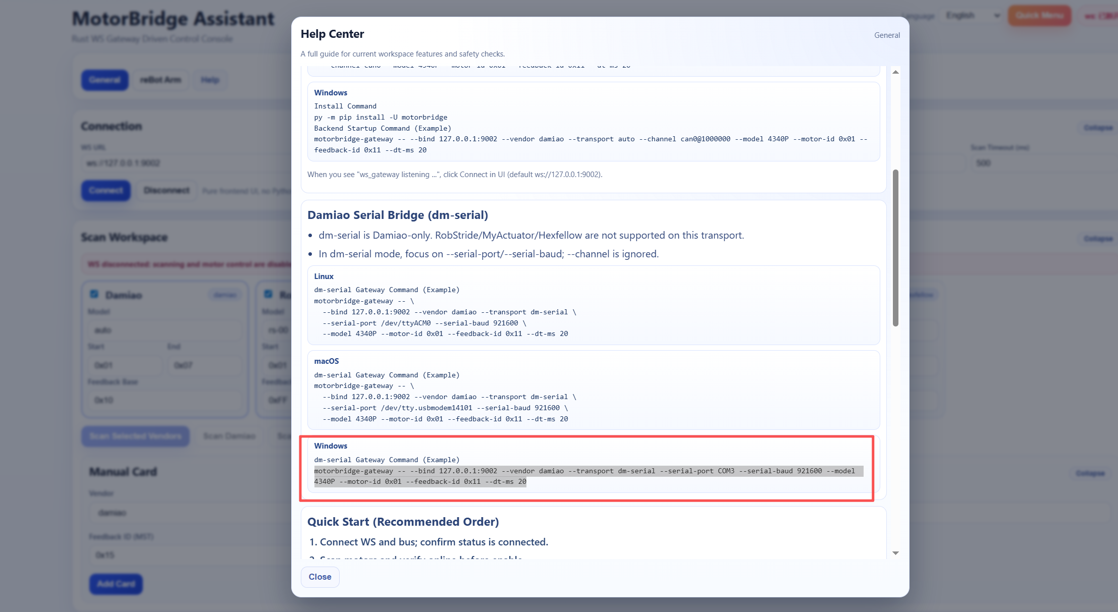
Open the address motorbridge-studio in your browser, click the Help option, copy the corresponding command based on your operating system and driver board, verify the IP address and port number, then press Enter in the terminal to run it.
For example on Windows:
motorbridge-gateway -- --bind 127.0.0.1:9002 --vendor damiao --transport dm-serial --serial-port COM3 --serial-baud 921600 --model 4340P --motor-id 0x01 --feedback-id 0x11 --dt-ms 20
FAQ
1. Loud abnormal noise occurs immediately after motor startup
- This issue usually happens when parameter calibration is accidentally triggered during ID configuration, which overwrites factory preset parameters such as motor inertia. Use DM_Tools_v.1.8.0.1.exe (Windows-only) available at: https://files.seeedstudio.com/wiki/robotics/projects/rebot_arm/DM_Tools_v1.8.0.1.exe Export complete parameters from an intact motor of the same model via the host software, import these parameters into the faulty unit, update its corresponding CAN ID, save the written parameters, then proceed with zero-point calibration.
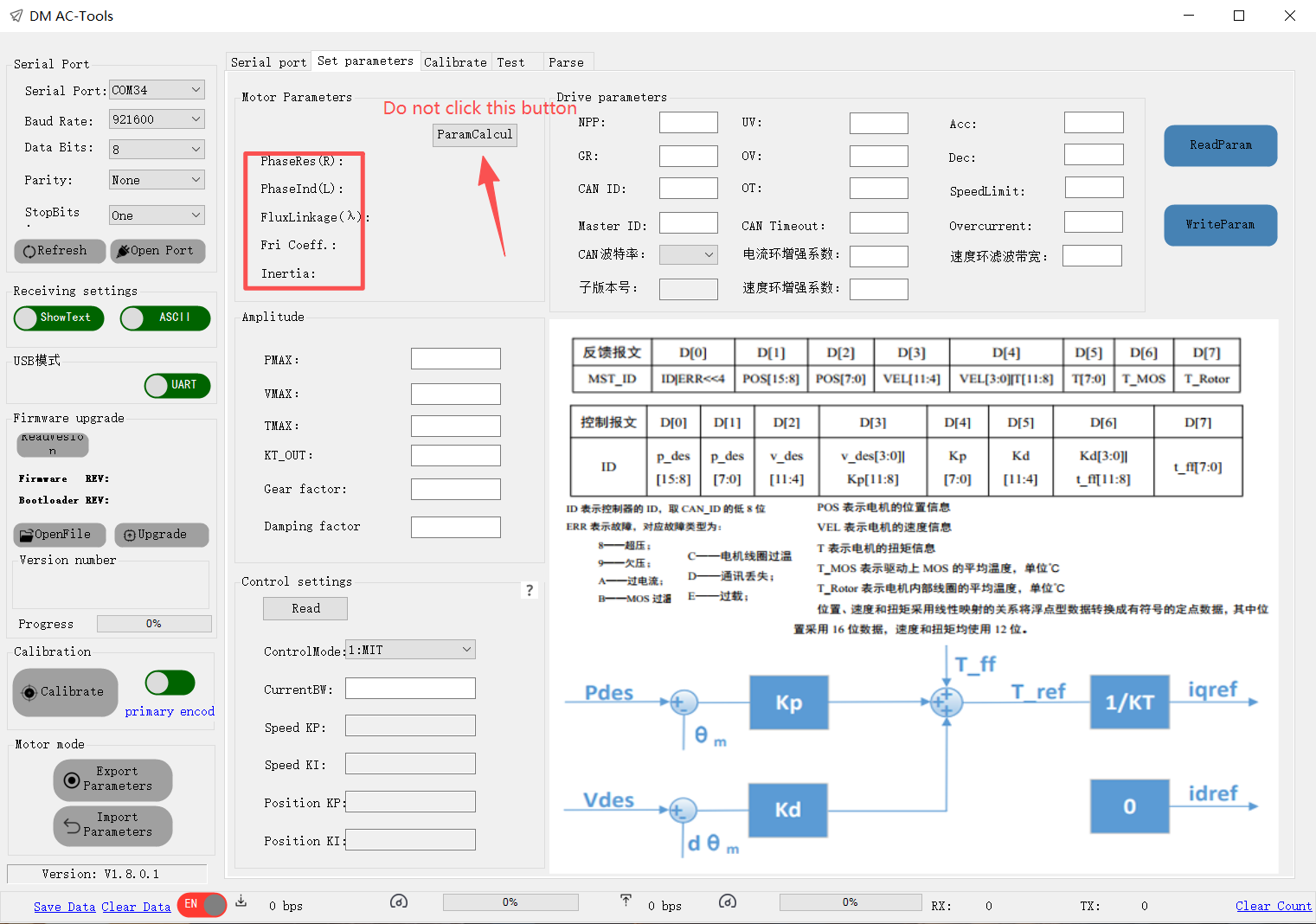
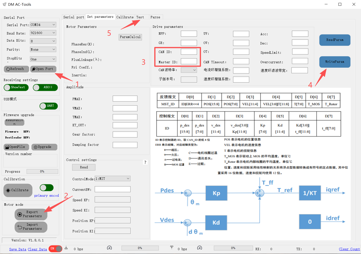
DM4310 Default Parameters DM4340P Default Parameters
2. All motors share identical CAN IDs
- When performing zero-point calibration via DM_Tools_v.1.8.0.1.exe (Windows-only), avoid clicking the Read or Set buttons next to the CAN ID field. The debug interface communicates over the CAN bus; clicking Set will unify the CAN ID for every motor connected on the CANBUS.