4. Fundamentals of Robotic Arms and Joint Actuators
Chapter 4 of the Seeed Embodied Intelligence Beginner's Course — fundamentals of robotic arms and joint actuators, including safety ranges, structure, reducers, encoders, and DM/RS motor control modes.
4.1 Robotic Arm Safety Range and Workspace
4.1 Robotic Arm Safety Range and Workspace
Understanding the parameters in the table below is the foundation for safely using a robotic arm:
-
Reach defines the safety boundary of the robotic arm and must not be exceeded. The reach range defines the safe workspace, preventing the robotic arm from colliding with equipment, fences, or personnel during motion.
-
Rated load sets the baseline for safe and efficient operation and must not be exceeded over long periods. Ignoring the rated load is extremely dangerous. Operating beyond the rated load will directly lead to: insufficient motor and joint torque, component overheating and shortened lifespan, and sudden mechanical failures.
-
Maximum load marks the absolute physical red line that must never be touched — it is a one-time strength limit.
Treating the maximum load as a daily usage standard is extremely dangerous. This means every component of the robotic arm is operating at the edge of structural strength, and any minor impact or posture change could lead to catastrophic structural failure, such as joint fracture or robotic arm collapse.
| Name | reBot Arm DM | reBot Arm RS |
|---|---|---|
| Zero Position Posture | 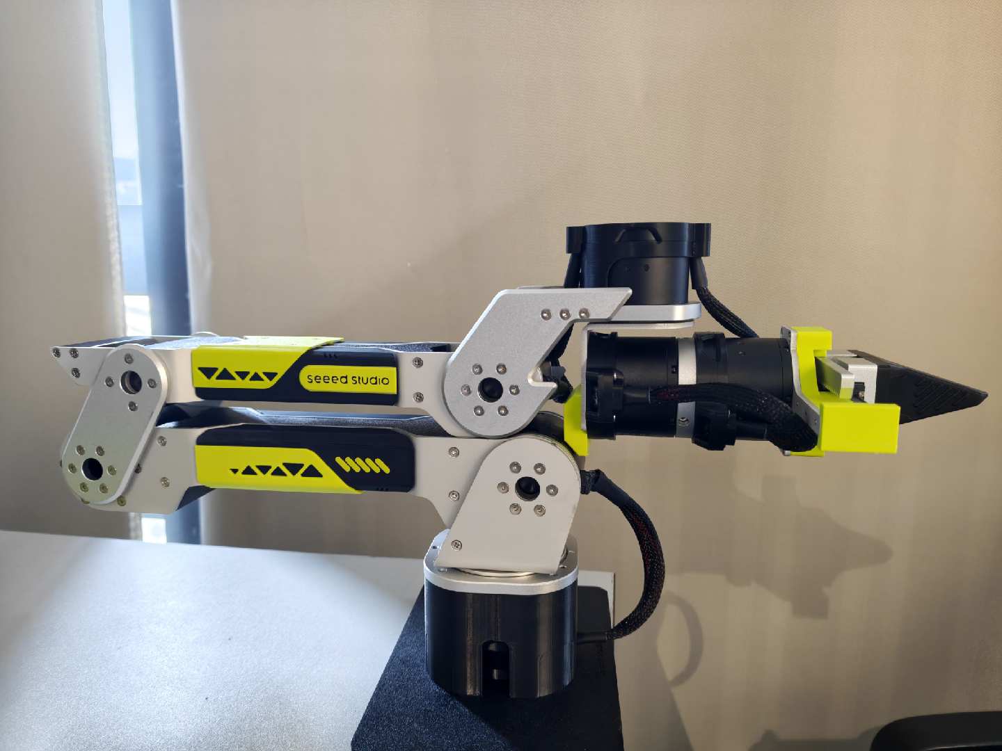 | 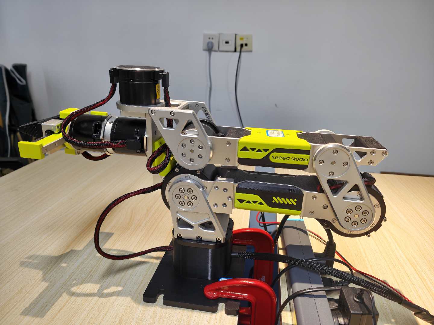 |
| J1 Joint Range | -150° ~ +150° | -150° ~ +150° |
| J2 Joint Range | -220° ~ 0° | -220° ~ 0° |
| J3 Joint Range | -220° ~ 0° | -220° ~ 0° |
| J4 Joint Range | -90° ~ +90° | -90° ~ +90° |
| J5 Joint Range | -90° ~ +90° | -90° ~ +90° |
| J6 Joint Range | -180° ~ +180° | -180° ~ +180° |
| Gripper Range | -325° ~ 0° | -345° ~ 0° |
The zero position posture of the robotic arm is the absolute reference for all motion planning and position calculation. When the robotic arm needs to move to a certain point, it essentially calculates how much each joint needs to rotate from the zero position starting point. Therefore, when setting the zero point for each joint motor and initializing the robotic arm, this posture should be maintained.
Mechanical limits are physical hard boundaries determined by the mechanical structure itself and cannot be changed. They act like physical stoppers, fundamentally limiting the rotation angle range of the joints. This prevents the robotic arm from over-rotating due to loss of control, which could cause damage to its own structure or collision with surrounding equipment.
Even though the joints of the robotic arm all have mechanical limits, you should still pay attention to the motion range of different joints to prevent joint motors from stalling for extended periods due to exceeding the motion range.
4.2 Introduction to the Basic Structure of a Robotic Arm
4.2 Introduction to the Basic Structure of a Robotic Arm
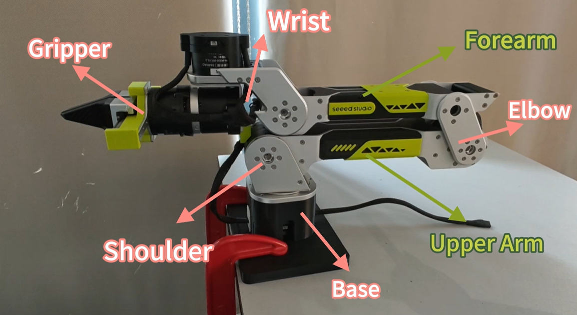
| Name | Position | Motion Axis | Function |
|---|---|---|---|
| Base | The part where motor 1 is fixed | Rotates about the base vertical axis (Z-axis) | Enables the entire robotic arm to rotate horizontally |
| Shoulder | The protruding part containing motor 2 | Rotates about the shoulder horizontal axis (Y-axis) | Enables the upper arm to pitch forward/backward or lift up/down relative to the shoulder |
| Upper Arm | The part connecting the shoulder joint and elbow joint | Rotates about the elbow horizontal axis (Y-axis) | Enables the forearm to bend or extend relative to the upper arm |
| Elbow | The part containing motor 3, located at the junction of the upper arm and forearm | Rotates about the wrist horizontal axis (Y-axis) | Enables the wrist to swing up and down; together with Wrist Yaw, jointly determines the pointing direction of the robotic arm end in space |
| Forearm | The part connecting the elbow joint and wrist joint | Rotates about the wrist vertical axis (Z-axis) | Enables the wrist to swing left and right; together with Wrist Flex, jointly determines the pointing direction of the robotic arm end in space |
| Wrist | The part containing motors 4, 5, and 6, located between the end gripper and forearm | Rotates about the wrist center axis (X-axis) | Enables the wrist end to rotate about its own central axis |
| Gripper | The part containing motor 7, mounted on the wrist | Translational opening/closing | Enables the robotic arm to grasp objects |
4.3 Joint Actuator
4.3 Joint Actuator
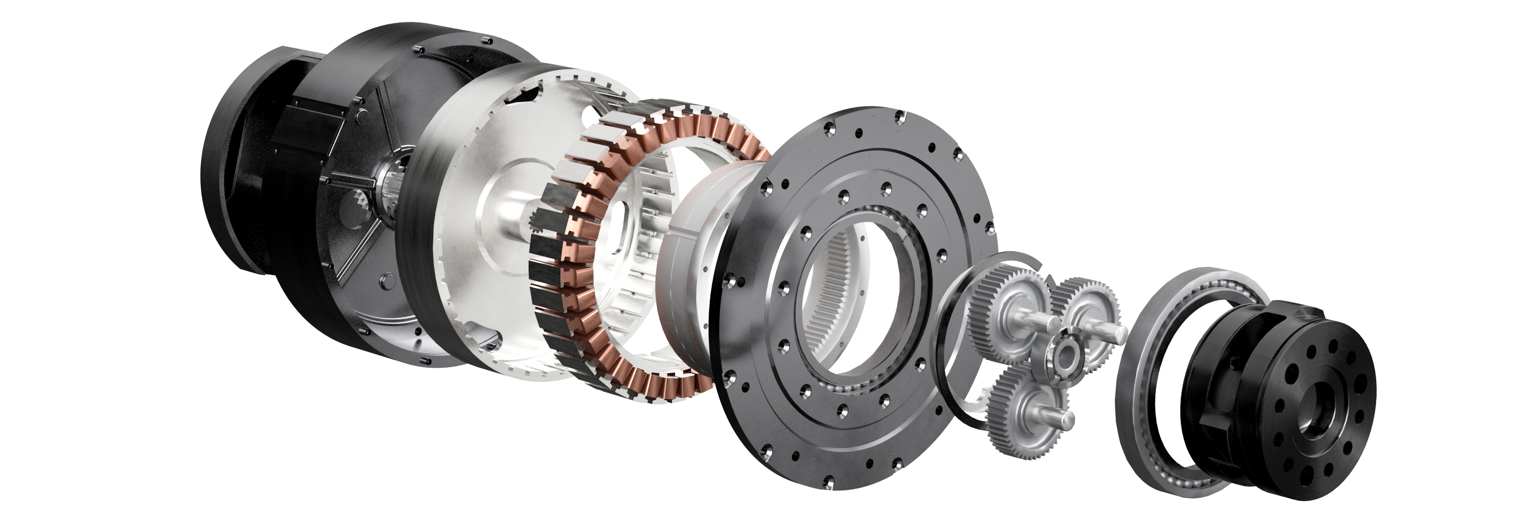
A joint actuator consists of driver → motor → reducer → bearing/output flange → robot link, while at the same time encoder/torque sensor → controller → driver forms closed-loop control.
4.4 Reducer
4.4 Reducer
The original torque output by a motor is usually very small, but through gears with a reduction ratio i, the output torque is amplified by a factor of i.
- Without a reducer, to output large torque, the iron core and magnets must be increased, which would make the motor volume very large, causing costs and weight to soar.
- A reducer is the optimal physical lever that trades high rotational speed for large torque.
- The motor rotor itself is very light, and when the load is heavy, the motor may oscillate violently during acceleration and deceleration. A reducer can divide the load inertia reflected to the motor shaft by the square of the reduction ratio, making the motor's current loop more stable.
The reBot robotic arm currently adopts two different joint drive technical solutions: Damiao DM planetary gear joint motor and Lingzu Era RS QDD (quasi-direct-drive) joint motor. The core difference between the two is not just the motor brand, but the degree of reduction of the reducer.
Simply put:
DM solution: Relies on a large reduction ratio to "amplify" the motor output torque. RS solution: Minimizes the reduction ratio, allowing the motor itself to bear more of the output torque.
Therefore, the two solutions produce significant differences in output torque, motion speed, backdrivability, force control, mechanical impedance, impact resistance, and structural weight.
4.4.1 Planetary Reducer
The reducers used in both DM and RS motors are planetary reducers. Therefore, only the principle of planetary reducers is introduced here.
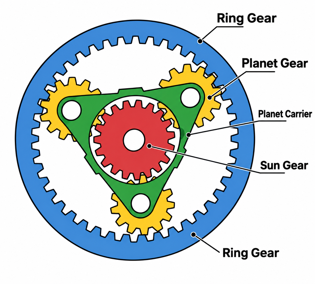
A planetary reducer generally has the ring gear fixed, the sun gear as input, and the planet carrier as output. At this time, the motor's transmission ratio is maximum. Assume the transmission ratio is i. The transmission ratio i is only related to the number of teeth of the ring gear Zr and the number of teeth of the sun gear Zs. The expression for the transmission ratio is:
One rotation of the sun gear pushes the planet gears to rotate on their own axes. But because the ring gear is fixed, the planet gears cannot simply rotate about a fixed axis; instead, they drive the planet carrier to rotate slowly. At this time, the motor rotor rotates i times, and the planet carrier rotates approximately 1 time.
The speed of the output planet carrier is reduced by a factor of i, but the output torque is increased by a factor of i. Therefore, the planetary reducer converts the motor's high speed and small torque into the low speed and large torque required by the joint.
4.4.2 DM Solution: Planetary Gear Joint Motor
The reBot DM version uses Damiao Technology's planetary gear joint motors, for example:
- DM4310: Reduction ratio approximately 10:1
- DM4340P: Reduction ratio approximately 40:1
The P version in DM4340P adopts a crossed roller bearing structure, used to withstand radial and axial loads generated during joint operation.
Its basic structure can be understood as:
High-speed motor → Planetary reducer → Joint output shaft
The motor itself has a relatively high rotational speed but limited output torque. After passing through the planetary reducer, the output speed decreases while the output torque is amplified.
Ideally, when the reduction ratio is (N:1):
Where:
N: reduction ratioω_motor: rotational speedT: torqueη: reducer transmission efficiency
Under the same other conditions, a 40:1 reducer can provide greater torque amplification capability compared to a 10:1 reducer, but at the same time the output speed will be further reduced.
Therefore, the core idea of the DM solution can be summarized as:
"The motor is responsible for high-speed rotation, and the reducer is responsible for amplifying torque."
Main advantages of the DM solution:
- Large output torque
- Relatively low motor load
- Suitable for joints requiring large static load capacity
- Heavy-load robotic arms
- Scenarios requiring large joint torque
- Scenarios where the requirement for absolute joint output speed is not particularly high
Main disadvantages of the DM solution:
- Poor backdrivability
The larger the reduction ratio, the more "difficult to push" the robotic arm usually is.
- High mechanical impedance
- Output speed is limited
4.4.3 RS Solution: QDD Quasi-Direct-Drive Joint Motor
The reBot RS version adopts Lingzu Era's QDD (Quasi-Direct Drive) joint motor. The core idea of QDD is exactly the opposite of traditional high-reduction-ratio joints:
Minimize the reduction ratio, allowing the motor to directly undertake more of the joint output task.
Its basic structure can be understood as: High-torque-density motor → Low-reduction-ratio planetary reducer → Joint output shaft. Therefore, QDD is not completely without a reducer, but rather:
"The reducer only provides a small amount of torque amplification, mainly relying on the motor's own high torque density to obtain joint output torque."
Why does QDD require a stronger motor? This is the key to understanding the difference between the two solutions. Assume both joints ultimately need to output:
If a 40:1 reducer is used, then theoretically the motor only needs to provide:
If an 8:1 reducer is used, then it needs:
That is to say: After the reduction ratio is lowered, the motor must provide more torque itself. Therefore, the QDD solution places higher demands on the motor, requiring the motor to have:
- Higher torque density
- Larger effective diameter
- Stronger heat dissipation capability
- Higher peak current withstand capability
- Better overload capability
This is also why QDD usually adopts solutions such as high-torque-density outer rotor motors. Related reviews also point out that QDD obtains better backdrivability and force transparency by reducing the reduction ratio, but at the cost of placing higher demands on motor torque density.
The greatest value of QDD is not simply "a smaller reduction ratio," but rather: making the joint closer to the dynamic characteristics of the motor itself. Due to the low reduction ratio, the influence of the reducer on system motion is relatively small, so the joint has better backdrivability.
4.4.4 Core Differences Between the Two Solutions
The two solutions can be understood as two completely different design philosophies.
| Comparison Item | DM Planetary Gear Drive | RS QDD (Quasi-Direct Drive) |
|---|---|---|
| Core Concept | Amplifies torque through a gearbox | Relies on a high-torque-density motor for output |
| Typical Gear Ratio | 10:1, 40:1 | Typically around 7.75:1–10:1 |
| Motor Torque Requirement | Relatively low | Higher |
| Output Torque | High | High, but more dependent on the motor itself |
| Output Speed | Relatively low | Relatively high |
| Backdrivability | Lower | Higher |
| Mechanical Impedance | Higher | Lower |
| Force Transparency | Lower | Higher |
| Compliant Control | Relatively difficult | More advantageous |
| Impact Resistance | Depends on the gearbox structure | Lower gear ratios are generally more favorable for impact resistance |
| Position Holding | Stronger | Relies more on active motor control |
| Motor Requirements | Relatively low | High torque density and high peak current capability |
| Typical Advantages | High torque and payload capacity | Dynamic response, backdrivability, and force control |
| Thermal Rise | Slower | Faster |
The high force transparency, strong backdrivability, and low mechanical impedance brought by QDD's low reduction ratio are its core advantages over high-reduction-ratio transmission solutions; at the same time, a low reduction ratio also means the motor needs to bear greater torque, therefore placing higher demands on the motor's torque density and thermal management.
- The DM planetary gear solution "trades a mechanical reducer for greater output torque".
- The QDD quasi-direct-drive solution "trades a higher-performance motor for better dynamic performance and force control capability".
There is no absolute sense of "which is more advanced" between the two. For a robotic arm, the real choice depends on the application goal:
- If load capacity, joint rigidity, and large torque output are more important → the DM solution has more advantages.
- If motion speed, backdrivability, human-robot collaboration, and force control are more important → the QDD solution has more advantages.
And for robotic arms oriented toward human-robot interaction, imitation learning, and reinforcement learning, QDD's low mechanical impedance and high backdrivability are particularly attractive, because the dynamic characteristics of the robotic arm are closer to the state of "the motor directly driving the load," which is conducive to high-dynamic motion and force interaction control.
4.5 Encoder
4.5 Encoder
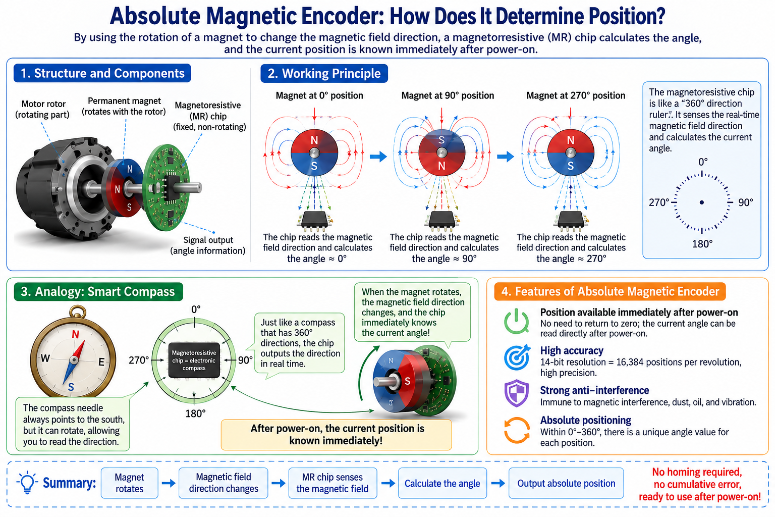
An encoder is used to measure rotation angle. Common types include incremental encoders, multi-turn absolute position encoders, and single-turn absolute position encoders. Both Damiao (DM) motors and Lingzu (RS) motors contain 2 single-turn absolute position magnetic encoders. The encoder resolution is 14 bits for both.
How an absolute position magnetic encoder determines position
An absolute position magnetic encoder uses a rotating magnet to change the magnetic field direction, and calculates the angle through a magnetoresistive chip, directly knowing the current position upon power-up.
Imagine the magnetic encoder as a smart compass with its own "map."
- The magnet is a small rotating magnet fixed on the motor rotor. When it rotates, the direction of the surrounding magnetic field changes accordingly — just like a compass needle always points south, but this needle can spin around.
- The magnetoresistive chip is the "map sensor." It has 360° direction markings around it, and it can read in real time, like reading a compass, whether the current magnetic field points to 0°, 90°, or 270°.
Why joint motors use two encoders
A joint motor contains 2 absolute position magnetic encoders, one measuring the high-speed motor rotor and one measuring the robot joint output shaft, used to compensate for reducer errors, improve accuracy, and ensure safety.
You are sitting in a car, holding the steering wheel (motor rotor end), but the steering wheel is not directly connected to the wheels; instead, it is connected to the wheels (motor output end) through a long, elastic spring flexible shaft (reducer).
If the steering wheel turns 10 times but the wheels only turn 9.8 times, the system immediately knows that 0.2 turns were absorbed by the spring flexible shaft, and immediately compensates a bit more — this compensates for the error with extremely high precision.
Position is not lost after power-off
The motor does not lose position after power-off because the absolute encoder saves the current position. Upon re-powering, it reads the angles on the motor side and output side, then recovers the position through reduction ratio verification.
4.6 Motor Interface and Wiring
4.6 Motor Interface and Wiring
DM Motor Interface and Wiring
| Name | Image | Function |
|---|---|---|
| XT30 (2+2) | 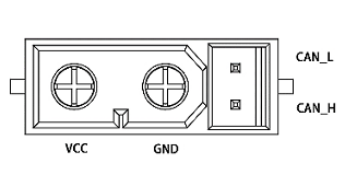 | 1. Connect the power supply through the XT30(2+2)-F plug power cable, with a rated voltage of 24V, to power the motor. 2. Connect external control devices through the CAN communication terminal, which can receive CAN control commands and feed back motor status information. 3. The motor contains two power interfaces, either interface (including the CAN communication terminal) can be used independently, or multiple motors can be connected in series for convenient wiring. |
| GH1.25 3-pin | 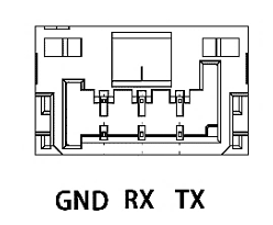 | Through the GH1.25 cable-3pin, use a USB2CAN debugging tool to connect to a PC, and use the Damiao Technology debugging assistant to perform parameter settings and firmware upgrades on the motor. |
RS Motor Interface and Wiring
| Name | Image | Function |
|---|---|---|
| XT30 (2+2) | 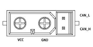 | 1. Connect the power supply through the XT30(2+2)-F plug power cable, with a rated voltage of 24V, to power the motor. 2. Connect external control devices through the CAN communication terminal, which can receive CAN control commands and feed back motor status information. 3. The motor contains two power interfaces, either interface (including the CAN communication terminal) can be used independently, or multiple motors can be connected in series for convenient wiring. |
4.7 DM Motor Control Modes
4.7 DM Motor Control Modes
The electronic speed controller converts the received CAN data into control variables for calculation, obtaining a torque value as the current reference for the current loop. The current loop ultimately reaches the given torque current according to its adjustment law.
MIT Protocol
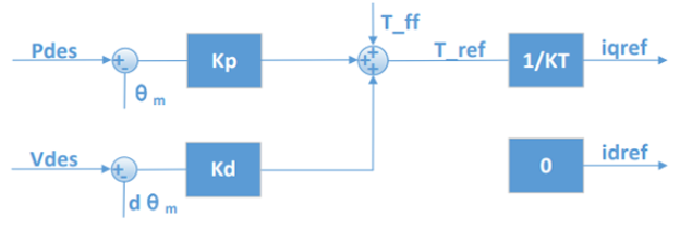
MIT mode can control the motor through three parameters: position, velocity, and torque.
The final output torque of the motor is mainly determined jointly by the following parameters:
- Pdes: Target position
- Vdes: Target velocity
- Kp: Position control strength; the larger Kp is, the more the motor tends to quickly return to the target position
- Kd: Velocity control strength; can be used to suppress motor vibration and make motion more stable
- T_ff: Directly given torque
It can be simply understood as:
Motor output = Position control + Velocity control + Feedforward torque
MIT mode can achieve different control methods according to different parameter combinations:
Position control
- Set Pdes, Kp, Kd.
- The motor will move to the specified position and suppress vibration during motion through Kd.
Velocity control
- Set Kp = 0, Kd ≠ 0
- Then give Vdes to control the motor to rotate at the target velocity.
Torque control
- Set Kp = 0, Kd = 0
- Then directly set T_ff to control the motor to output the specified torque.
When controlling position, kd cannot be set to 0, otherwise it will cause motor oscillation or even loss of control.
Position-Velocity Mode
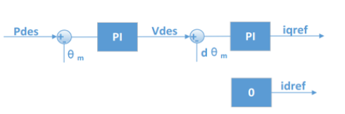
The position cascade mode adopts a three-loop cascade control mode, with the position loop as the outermost loop, its output as the reference for the velocity loop, and the output of the velocity loop as the reference for the inner current loop, used to control the actual current output.
The final output torque of the motor is mainly determined jointly by the following parameters:
- p_des: The target position for control.
- v_des: Used to limit the maximum absolute velocity during motion.
- kp_pos: Determines the amplification factor of position error on velocity command.
- ki_pos: Determines the static position holding force.
- kp_vel: Directly determines the dynamic acceleration torque.
- ki_vel: Determines the anti-load-disturbance capability during the constant velocity segment.
If the position cascade mode uses the control parameters recommended by the debugging assistant, it can achieve good control accuracy, and the control process is relatively compliant, but the response time is relatively long. In addition to v_des, configurable related parameters also include acceleration/deceleration settings. If additional oscillation occurs during the control process, the acceleration/deceleration can be increased.
The units of p_des and v_des are rad and rad/s respectively, the data type is float, and the damping factor must be set to a non-zero positive number.
Velocity Mode
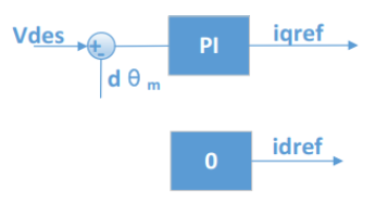
The outer loop of velocity mode is the velocity loop, and the output of the velocity loop serves as the reference for the inner current loop.
The final output torque of the motor is mainly determined jointly by the following parameters:
- v_des: Target velocity during motion.
- kp_vel: Directly determines the dynamic acceleration torque.
- ki_vel: Determines the anti-load-disturbance capability during the constant velocity segment.
The unit of v_des is rad/s, and the data type is float. If you need to use the debugging assistant to automatically calculate parameters, you need to set the damping factor to a non-zero positive number, usually ranging from 2.0 to 10.0. A damping factor that is too small will bring velocity oscillation and large overshoot, while a damping factor that is too large will bring a long rise time. The recommended setting value is 4.0.
PVT Mode (Force-Position Hybrid Control)
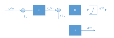
PVT (force-position hybrid control) mode dynamically controls the magnitude of output torque based on position-velocity mode control. A current command saturation link is added after the output command of the velocity loop, so that the reference of the current loop is limited within a given range.
The final output torque of the motor is mainly determined jointly by the following parameters:
- p_des: The target position for control.
- v_des: Used to limit the maximum absolute velocity during motion.
- kp_pos: Determines the amplification factor of position error on velocity command.
- ki_pos: Determines the static position holding force.
- kp_vel: Directly determines the dynamic acceleration torque.
- ki_vel: Determines the anti-load-disturbance capability during the constant velocity segment.
4.8 Different Modes of RS Motors
4.8 Different Modes of RS Motors
Motion Control Mode
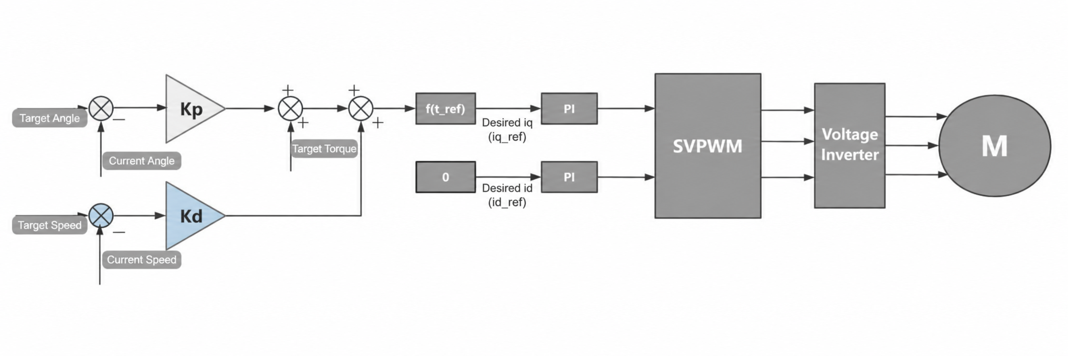
The motion control mode of RS is similar to the MIT mode of DM. The control logic of motion control mode is as follows:
Finally, t_ref is converted to the desired iq current through an internal formula and output through the current loop.
The final output torque of the motor is mainly determined jointly by the following parameters:
- Pdes: Target position
- Vdes: Target velocity
- Kp: Position control strength; the larger Kp is, the more the motor tends to quickly return to the target position
- Kd: Velocity control strength; can be used to suppress motor vibration and make motion more stable
- T_ff: Directly given torque
It can be simply understood as:
Motor output = Position control + Velocity control + Feedforward torque
Motion control mode can achieve different control methods according to different parameter combinations:
Position control
- Set Pdes, Kp, Kd.
- The motor will move to the specified position and suppress vibration during motion through Kd.
Velocity control
- Set Kp = 0, Kd ≠ 0
- Then give Vdes to control the motor to rotate at the target velocity.
Torque control
- Set Kp = 0, Kd = 0
- Then directly set T_ff to control the motor to output the specified torque.
Current Mode
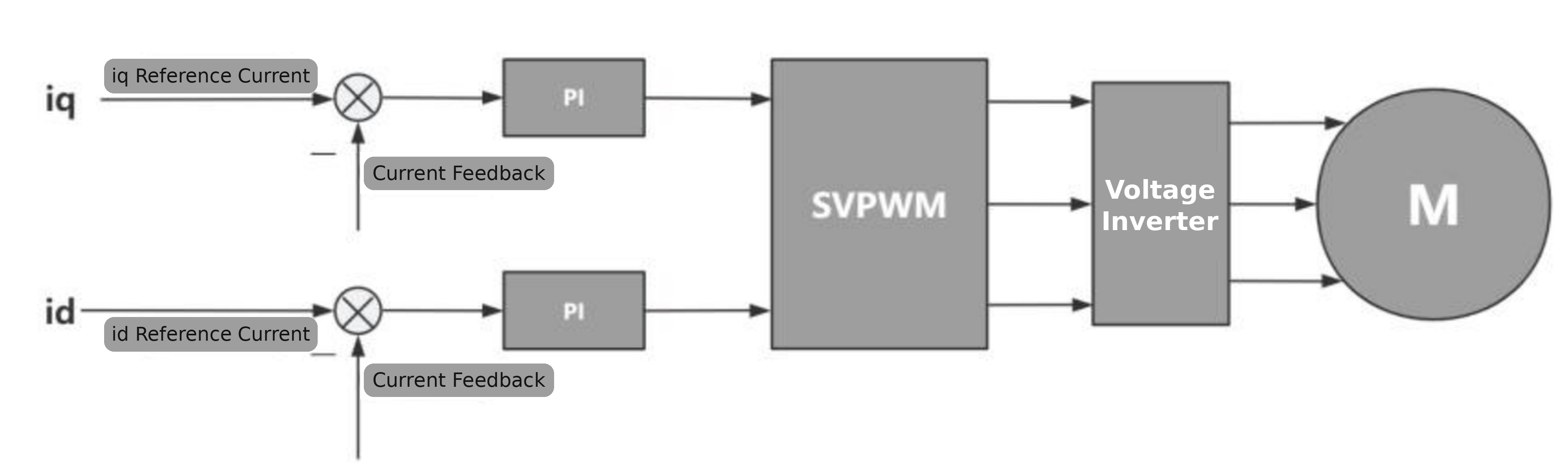
This provides the motor's current loop as a control interface to the user. This mode is generally not used. The usage of this interface can refer to the FOC algorithm.
Velocity Mode
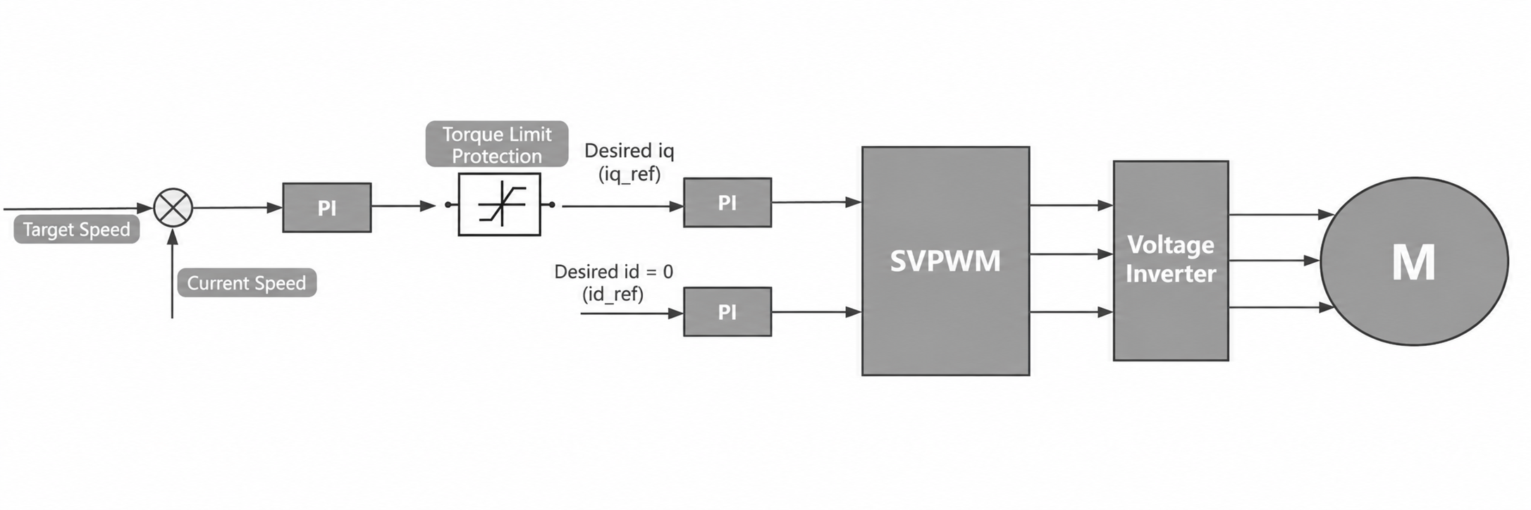
Velocity mode uses the difference between the set velocity and the current velocity as the input to the PI controller, and the output torque of the PI controller is limited to a range. The torque is converted to the desired iq current through an internal formula and output through the current loop.
The final output torque of the motor is mainly determined jointly by the following parameters:
- v_des: Target velocity during motion, that is, the current velocity.
- kp_vel: Directly determines the dynamic acceleration torque.
- ki_vel: Determines the anti-load-disturbance capability during the constant velocity segment.
- Torque protection: Limits the output torque.
Position-Velocity Mode (CSP)
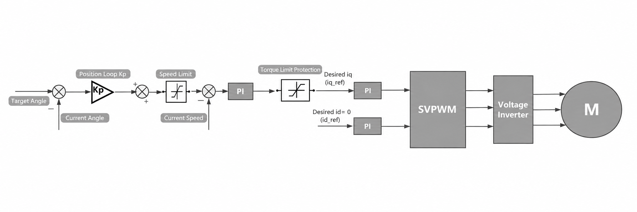
Position mode CSP can also be called position-velocity mode. The difference between the set angle and the current angle is used as the input to the position loop, where the position loop is a pure proportional controller. The output of the position loop passes through velocity limiting and then serves as the input to the velocity loop. The velocity loop is a PI controller, and the output torque passes through torque protection limiting and is then converted to the desired iq current, output through the current loop.
The final output torque of the motor is mainly determined jointly by the following parameters:
- p_des: The target position for control.
- v_des: Used to limit the maximum absolute velocity during motion.
- kp_pos: Determines the amplification factor of position error on velocity command.
- ki_pos: Determines the static position holding force.
- kp_vel: Directly determines the dynamic acceleration torque.
- ki_vel: Determines the anti-load-disturbance capability during the constant velocity segment.
- Torque protection: Limits the desired output torque.
Position-Velocity Mode (PP)
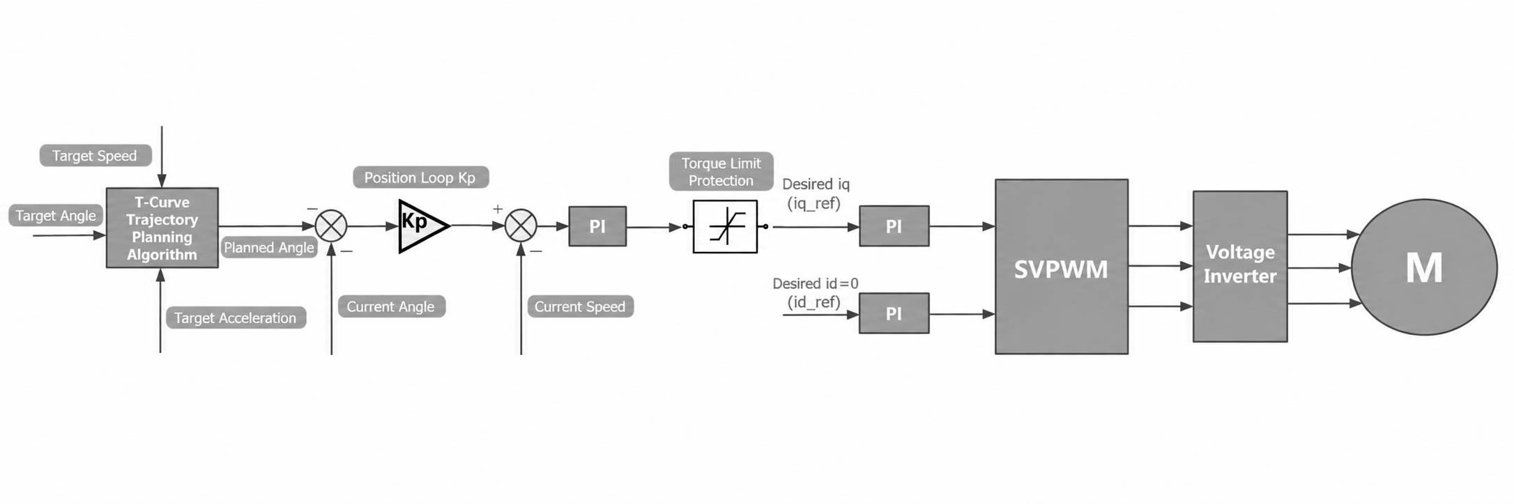
This mode is also the position-velocity mode interface provided by motorbridge.
Position mode PP adds a trapezoidal velocity curve planning compared to CSP. It inputs the set velocity, set angle, and set acceleration, and outputs the planned angle. The planned angle output by the t-curve planner serves as the input to the position loop, where the position loop is a pure proportional controller. The output of the position loop passes through velocity limiting and then serves as the input to the velocity loop. The velocity loop is a PI controller, and the output torque passes through torque protection limiting and is then converted to the desired iq current, output through the current loop.
The final output torque of the motor is mainly determined jointly by the following parameters:
t-curve planner parameters:
- p_set: The set desired target position.
- v_des: The set desired velocity value.
- Acc_set: The set desired acceleration.
Position loop / velocity loop parameters:
- p_des: The target position for control.
- v_des: Used to limit the maximum absolute velocity during motion.
- kp_pos: Determines the amplification factor of position error on velocity command.
- ki_pos: Determines the static position holding force.
- kp_vel: Directly determines the dynamic acceleration torque.
- ki_vel: Determines the anti-load-disturbance capability during the constant velocity segment.
- Torque protection: Limits the desired output torque.
4.9 Emergency Stop and Abnormal Power-Off Principles
4.9 Emergency Stop and Abnormal Power-Off Principles
-
Abnormal shaking must be immediately powered off. High-frequency shaking means the motor is outputting high-frequency forward and reverse torques, and if the power is not immediately cut off, it may lead to motor damage.
-
Hitting a limit must be immediately powered off. Hitting a limit means the motor may be stalling. If the power is not immediately cut off, it may lead to motor overheating or damage.
-
Abnormal situations such as sudden falling of the robotic arm must be immediately powered off to prevent other unexpected situations.