5. CAN Bus and Motor Communication
Chapter 5 of the Seeed Embodied Intelligence Beginner's Course — CAN bus basics, standard vs extended data frames, the CAN data link layer, and SocketCAN.
After completing this section, you should be able to understand the following questions:
- How a piece of data is sent out on the CAN bus;
- What parts a CAN data frame consists of;
- What CAN ID, DLC, and Data respectively represent;
- What the difference is between standard frames and extended frames;
- What the roles of fields such as CRC and ACK are.
For practical development, it is not necessary to memorize every bit in a CAN frame from the start.
The most important thing at the beginner stage is to first understand: ID, DLC, Data.
5.1 CAN Basic Principles
5.1 CAN Basic Principles
CAN is the abbreviation for Controller Area Network, and is an ISO international standardized serial communication protocol. The CAN bus network structure has two forms: closed-loop and open-loop.
Generally, the CAN bus network structure used by robotic arms or robots uses a closed-loop CAN bus network, that is, a 120-ohm resistor is connected at each end of the bus, and the two signal lines form a loop. This CAN bus network is defined by the ISO 11898 standard and is a high-speed, short-distance CAN network with a communication rate of 125 kbit/s to 1 Mbit/s. At a communication rate of 1 Mbit/s, the maximum bus length is 40 m.
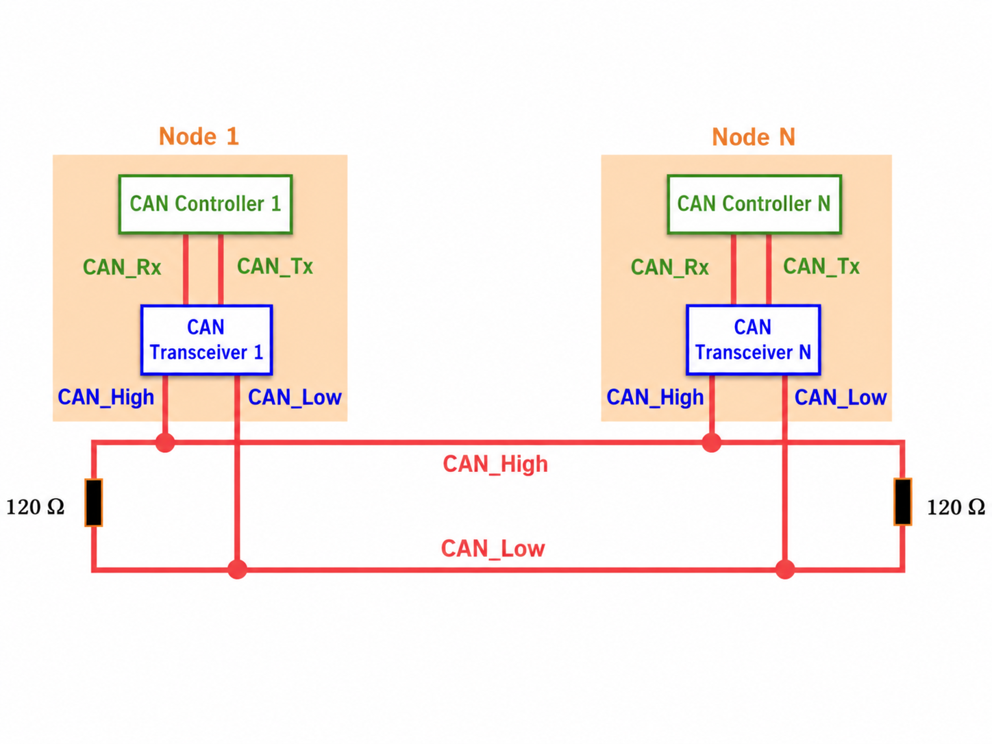
The bus consists of two signal lines, CAN_L and CAN_H. CAN transmits differential signals, representing the bus level through the voltage difference between the two signal lines, that is, CAN_H - CAN_L. The one corresponding to logic 1 is called the recessive level, and the one corresponding to logic 0 is called the dominant level. In ISO 11898, the recessive level is near a voltage difference of 0, and the dominant level is mainly near a voltage difference of 2V.
5.2 CAN Protocol
5.2 CAN Protocol
| Frame Type | Frame Purpose |
|---|---|
| Data Frame | Sends data |
| Remote Frame | Requests data |
| Error Frame | Reports bus errors |
| Overload Frame | Requests delay |
| Inter Frame Space | Separates consecutive frames |
Since DM motors use CAN 2.0 standard data frames and RS motors use CAN 2.0 extended data frame format, only these two data frame formats are introduced below. It is recommended to read the following introduction against the protocol section in the motor's data sheet.
5.2.1 reBot DM Standard Data Frame (11 bytes total)
| Byte | Field | Bit Assignment |
|---|---|---|
| Byte 1 | Frame Information | Bit 7: FF, Bit 6: RTR, Bit 5: X, Bit 4: X, Bits 3–0: DLC |
| Byte 2 | Frame ID 1 | Bits 7–0: ID10–ID3 |
| Byte 3 | Frame ID 2 | Bits 7–5: ID2–ID0, Bits 4–0: X |
| Byte 4 | Data 1 | DATA1 |
| Byte 5 | Data 2 | DATA2 |
| Byte 6 | Data 3 | DATA3 |
| Byte 7 | Data 4 | DATA4 |
| Byte 8 | Data 5 | DATA5 |
| Byte 9 | Data 6 | DATA6 |
| Byte 10 | Data 7 | DATA7 |
| Byte 11 | Data 8 | DATA8 |
Frame description part (first 3 bytes):
- Byte 1 is frame information. Bit 7 (FF) indicates the frame format. In a standard frame, FF is 0. Bit 6 (RTR) indicates the frame type. RTR=0 indicates a data frame, and RTR=1 indicates a remote frame. DLC indicates the actual data length when it is a data frame.
- Bytes 2 to 5 are the frame ID. The ID of a standard data frame has 11 bits. Sent sequentially from ID10 to ID0, there can be 211 types of messages. The frame ID range is: 000-7FF.
It is forbidden for the upper 7 bits to all be recessive (forbidden setting: ID=1111111XXXX).
Frame data part (last 8 bytes):
- Bytes 4~11 are the actual data of the data frame.
5.2.2 reBot RS Extended Data Frame (13 bytes)
| Byte | Field | Bit Assignment |
|---|---|---|
| Byte 1 | Frame Information | Bit 7: FF, Bit 6: RTR, Bit 5: X, Bit 4: X, Bits 3–0: DLC |
| Byte 2 | Frame ID 1 | Bits 7–0: ID28–ID21 |
| Byte 3 | Frame ID 2 | Bits 7–0: ID20–ID13 |
| Byte 4 | Frame ID 3 | Bits 7–0: ID12–ID5 |
| Byte 5 | Frame ID 4 | Bits 7–3: ID4–ID0, Bits 2–0: X |
| Byte 6 | Data 1 | DATA1 |
| Byte 7 | Data 2 | DATA2 |
| Byte 8 | Data 3 | DATA3 |
| Byte 9 | Data 4 | DATA4 |
| Byte 10 | Data 5 | DATA5 |
| Byte 11 | Data 6 | DATA6 |
| Byte 12 | Data 7 | DATA7 |
| Byte 13 | Data 8 | DATA8 |
Frame description part (first 5 bytes):
- Byte 1 is frame information. Bit 7 (FF) indicates the frame format. In an extended frame, FF is 1. Bit 6 (RTR) indicates the frame type. RTR=0 indicates a data frame, and RTR=1 indicates a remote frame. DLC indicates the actual data length when it is a data frame.
- Bytes 2 to 5 are the frame ID. The ID in extended format has 29 bits. The basic ID is from ID28 to ID18, and the extended ID is represented by ID17 to ID0. The basic ID is the same as the ID in standard format. There can be 229 types of messages, and there are gaps on the data link (transparent to the operator). The frame ID range is 0000 0000-1FFF FFFF.
It is forbidden for the upper 7 bits to all be recessive (forbidden setting: basic ID=1111111XXXX).
Frame data part (last 8 bytes):
- Bytes 6~13 are the actual data of the data frame.
5.2.3 CAN Data Link Layer
The CAN bus can be understood as a "group chat." Many devices are connected to the bus, for example:
- Main controller;
- Motors;
- Sensors;
- Battery management system;
- Other control modules.
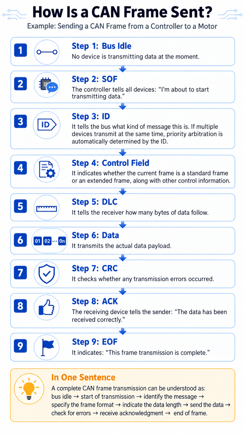
All devices share the same CAN bus. When a device wants to send data, it cannot just send it arbitrarily; instead, it must package the data into a complete CAN data frame according to the format specified by the CAN protocol.
A CAN frame can be simply understood as:
Start sending → Message number → Data length → Actual data → Data check → Receive confirmation → End sending
The corresponding CAN frame structure can be simplified as:
SOF → ID → Control field → DLC → Data → CRC → ACK → EOF
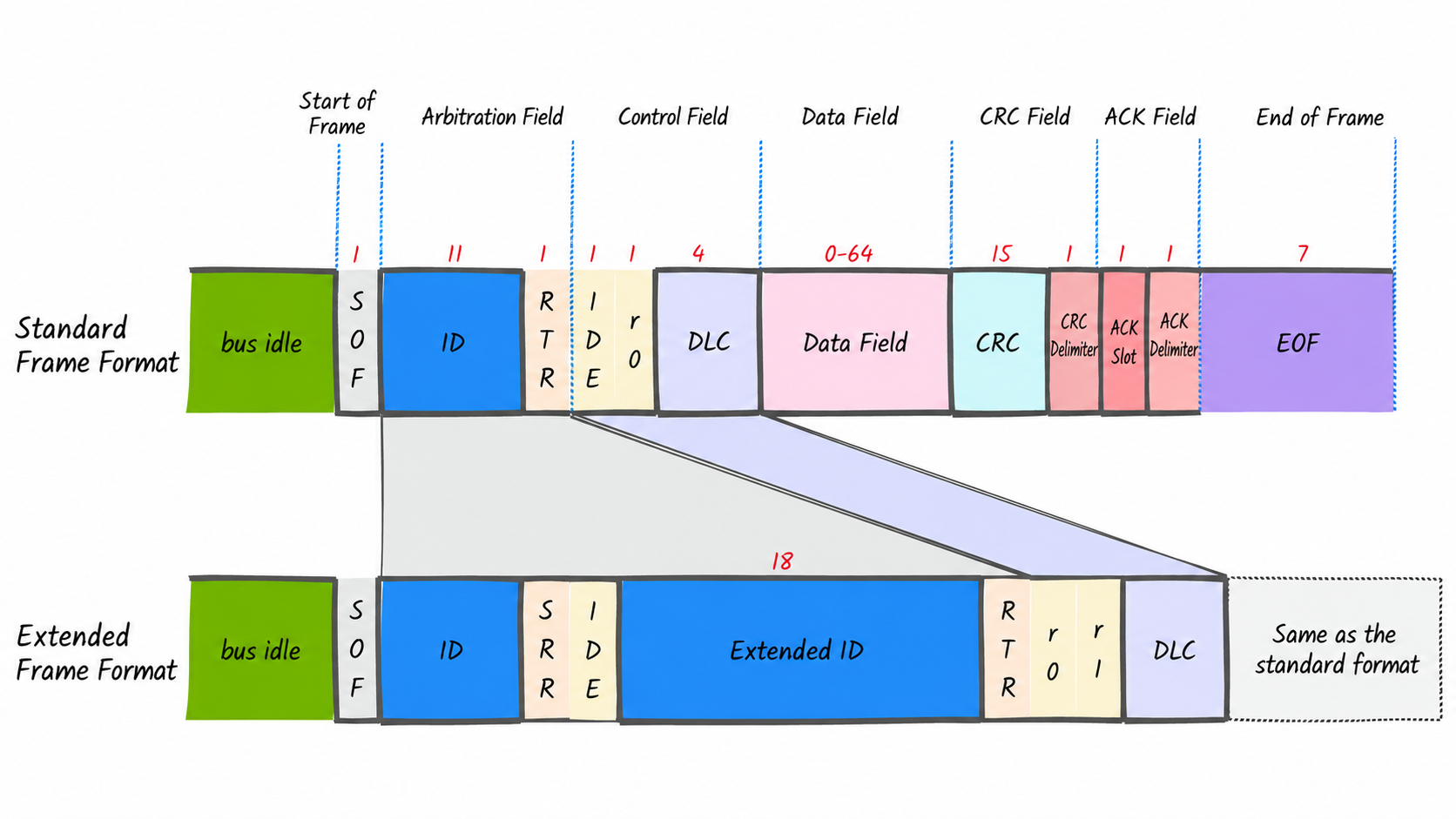
See the table below for a detailed explanation:
| Name | Function |
|---|---|
| Idle segment (bus idle) | The bus is at recessive level 1, and no node operates the bus. When no device is sending data, the CAN bus is in an idle state. Currently no device is speaking, and everyone is waiting. |
| Start of Frame (SOF) | SOF is fixed as one dominant bit 0. Since the CAN bus is 1 when idle, when 0 suddenly appears on the bus, other devices know: a device has started sending data. Therefore, SOF can be understood as: "I'm starting to send." |
| Arbitration segment (frame ID, RTR or SRR) | ID — it can be understood as the number of this message. For example, in motor control, 0x01 can be used: motor 1 control command; 0x02: motor 2 control command, etc. ID more accurately represents "the identity or type of the message." The smaller the ID value, the higher the priority. RTR — it is mainly used to distinguish: ordinary data frame RTR=0 and remote request frame RTR=1. When sending ordinary CAN data daily, RTR is generally 0. SRR — an arbitration bit dedicated to extended frames, fixed at 1. Mainly used to ensure that under the same basic ID, standard frames take priority over extended frames. |
| Control segment (IDE, reserved bits, DLC) | The IDE bit is used to distinguish standard frames from extended frames. IDE = 1 extended frame, 29-bit ID. IDE = 0 standard frame, 11-bit ID. The extended frame has a larger ID range and can provide more message numbers. DLC — tells the receiver how much data there is. For example: DLC = 1, indicating 1 Byte of data (8 bits); DLC = 4, indicating 4 Bytes of data (32 bits); DLC = 8, indicating 8 Bytes of data (64 bits). |
| Data Field | This is the actual data content, with a length corresponding to DLC. For example, the main controller needs to send to the motor: target position; target velocity; target torque. Check the CAN communication protocol provided by the device manufacturer to confirm what each byte represents. |
| CRC segment | The "check code" of CAN data. Performs CRC calculation on all data bits, including frame start, arbitration segment, control segment, and data segment. Checks whether errors occur during CAN data transmission. The CRC delimiter must be at recessive level. |
| ACK segment | ACK — tells the sender "I received it." After the sender finishes sending, it releases the bus to recessive level 1. If the receiver receives correctly, it needs to reply with dominant level 0 at this bit. At this time, the sender reads the ACK slot as 0, indicating that ACK was received. The ACK delimiter is when the receiver releases the level, which is recessive. |
| End of Frame (EOF, End Of Frame) | The current CAN data transmission ends. 7 recessive 1s. |
5.3 SocketCAN
5.3 SocketCAN
SocketCAN is a mainstream implementation of the CAN protocol on Linux systems. SocketCAN uses the socket API and Linux network stack technology to implement CAN device drivers as network interfaces, making it easy to use and highly compatible.
Reference documentation for detailed usage: https://docs.linuxkernel.org.cn/networking/can.html