6.1 Robotic Arm Assembly
6.1 Robotic Arm Assembly
reBot DM Robotic Arm Assembly
reBot RS Robotic Arm Assembly
6.2 Power Supply Assembly
6.2 Power Supply Assembly
reBot DM Power Supply Assembly
reBot RS Power Supply Assembly
6.3 Robotic Arm Wiring
6.3 Robotic Arm Wiring
reBot DM Wiring
Connect the robotic arm to the adapter board.
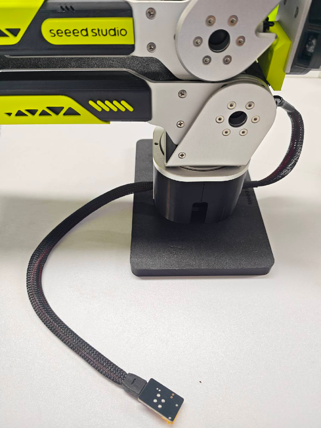
Power supply connection: XT60 to XT30 cable.
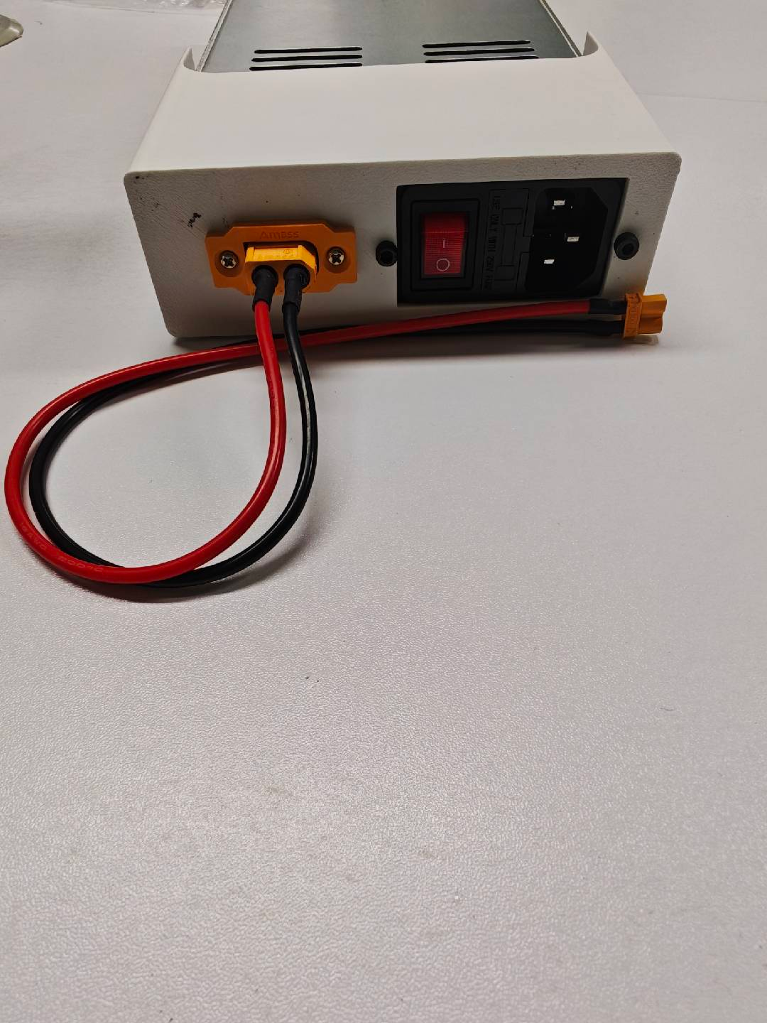
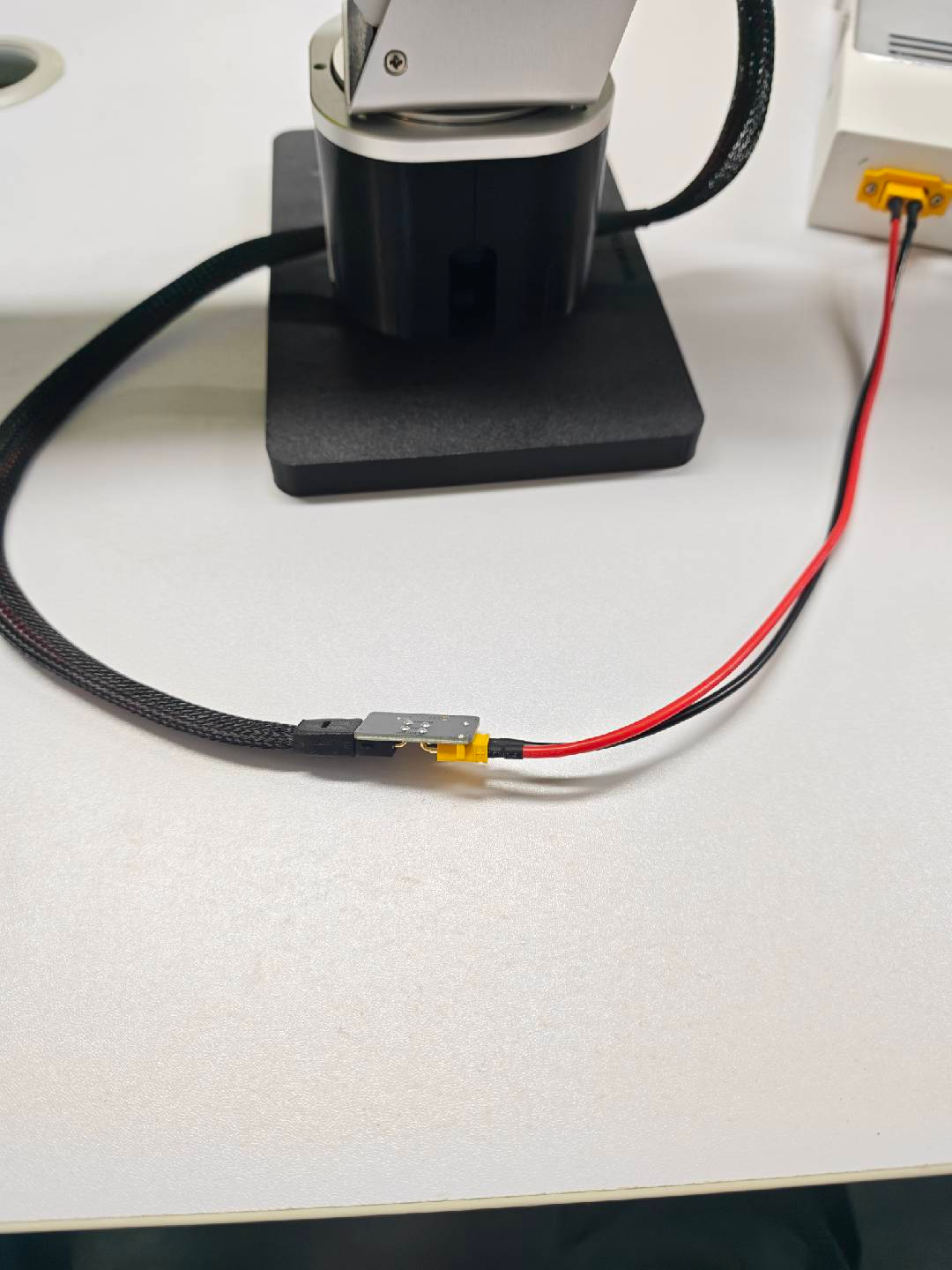
Connect the XT60 to XT30 cable to the adapter board.
Connect USB2CAN to GH1.25 2-pin.
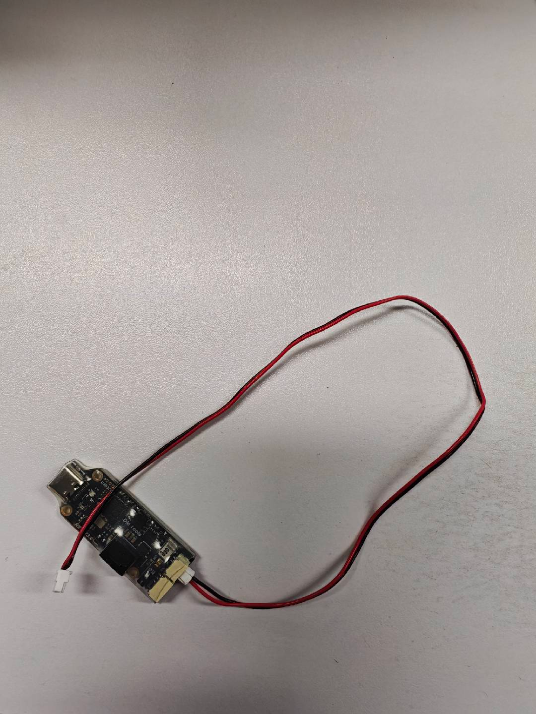
Connect the other end of the GH1.25 2-pin cable to the adapter board.
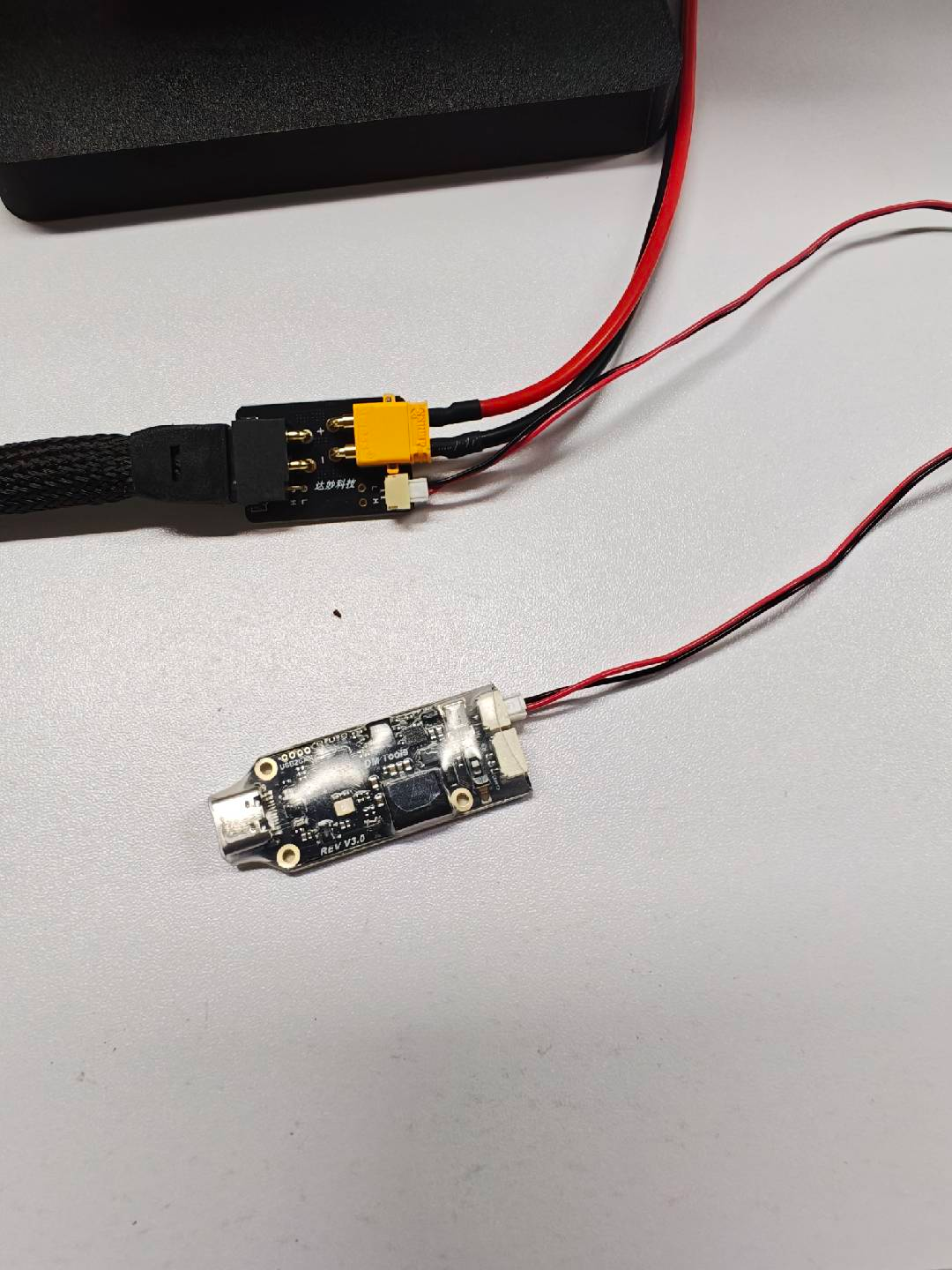
Connect USB2CAN to the computer via a Type-C data cable.
Motor 1 and motor 2 must be connected to each other.
reBot RS Wiring
Connect the robotic arm to the adapter board.
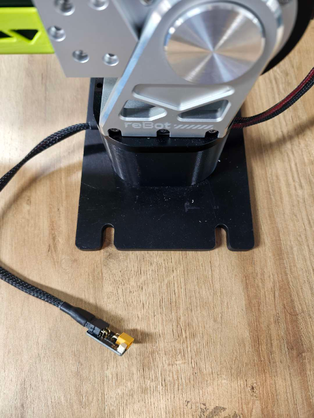
Power supply connection: XT60 to XT30 cable.
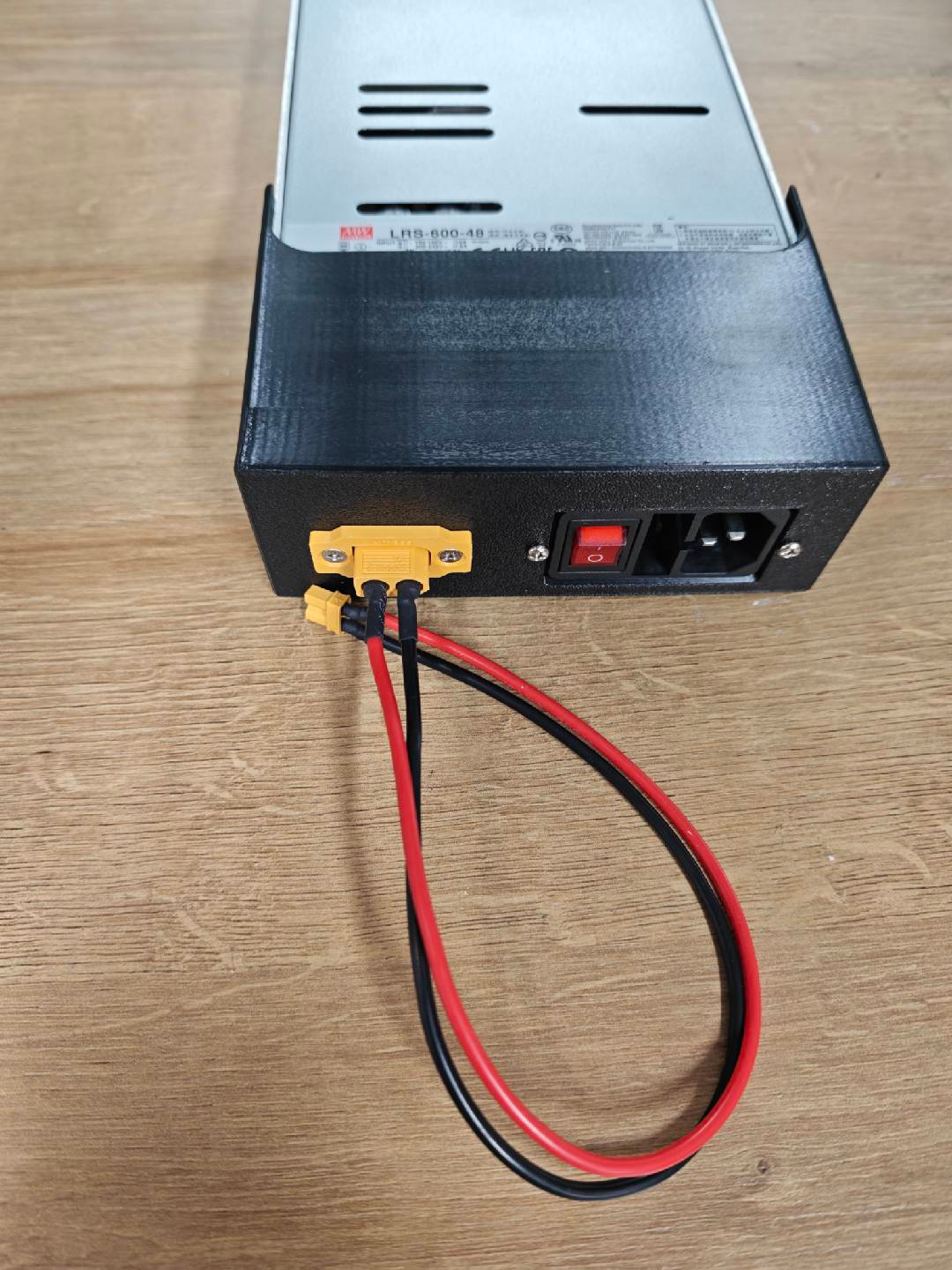
Connect the XT60 to XT30 cable to the adapter board.
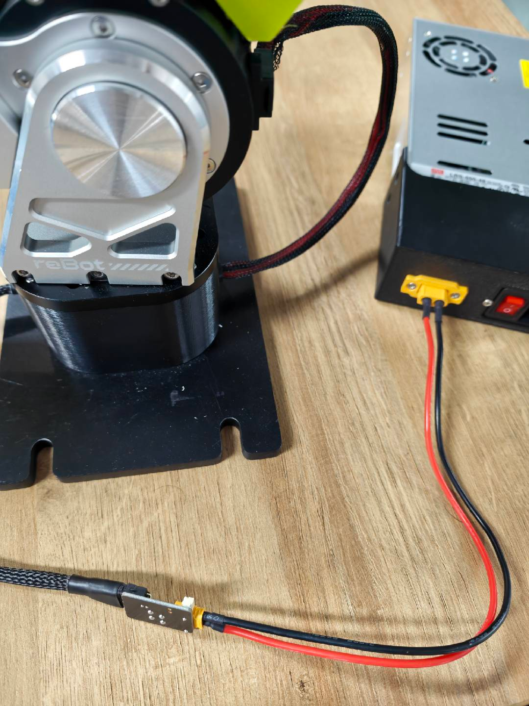
Connect CANable to GH1.25 2-pin cable.
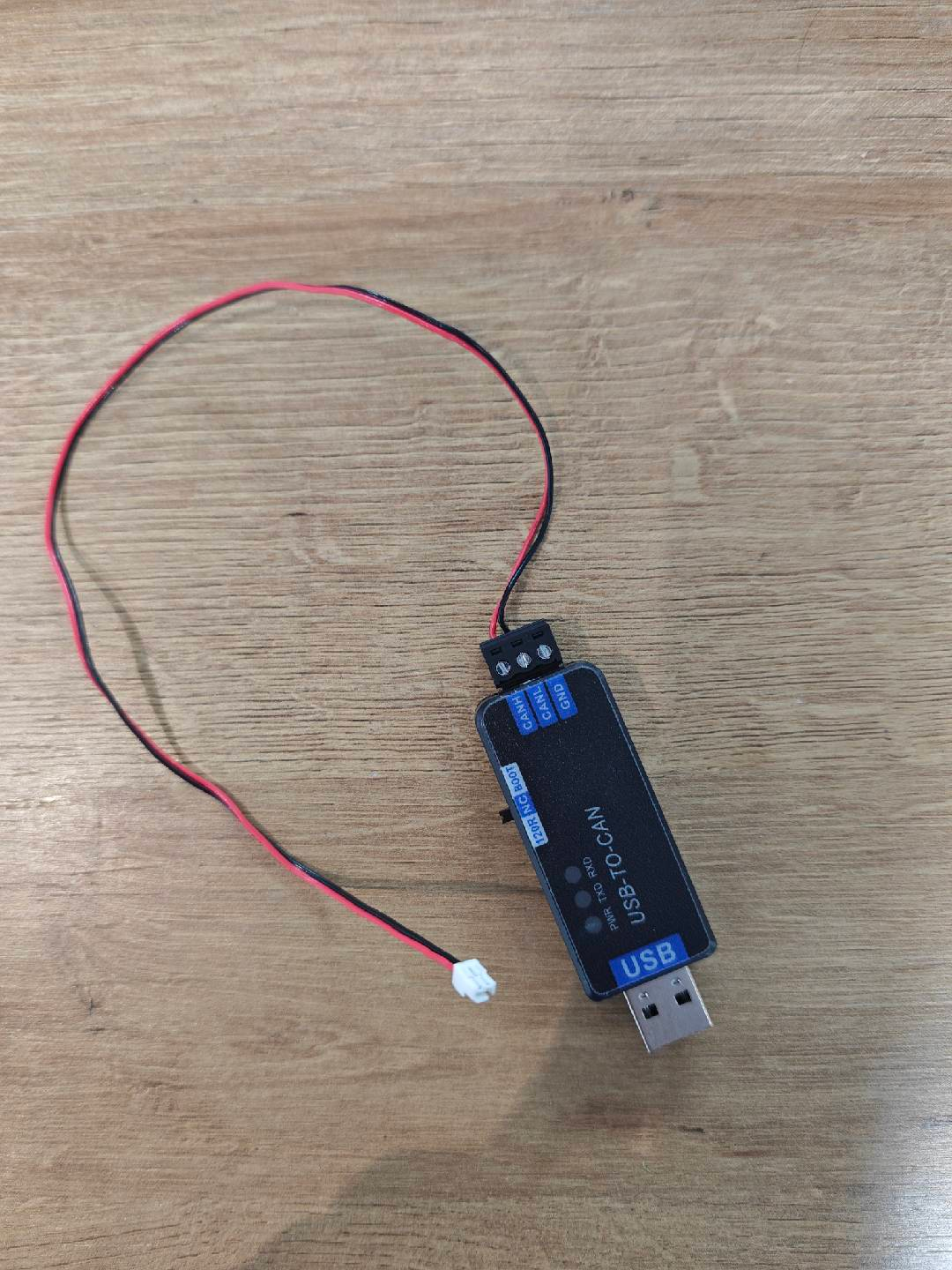
Connect the other end of the GH1.25 2-pin cable to the adapter board.
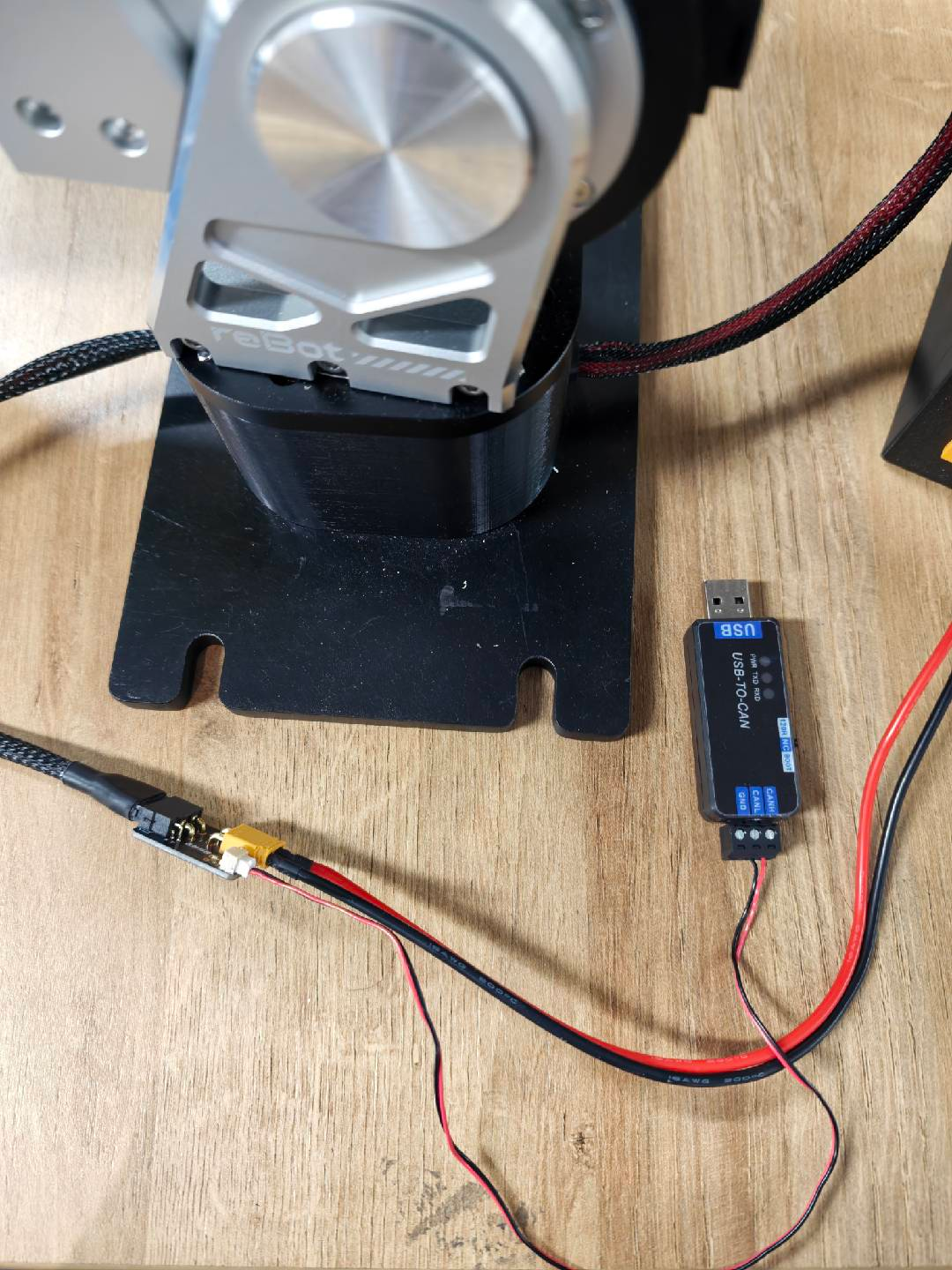
Connect CANable to the computer.
Motor 1 and motor 2 must be connected to each other.
6.4 Robotic Arm Power Supply Requirements
6.4 Robotic Arm Power Supply Requirements
The power supply requirement for reBot DM is 24V, and the power supply requirement for reBot RS is 48V.
Below are our recommended power supply usage instructions:
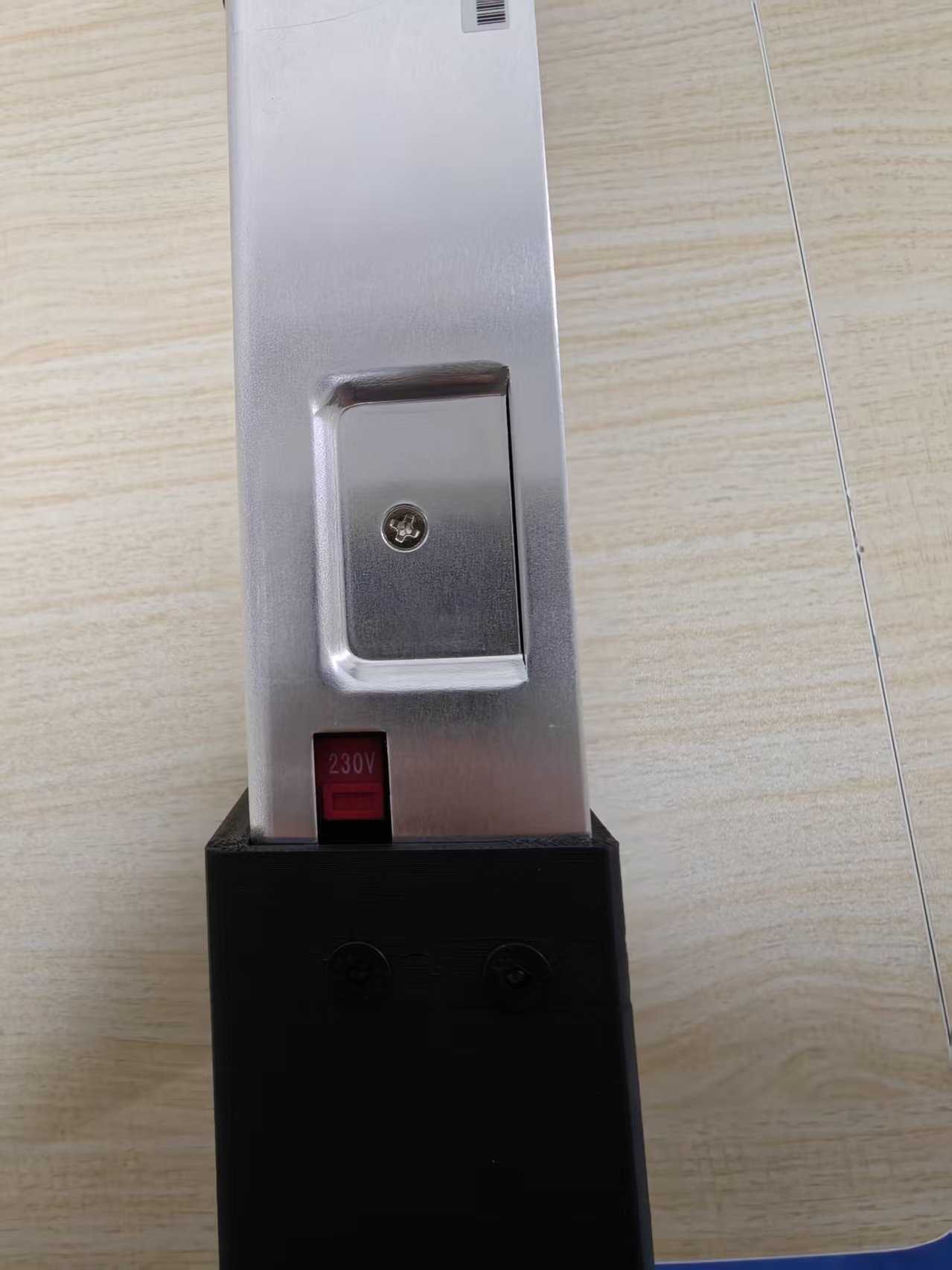
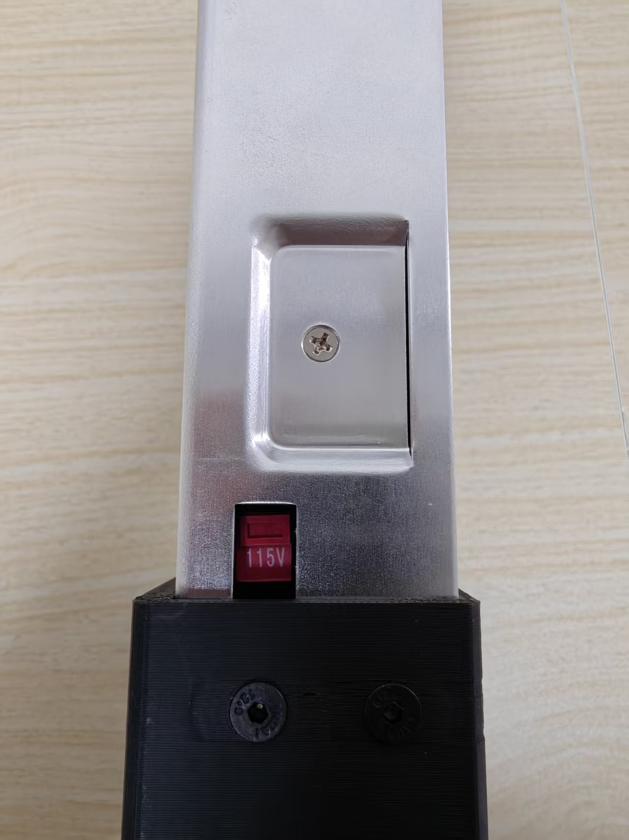
If your household voltage is 220V, please set the DIP switch on the side of the power supply to 230V. If your household voltage is 110V, please set the DIP switch on your power supply to 115V.
| 220V → 230V | 110V → 115V |
|---|---|
 |  |
6.5 Robotic Arm Power-On
6.5 Robotic Arm Power-On
For the reBot DM robotic arm, the lights of all joints will light up and turn red, at which point the robotic arm is in a disabled state.
The reBot RS robotic arm is no different from when it is powered off, and can only be determined through communication with the motor.