Getting Started with reCamera Gimbal
Introduction
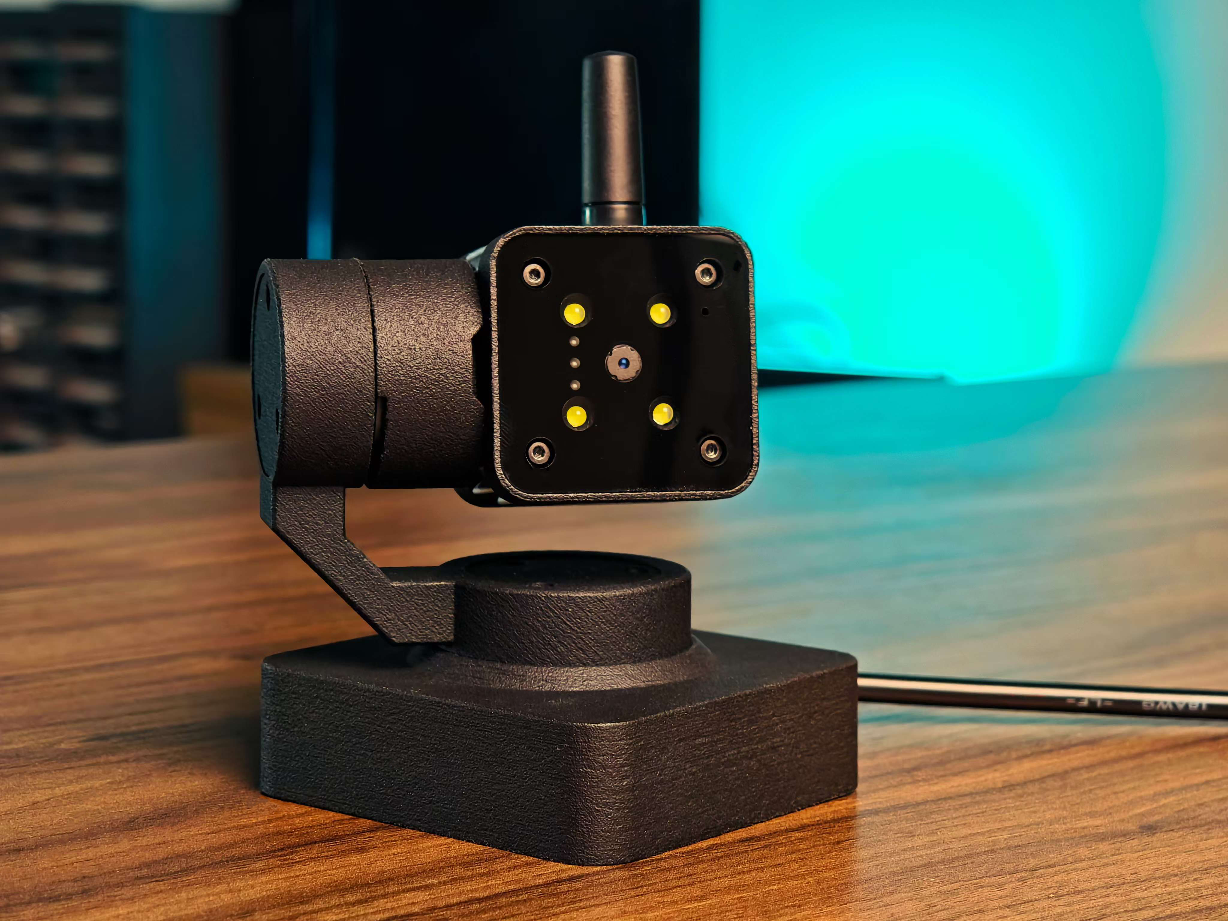
Welcome to reCamera Gimbal! The reCamera gimbal 2002 series is the first open-source camera control system, composed of one tiny AI camera - reCamera 2002w 8GB/64GB, and one compatible 2-Axis gimbal basement with 2 brushless motors. It is powered by an RISC-V SoC, providing 1 TOPS AI performance with video encoding at 5MP @ 30 FPS. It offers a Lego-like self-assembly package and integrates the Sensecraft AI platform and Node-RED platform for smooth graphical programming and pipeline construction, enabling rapid self-training, model conversion, and deployment of AI models such as Yolo v5/v8/11.
This guide will help you quickly set up your device and start using it to unlock powerful AI-Vision features. Whether you're a beginner or an experienced user, this step-by-step walkthrough will guide you through the installation, configuration, and first use.
Prerequisites
- reCamera Gimbal
- User manual (inside the box)
- 12V DC power adapter to 5521 DC Plug (Purchase link)
- USB Type C (Purchase lini)
- Wi-Fi Connection
- Eletrical screw driver (Optional for better assembling experience)
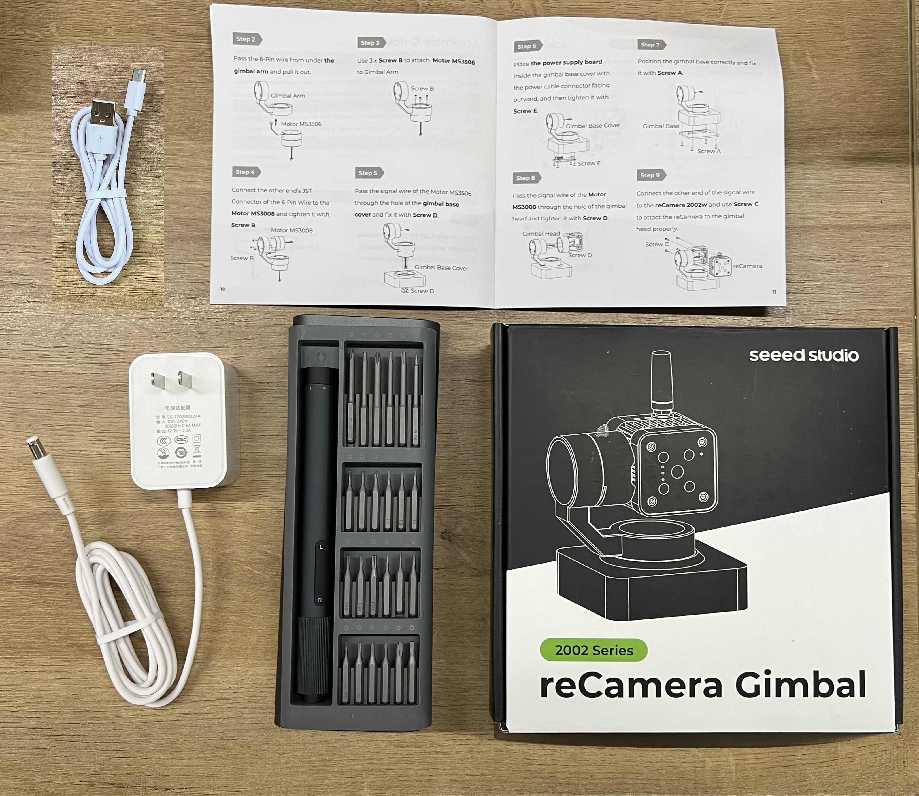
Unboxing
Start by unpacking your reCamera Gimbal. Inside the box, you should find:
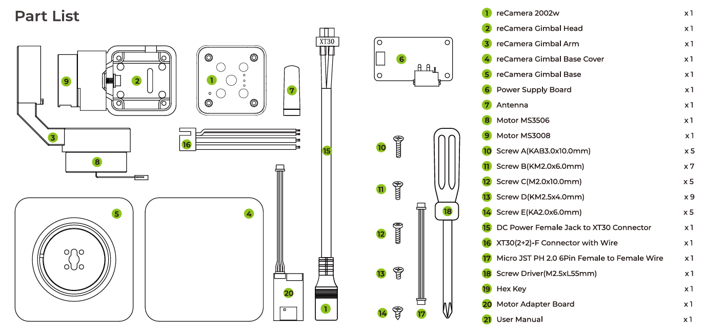
Make sure all parts are included.
Hardware Assembly
Assemble the reCamea Gimbal according to the assembly instructions on Box or User manual.
Please make sure all screws are tightened, otherwise it will affect the operation of the motor.
Setup device and login
Step1: After assembling the Gimbal, connect the usb cable from reCamera Gimbal to your PC. Navigate to 192.168.42.1 on website and change the default password. If you are using the WiFi AP setup mode, navigate instead to 192.168.16.1
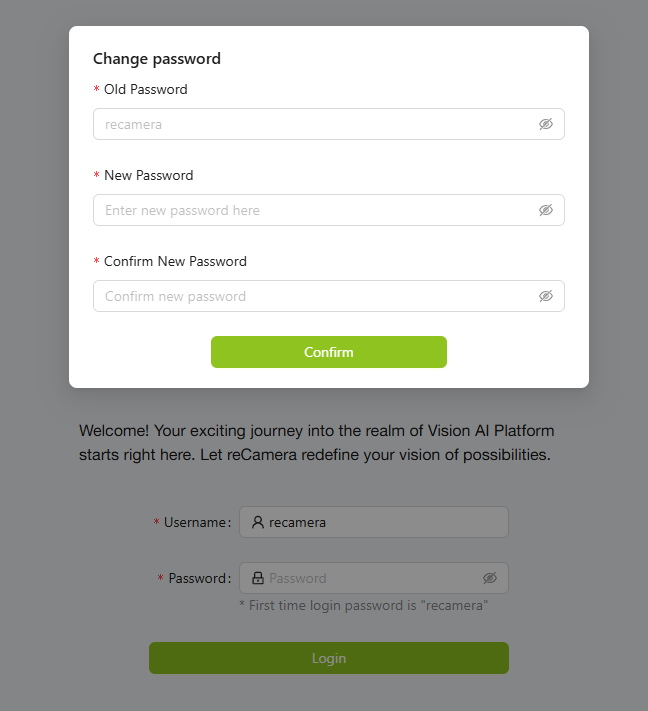
Please remember your password, otherwise all logs will be erased to reset your device. If you forget the password, please factory reset your device.
The default username and password are both recamera. If you perform a factory reset or are using a new (unconfigured) device, these are the username and password to use.
Step2: Here you'll be taken to the Gimbal Preview Dashboard. Before experiencing some motor movements with the controls on Dashboard, please go to Network to set up Wi-Fi.
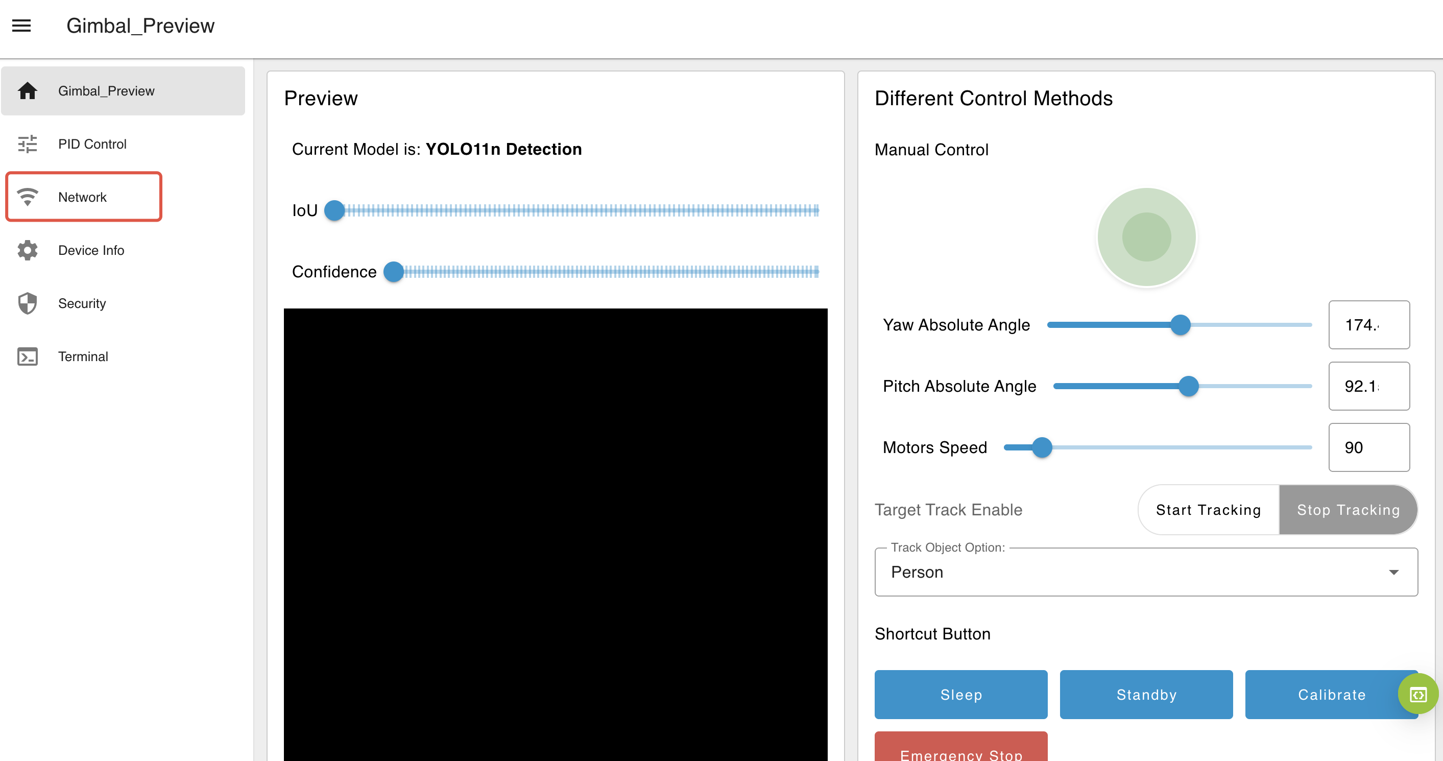
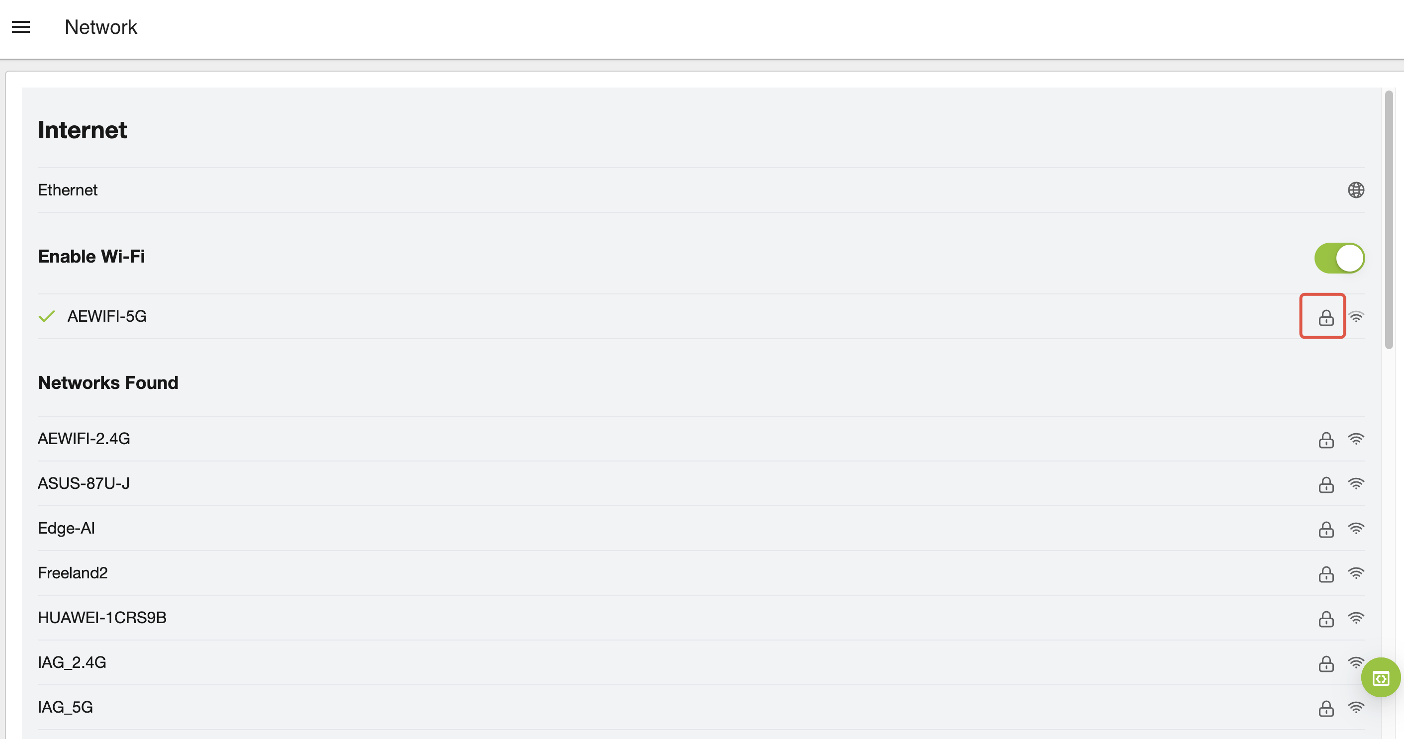
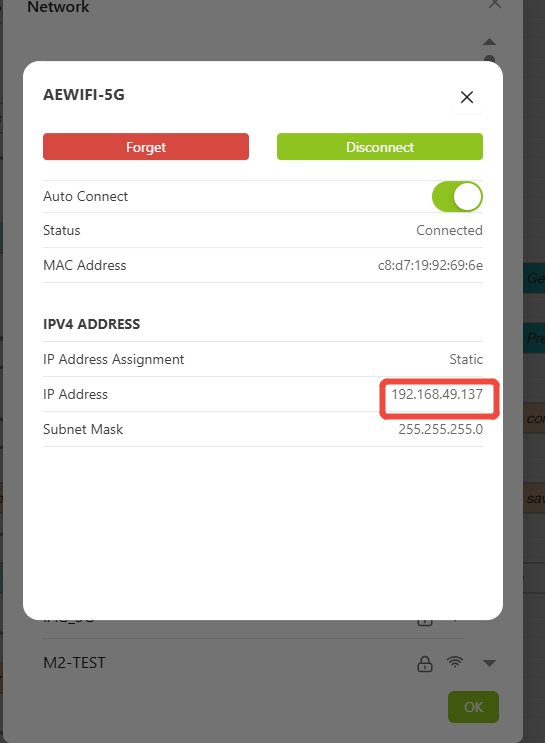
Step3: Connect to your Wi-Fi. After successfully connect to Wi-FI, click the lock icon to view the device IP address.
Step4: Open a new browser tab and use this IP address to access the device.
Step6: Connect the power to the base first, then remove the USB type C cable for best motor movements.
It should be connected the power adapter with voltage 12V.

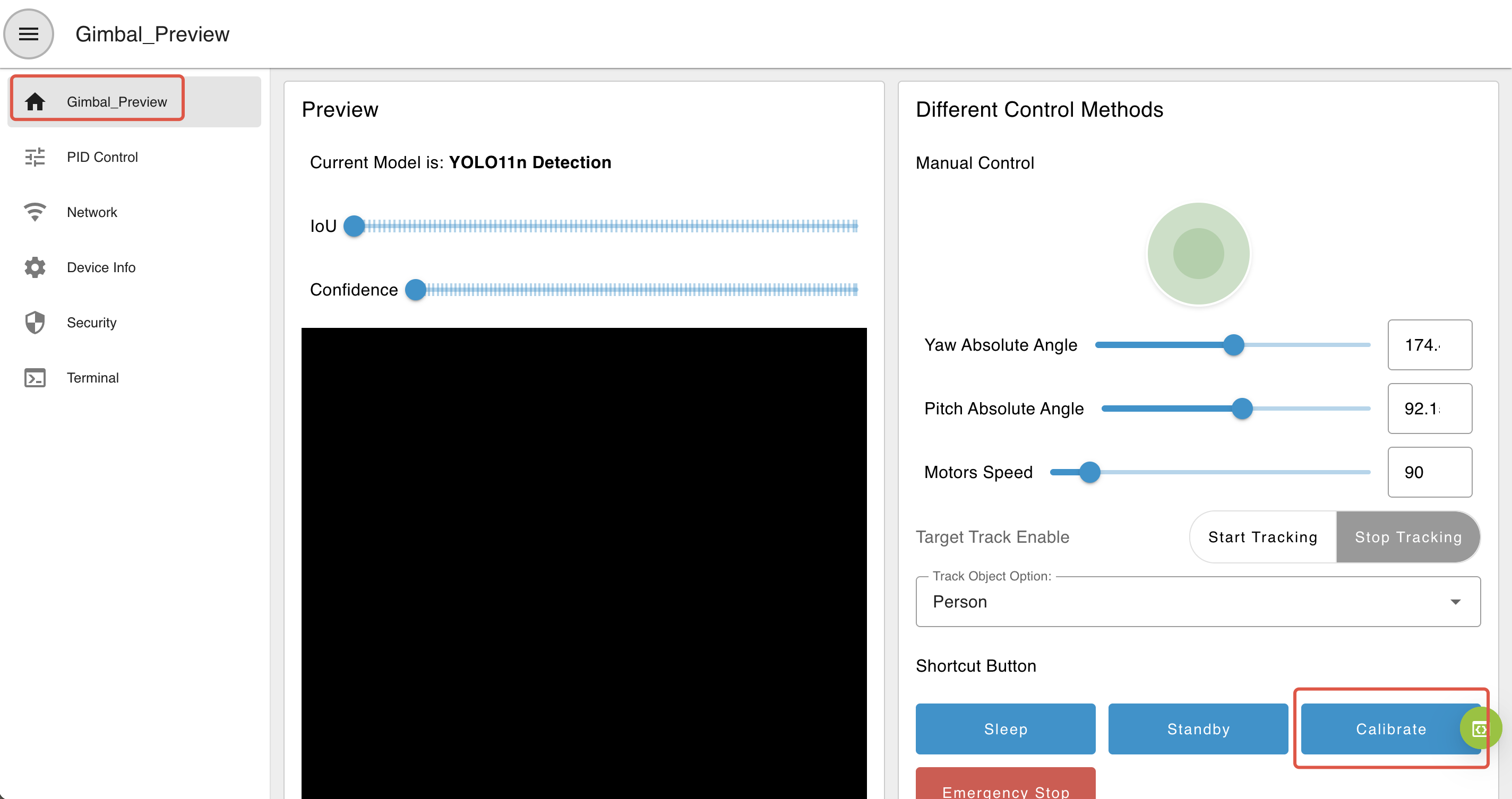
Step7: Go back to your ip address browser to visit the dashboard, then hit Calibrate button on the right side to let your Gimbal calibrate itself.
During calibration, avoid interfering with the device's operation as this could result in calibration failure. Calibration is performed automatically each time the gimbal is powered on.
Calibration Behavior
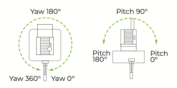
The yaw axis has a movement range of 0–360°, although the actual mechanical range is limited to approximately 345° due to structural constraints. However, the vision coverage remains 360°. The pitch axis supports a movement range of 0–180°.
Upon powering on, the gimbal will begin its automatic calibration sequence:
-
Yaw Axis: The gimbal will first rotate clockwise toward its mechanical limit (positioned above the power cable), then rotate counterclockwise to the opposite limit. After reaching both ends, it will return to the center position.
-
Pitch Axis: The gimbal will tilt upward to the 0° position, then downward to reach the 180° limit, and finally return to the center.

This sequence completes the gimbal's self-calibration process.
You can also calibrate by enter this command in the terminal
gimbal cali
Troubleshooting Calibration Issues
If the gimbal does not perform the calibration sequence correctly, there may be several potential causes:
-
Verify the Mechanical Limitations: Manually check the gimbal to ensure that the movement range is not obstructed or limited incorrectly.
-
Check Resistance From 3D Printed Parts: Feel for any resistance when the motor moves. If the resistance is excessive, you may need to adjust the motor's PID settings to increase motor force. You can view how to adjust PID here. Alternatively, reduce friction by sanding any parts or slightly loosening screws to improve movement.
Basic Web Access
Web urls:
-
Preview Page:
ip_address/#/dashboard -
Home Page:
ip_address/#/init -
Workspace:
ip_address/#/workspace -
Network Configuration:
ip_address/#/network -
Security:
ip_address/#/security -
Terminal:
ip_address/#/terminal -
System:
ip_address/#/system -
Power:
ip_address/#/power -
Original Node-RED:
ip_address:1880
Quick Start with Gimbal Dashboard
Motors control
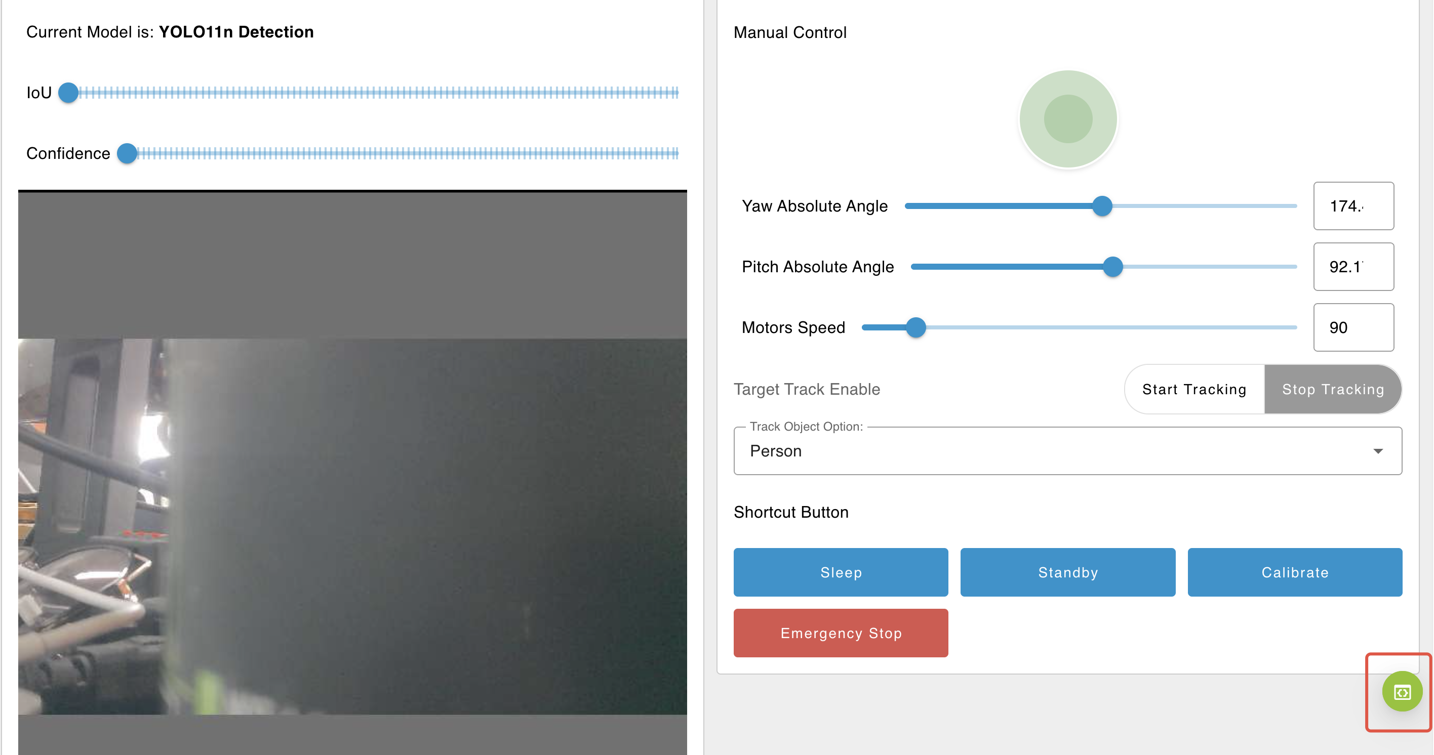
After setup and calibration are complete, you can control the gimbal using the available options in the dashboard. Visit ip_address/#/dashboard or ip_address to access Gimbal's preview dashboard made with Node-RED nodes:
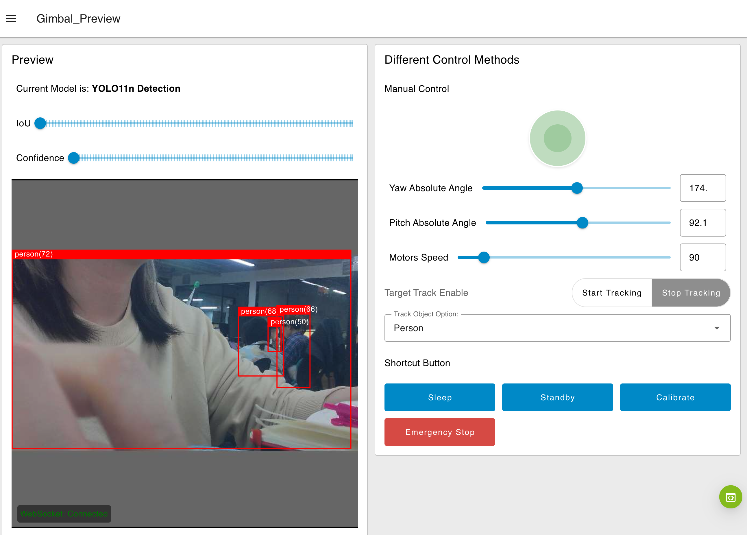
- Joystick: Controls the direction of the camera's view. For example, dragging the joystick to the right causes the image to move right accordingly.
- Sliders:
-
Yaw and Pitch Sliders: Move the gimbal to a specified absolute angle.
Yaw range: 0–360°
Pitch range: 0–180°
-
Due to structural constraints, the yaw range is limited to 0–345° and the pitch range is limited to 0–180°. Any values entered outside of these ranges will be adjusted to the closest boundary. For example, if you input 360° for yaw, the system will automatically execute the movement as 345°.
-
Speed Slider: Adjusts the speed of both motors simultaneously.
Speed range: 0–720°/s (degrees per second)
-
Auto-Tracking: Select a target object from the dropdown menu (e.g., person, car, cat, dog, bottle), then click
Start Trackingto initiate automatic object tracking. ClickStop Trackingto end tracking.
- Sleep Button: Moves the gimbal to an absolute position of (Yaw: 180°, Pitch: 180°).
The Sleep button does not activate a low-power sleep mode. It simply repositions the camera to face downward.
-
Standby Button: Moves the gimbal to an absolute position of (Yaw: 180°, Pitch: 90°).
-
Calibrate Button: Initiates the gimbal calibration process.
-
Emergency Stop Button:Immediately disables both motors during movement.
⚠️ Note: This will not interrupt the calibration process.
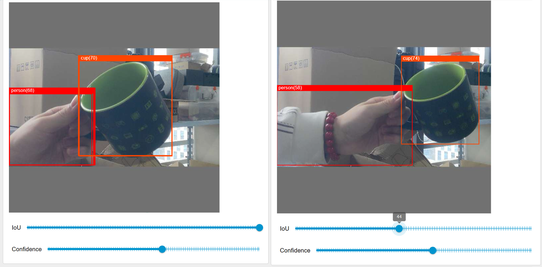
AI Model Parameters
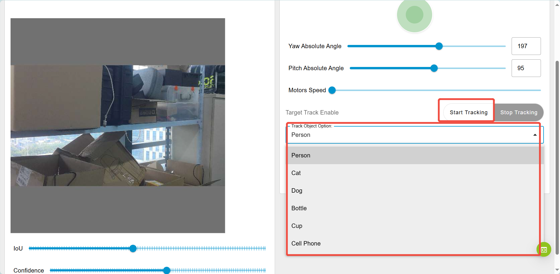
Confidence: Confidence in the YOLO model represents the probability that a predicted bounding box contains an object and how accurate the prediction is. It is a value between 0 and 100.
Intersection over Union (IoU): IoU is a metric used to evaluate the overlap between the predicted bounding box and the ground truth bounding box. It is calculated as the ratio of the intersection area of the two boxes to the union area of the two boxes. The value of IoU is typically in the range from 0 to 1. We standardized it to a scale of 0 - 100, an IoU value of 0 represents no overlap between the predicted box and the ground - truth box. A value of 100 indicates a perfect match, meaning the two boxes completely overlap.
Quick start with Gimbal Dashboard Flow
If you would like to know how the dashboard is made with Node-RED nodes, click the bottom right corner or visit ip_address/#/workspace to access Gimbal's Node-RED workspace
Then you will see the default gimbal dashboard flow, you can double click in each node to view the detail of the node. The dashboard flow will look like this:
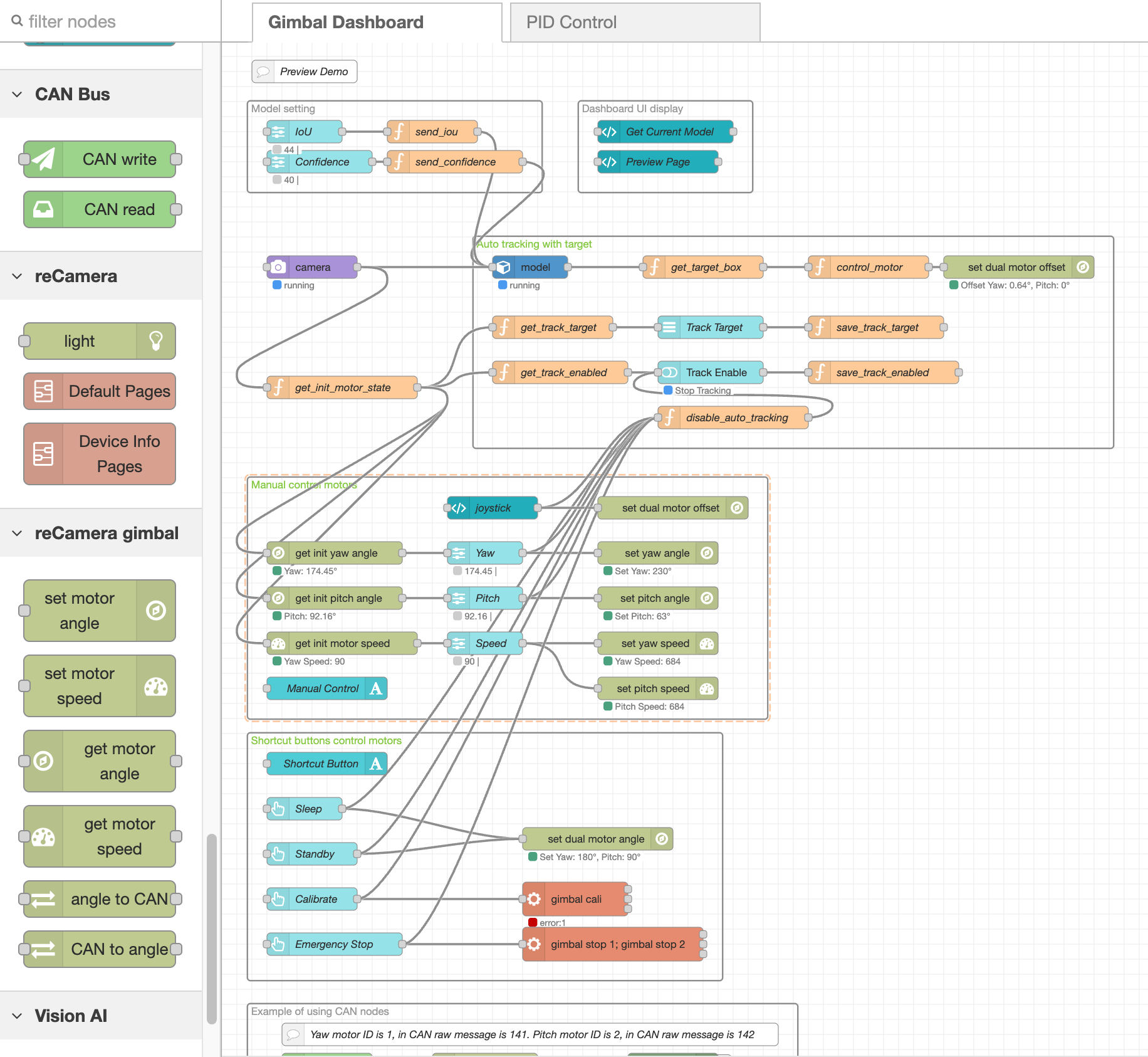
Model Settings:
- Slider nodes allow you to adjust the IoU (Intersection over Union) and confidence threshold for the YOLO AI model.
Dashboard UI Display:
- The UI template node displays text showing the current model settings.
- It also renders the base64 image from the camera, including detection boxes for objects identified by YOLO.
Auto Tracking with Target:
-
Function nodes retrieve information about the target object (e.g., width, height, coordinates) and process this data using a tracking algorithm.
-
The algorithm function node calculates the offset of the target box center relative to the vision center and sends this offset to the set motor angle node to move the gimbal to the desired position.
Manual Motor Control:
-
Use slider nodes to manually set motor angles, moving the gimbal by a specific degree.
-
Alternatively, the joystick UI node allows manual control by adjusting the gimbal's position in small increments (offset-by-offset).
Shortcut Buttons:
-
Button UI nodes send specific positions to the set motor angle node, triggering behaviors like Sleep or Standby.
-
These buttons can also trigger exec nodes running bash scripts such as
gimbal califor calibration orgimbal stop 1; gimbal stop 2for an emergency stop.
Basic Web Iframe Subflow:
-
An iframe subflow displays basic web pages like network settings, system info, and device information.
-
Note that these may consume CPU resources as it renders the page with multiple nodes. It can be deleted if not needed.
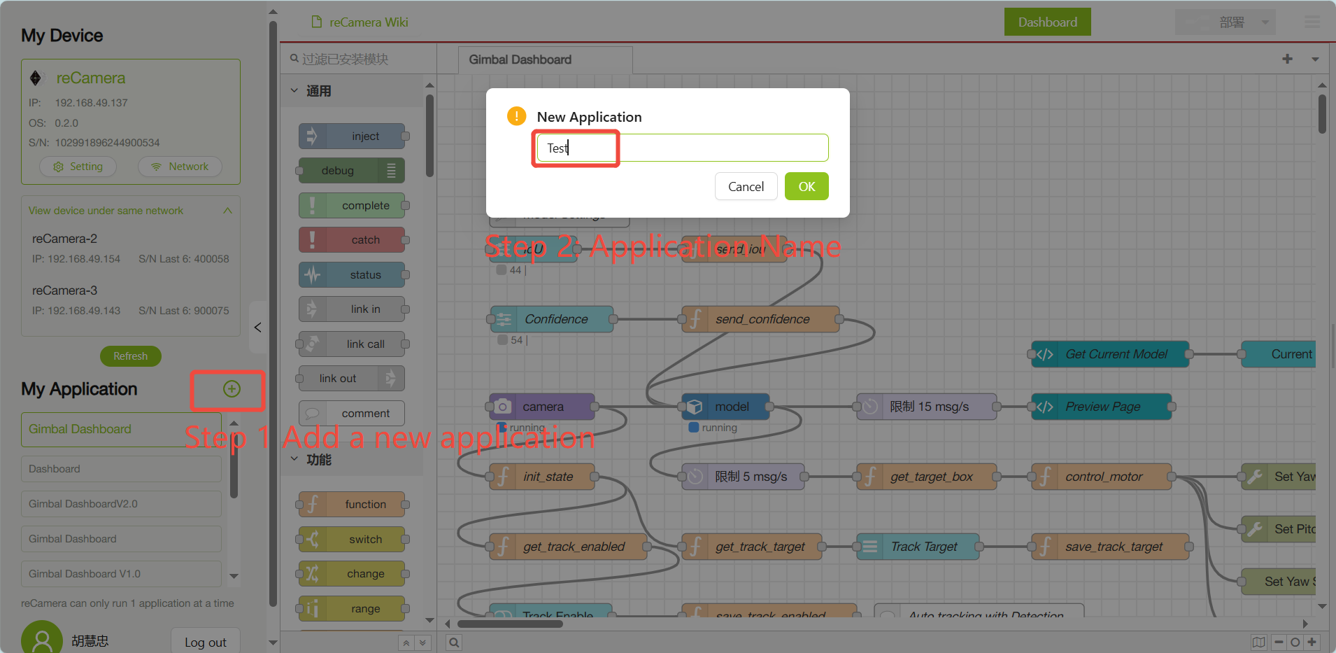
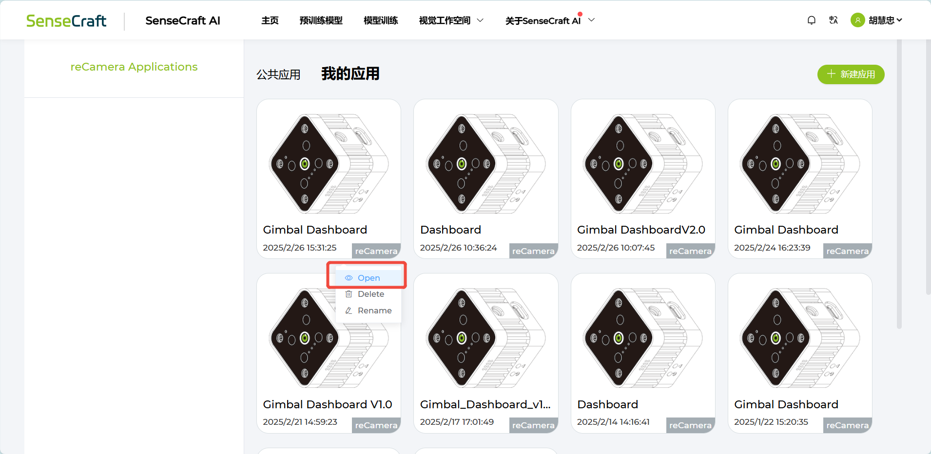
Apply cloud management and backup
If you would like to create new application or save applications to SenseCraft cloud service, you can login sensecraft account at the bottom left, and then click the + icon sign to add a new application. Then you can start working on your flow.
You can view and manage your apps reCamera - SenseCraft AI.
You need to register an account before you can login through the platform to sync your applications.
Port List
The following lists the ports used by reCamera Gimbal:
- Port 22: Utilized for remote SSH login and is open.
- Port 53: Associated with DNS domain name resolution and is essential for web redirection. It is open by default.
- Port 80: Serves as the web dashboard interface for HTTP display of the Node-RED Application.
- Port 554: Employed for RTSP video streaming.
- Port 9090: Intended for web terminal access, which requires a password for login.
- Port 1880: Dedicated to Node-RED operations.
OTA OS upgrade
Please refer to the OTA Upgrade Instruction.
Factory Reset
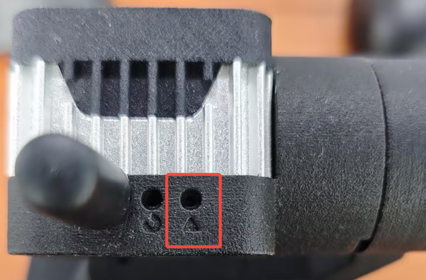
If you would like to reset the device such as forgetting your device's passcode, you can long pressing the User button and then connecting the device to power. When the red light of the device is constantly on instead of blinking, release the User button.
Resources
Tech Support & Product Discussion
Thank you for choosing our products! We are here to provide you with different support to ensure that your experience with our products is as smooth as possible. We offer several communication channels to cater to different preferences and needs.