Node-RED Introduction for Gimbal
This wiki provides step-by-step guidance on how to use Node-RED nodes to operate and control the motors on the gimbal. The default flow on the Device is a more comprehensive example of how you can use UI nodes with gimbal nodes, but we are going to break down the nodes one by one to explain how you can use it.
If you're new to Node-RED, or if you're interested in learning how to integrate Vision AI with gimbal control, please refer to this page.
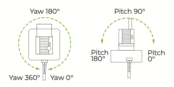
Please also be awared of the axis range for Gimbal as the image shown below:
Nodes
Set motor angle
This node allows you to set the gimbal to a specific angle by passing in target values for the motors. When an angle is provided, the gimbal will move accordingly to perform the desired positioning.
Example: Use an inject node to move the yaw motor to 50°

Configuration
- Name: Custom naming for the node.
- Input: freely Parse in the angle value by msg, flow, or global variable.
- Unit: Input value format:
- Input in decimal: Input values are in decimal degrees (e.g., 180.23°)
- Input in integer: Input values are in integer format representing hundredths of degrees (e.g., 18023 = 180.23°)
- Motor Selection: Choose which motor to control and the control mode:
-
Yaw Axis (Left and Right): Horizontal movement
-
Pitch Axis (Up and Down): Vertical movement
-
Absolute Position: Set the motor to a specific angle
-
Relative Offset: Move the motor by a relative amount
-
- Set dual axis at the same time: Control both motors with a single command
- Absolute Position: Set both motors to specific angles
- Relative Offset: Move both motors by relative amounts
Input
For single-axis control, the input is a number representing the angle value.
For dual-axis control, the input should be a JSON object with this structure:
{
    "yaw_angle": value,           // Horizontal angle in degrees
    "yaw_speed": speed_value,     // Optional: 0-720
    "pitch_angle": value,         // Vertical angle in degrees
    "pitch_speed": speed_value    // Optional: 0-720
}
Output
This node does not produce any output messages. It only sets the motor angle and updates its status display to reflect the operation result.
Status Display
The node displays the current operation in its status:
- Processing: Blue dot with
Processingtext when command is being sent - Success: Green dot with details about the operation when completed successfully:
- Example for single axis:
Set Yaw: 90°orOffset Pitch: 10° - Example for dual axis:
Set Yaw: 90°, Pitch: 45°orOffset Yaw: 5°, Pitch: 10°
- Example for single axis:
- Error: Red ring with error message if setting fails
- Busy: Yellow ring with
Busytext if the node is already processing a command
Set motor speed
The node sets the speed value for either the yaw (horizontal) or pitch (vertical) motor. This speed setting is stored in the global context and used by other motor control nodes when sending movement commands using SocketCAN.
Example: use a slider node to have a UI slider to adjust the Yaw motor speed.

The dasboard is made by the following flow:

In this example, we want to make sure that we set the range to 1-720, which is the motor speed range. Also have to make sure what msg you are parsing to the next node. Here we choose msg.topic.

Since in the slider node we choose msg.topic, we have to make sure that we are receiving from msg.topic to repsonse with the slider.

Configuration
You can specify where to get the input value from:
- msg: A property of the incoming message (e.g., payload)
- flow: A flow context variable
- global: A global context variable
Motor Selection:
- Yaw Axis (Left and Right): Sets the speed for the horizontal movement motor
- Pitch Axis (Up and Down): Sets the speed for the vertical movement motor
Input
The input should be a numeric value representing the desired motor speed. The default speed value is 90 if no custom speed has been set. The value can be provided in the following formats:
- Number: 90
- String containing a number: "45"
Speed Units: The speed value is measured in dps/LSB (degrees per second / Least Significant Bit), which is the resolution of the motor's speed control. The valid range is 0 to 65535, with typical values between 50 and 720 for gimbal.
Speed reference values:
- Slow movement: 1-120
- Medium movement: 120-360
- Fast movement: 360-720
Output
This node does not produce any output messages. It only updates the following global context variables:
- Yaw motor: can$$currentYawSpeed
- Pitch motor: can$$currentPitchSpeed
The speed value is stored in hexadecimal format (e.g., 5A.00 for speed 90) in the global context.
The motor control nodes retrieve these values when sending commands through the CAN bus.
Status Display
The node displays the current speed setting in its status:
-
Green dot with
Yaw Speed: XorPitch Speed: Xwhen successfully set -
Red ring with error message if setting fails. The node will report errors in the following cases:
- Invalid input value (not a number)
- Empty input value
Get motor angle
The node retrieves the current position of either the yaw (horizontal) or pitch (vertical) motor and outputs the angle. This is useful for monitoring the current orientation of the camera or for implementing position-based logic in your flows.
Example: Using a button to get the current yaw motor angle position

The dasboard is made by the following flow:
The button UI node will trigger the get motor angle node, then parse the result for the text UI node.
You can also import the below json into an empty flow to obtain this example:
[{"id":"24bca102bda2cc7b","type":"ui-button","z":"4c965edca3cbeb30","group":"e339fda5d481fc57","name":"","label":"Get Angle","order":0,"width":0,"height":0,"emulateClick":false,"tooltip":"","color":"","bgcolor":"","className":"","icon":"","iconPosition":"left","payload":"","payloadType":"str","topic":"topic","topicType":"msg","buttonColor":"","textColor":"","iconColor":"","enableClick":true,"enablePointerdown":false,"pointerdownPayload":"","pointerdownPayloadType":"str","enablePointerup":false,"pointerupPayload":"","pointerupPayloadType":"str","x":180,"y":200,"wires":[["254d3292e774ea35"]]},{"id":"e339fda5d481fc57","type":"ui-group","name":"get angle","page":"d682a21c64a5b02a","width":"6","height":"1","order":1,"showTitle":true,"className":"","visible":"true","disabled":"false","groupType":"default"},{"id":"d682a21c64a5b02a","type":"ui-page","name":"Page 1","ui":"a6b81038728cf4fb","path":"/page1","icon":"home","layout":"grid","theme":"d7858d0ba6eee558","breakpoints":[{"name":"Default","px":0,"cols":3},{"name":"Tablet","px":576,"cols":6},{"name":"Small Desktop","px":768,"cols":9},{"name":"Desktop","px":1024,"cols":12}],"order":1,"className":"","visible":"true","disabled":"false"},{"id":"a6b81038728cf4fb","type":"ui-base","name":"My Dashboard","path":"/dashboard","appIcon":"","includeClientData":true,"acceptsClientConfig":["ui-notification","ui-control"],"showPathInSidebar":false,"headerContent":"page","navigationStyle":"default","titleBarStyle":"default","showReconnectNotification":true,"notificationDisplayTime":1,"showDisconnectNotification":true},{"id":"d7858d0ba6eee558","type":"ui-theme","name":"Default Theme","colors":{"surface":"#ffffff","primary":"#0094CE","bgPage":"#eeeeee","groupBg":"#ffffff","groupOutline":"#cccccc"},"sizes":{"density":"default","pagePadding":"12px","groupGap":"12px","groupBorderRadius":"4px","widgetGap":"12px"}}]
Configuration

Motor Selection:
- Yaw Axis (Left and Right): Retrieves the angle of the horizontal movement motor
- Pitch Axis (Up and Down): Retrieves the angle of the vertical movement motor
Unit:
- Output in decimal: Outputs the angle value in decimal degrees (e.g., 180.23°)
- Output in integer: Outputs the angle value in integer format representing hundredths of degrees (e.g., 18023 = 180.23°)
Input
Any input message will trigger the node to read the current motor angle. The content of the input message is not used.
Output
The node outputs the current angle value in the msg.payload property:
// With "Output in decimal" selected
{
    "payload": 90.5
}

// With "Output in integer" selected
{
    "payload": 9050
}
Units:
- Raw Integer Value: Motor units (hundredths of degrees, 0-36000 for yaw, 0-18000 for pitch)
- Converted decimal Value: Degrees (0° to 360° for yaw, 0° to 180° for pitch)
Status Display
The node displays the current angle in its status:
- Blue dot with
Readingwhile querying the motor - Green dot with
Yaw: X°orPitch: X°when successfully retrieved - Yellow ring with
Busyif another query is already in progress - Red ring with error message if retrieval fails
- Communication error with the motor
- Invalid response from the motor
- Concurrent requests (will show
Busystatus)
Get motor speed
The node reads the current speed value stored in the global context for either the yaw (horizontal) or pitch (vertical) motor. This speed value is used by other motor control nodes when sending movement commands using SocketCAN.
Example: Use an injection node to get the motor speed and parse to the debug window

By clicking the inject node, you will see the current yaw motor speed in the debug window.
Configuration
- Yaw Axis (Left and Right): Retrieves the speed setting for the horizontal movement motor
- Pitch Axis (Up and Down): Retrieves the speed setting for the vertical movement motor
- The speed value is measured in
dps/LSB(degrees per second / Least Significant Bit), which is the resolution of the motor's speed control. The valid range is 0 to 65535, with typical values between 50 and 720 for gimbal.
Input
Any input message will trigger the node to read the current motor speed from global context. The content of the input message is not used.
Output
The node outputs the current speed value in the msg.payload property:
{
  "payload": 90
}
Status Display
The node displays the current speed value in its status:
- Green dot with
Speed: Xwhen successfully retrieved - Red ring with error message if retrieval fails
Angle to CAN
The node takes a numeric angle value as input and generates a CAN message object that can be sent directly to a CAN bus interface or to a CAN Write node.
Example: Use inject nodes to let yaw axis to rotate 30 degrees clockwise or counterclockwise. The angle to CAN node will convert the number into CAN command, and use CAN Write to operate the command.

You can set the message payload in the inject node as below:


and set the angle to CAN node for relative offset:

For CAN write, simply add the default client and select the client.
Configuration
- Motor Selection: Choose which motor to control and the control mode:
-
Yaw Axis (Left and Right): Horizontal movement
-
Pitch Axis (Up and Down): Vertical movement
-
Absolute Position: Set the motor to a specific angle
-
Relative Offset: Move the motor by a relative amount
-
- Unit: Input value format:
- Input in decimal: Input values are in decimal degrees (e.g., 180.23°)
- Input in integer: Input values are in integer format representing hundredths of degrees (e.g., 18023 = 180.23°)
Input
Specify the source of the angle value:
- msg.xxx: Use the value in the msg
- flow.xxx: Use a value from flow context
- global.xxx: Use a value from global context
The input should be a numeric value representing the target angle (for absolute positioning) or angle offset (for relative angle movement).
Examples:
90.5 - Move to 90.5 degrees (when using decimal degrees) 9050 - Move to 90.5 degrees (when using motor units) -10 - Move 10 degrees counterclockwise (when using relative offset) 10 - Move 10 degrees clockwise (when using relative offset)
Output
The node outputs a CAN message object that can be sent directly to a CAN bus:

{
  "payload": {
    "id": 0x141,  // Motor ID in hex format (0x141 for Yaw, 0x142 for Pitch)
    "data": [0xA4, 0x00, 0x5A, 0x00, 0x10, 0x27, 0x00, 0x00]  // Command data as byte array
  }
}
Note: the 321 is the hex format of yaw motor (ID 141), 322 is the hex format of pitch motor (ID 142).
Command Format
The output CAN message follows this format, for details, please visit latest motor manual:
Absolute Position Command
- Byte 0: Command type (0xA4)
- Byte 1: Direction (0x00)
- Byte 2-3: Speed (2 bytes, little-endian)
- Byte 4-7: Angle (4 bytes, little-endian)
Relative Offset Command
- Byte 0: Command type (0xA8)
- Byte 1: Direction (0x00)
- Byte 2-3: Speed (2 bytes, little-endian)
- Byte 4-7: Offset (4 bytes, little-endian)
Angle Limits
- Yaw: -180° to +180°
- Pitch: -90° to +90°
Values outside these ranges will be automatically limited to the allowed range.
Status Display
The node displays the current angle in its status:
- Green dot with
command ID+motor ID+move degrees
Can Write
The CAN Write node allows you to send command frames to CAN bus devices and receive their response frames. It's particularly useful for querying device status, sending control commands, and monitoring responses from CAN bus devices.
The example of usage is shown above with angle to CAN node.
Configuration
- Name: Optional name for the node
- Client: Select the CAN bus configuration to use (must be configured in a CAN-config node)
Input
The input supports two formats:
Format 1: String Format (Recommended)
A string in the format: ID#DATA where ID is the CAN identifier in hexadecimal and DATA is dot-separated hex bytes.
Example: 141#c1.0a.64.00.00.00.00.00
Format 2: Object Format
An object with the following structure:
{
  "id": "141",
  "data": ["A4", "00", "2C", "01", "50", "46", "00", "00"]
}
Where:
- id: The CAN identifier as a string (in hexadecimal without 0x prefix)
- data: Array of data bytes in hexadecimal (without 0x prefix)
Output
The node outputs an object with the following structure: (For each CAN command details, please visit latest motor manual)
{
  "payload": "141#90.00.AB.02.3C.4C.91.49",
  "details": {
    "id": "141",
    "data": ["90", "00", "AB", "02", "3C", "4C", "91", "49"],
    "raw": "90.00.AB.02.3C.4C.91.49"
  },
  "timestamp": 1632048172456,
  "topic": "can-response"
}
Where:
- payload: String in the format
ID#DATA - details: Object containing detailed information:
- ID: The CAN identifier (same as request)
- data: Array of response bytes in hexadecimal
- raw: Dot-separated string of the response bytes
- timestamp: Time when the response was received
- topic: Set to "can-response"
Example
Request (Input string):
141#90.00.00.00.00.00.00.00
Response (Output):
{
  "payload": "141#90.00.AB.02.3C.4C.91.49",
  "details": {
    "id": "141",
    "data": ["90", "00", "AB", "02", "3C", "4C", "91", "49"],
    "raw": "90.00.AB.02.3C.4C.91.49"
  },
  "timestamp": 1632048172456,
  "topic": "can-response"
}
Response Handling
The node waits for a response from the CAN device and automatically filters response frames to ensure you receive the relevant response to your specific command.
Timeout
If no response is received within the configured timeout period, the node will output an error message.
Error Handling
The node will report errors in the following cases:
- Invalid input format
- CAN bus communication error
- Response timeout
CAN to Angle
The node takes a CAN message object as input and extracts the motor ID, command type, and angle/offset value. It supports absolute position commands (A4), relative offset commands (A8), and status query commands (94).

Configuration
The Input field allows you to specify the message property, flow context, or global context variable that contains the CAN message object. By default, it uses msg.payload.
Input
The input should be a CAN message object with the following structure:
{
  "id": 0x141,  // Motor ID in hex format (0x141 for Yaw, 0x142 for Pitch)
  "data": [...]  // Byte array containing the command data (8 bytes)
}
Example:
{
  "id": 0x141,
  "data": [0xA4, 0x00, 0x5A, 0x00, 0x10, 0x27, 0x00, 0x00]
}
Command Validation
The node includes advanced validation to ensure only meaningful data commands are processed:
- 94 commands: Must NOT have all remaining bytes as zero (which would indicate a query, not a response)
- A4/A6 commands: The second byte must be 0x00 or 0x01 to be considered valid (excludes ACK responses like 0x2F)
- A8 commands: The second byte must be 0x00 to be considered valid
These validation rules prevent processing ACK responses and query commands that would result in incorrect angle calculations.
Unit
- Output in decimal: Outputs angle values in decimal degrees (e.g., 180.23°)
- Output in integer: Outputs angle values in integer format representing hundredths of degrees (e.g., 18023 = 180.23°)
Output
The node outputs a JSON object with the decoded information:
For absolute position commands (A4) with "Output in decimal" selected:
{
    "payload": {
        "motorId": 0x141,
        "angle": 90.5
    }
}
For absolute position commands (A4) with "Output in integer" selected:
{
    "payload": {
        "motorId": 0x141,
        "angle": 9050
    }
}
For relative offset commands (A8) with "Output in decimal" selected:
{
    "payload": {
        "motorId": 0x142,
        "offset": 5.0
    }
}
For status query commands (94) with "Output in decimal" selected:
{
    "payload": {
        "motorId": 0x141,
        "status": true,
        "angle": 90.5
    }
}
Motor IDs
- Yaw motor (horizontal):
0x141 - Pitch motor (vertical):
0x142
Command Types
0xA4: Absolute position command0xA8: Relative offset command0x94: Status query command
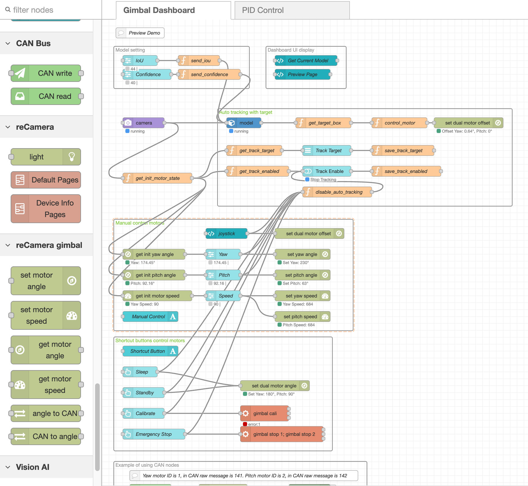
Explanation of the Default Flow
The default flow is an example of how you can use dashboard UI palette, vision AI palette, and reCamera palette to form a dashboard that can preview camera, track specific objects, and control motors. The dashboard looks like this:
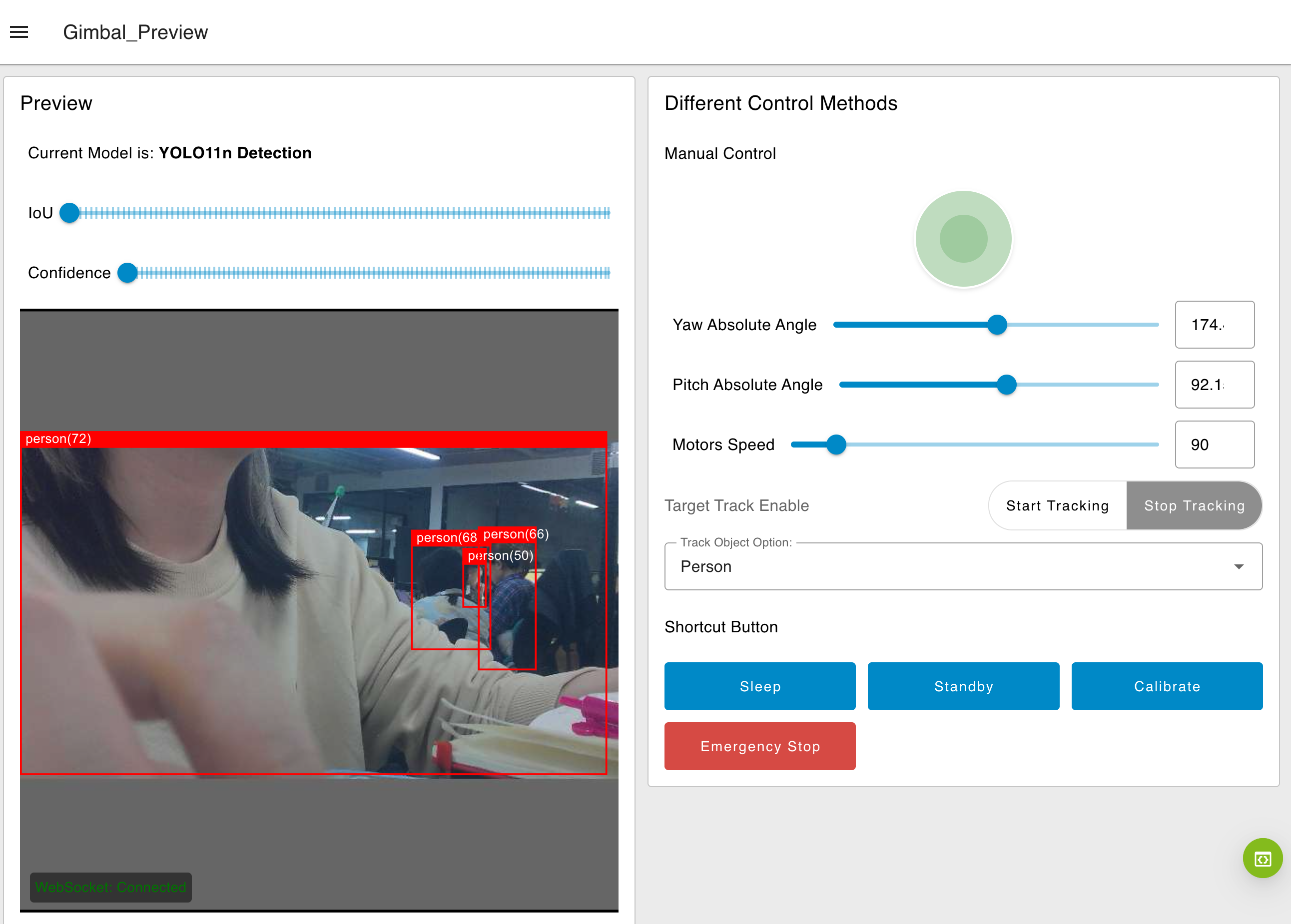
We will break down each individual functions to help you understand this flow more.
Auto Tracking
This section of the flow handles the auto-tracking functionality.
-
Model Node: runs the YOLO model and outputs detection results such as x, y, w, h, object ID of the detection box. -
Function get_target_box Node: the function node extracts only the bounding boxes information for the desired object. The algorithm selects the largest bounding box, typically the closest or most relevant target to track. -
Function control_motor Node: calculate offset between the center of this bounding box and the center of the camera frame. -
Set motor offset Node: receive the offset value, then parse the CAN command to motors to keep the target centered in the frame. -
Function get_track_target Node: Match the object ID in Yolo algorithm with the actual object name and update the global variabletrackTarget. -
Dropdown List UI Node:Provide the dropdown List UI in the dashboard. Users can select TrackTarget in real-time. -
Function save_track_target Node: Update the TrackTarget from the dropdown list interaction. -
Function get_track_enable Node: Get the status of global variabletrackEnabled. -
Track Enable Button Group Node: Provide the toggle button UI in the dashboard for users to enable or disable the auto tracking. -
Function save_track_enabled Node: Update the global variabletrackEnabledis enabled or not.
Manual control
The manual control flow allows users to move the gimbal motors by interacting with UI sliders.

-
Joystick Node: Used the template UI node to draw out an interaction joystick, which will parse the movement data to the next node. -
Set dual motor anle Node: Select the set dual axis at the same time config. Use the parsed-in json from Joystick to control the motor movement at the same time. Please noted that this control the movement of the image rather than the actual orientation of the physical gimbal. -
Get motor angle Node: Retrieve the initial positions of yaw and pitch motor when the device powers on and synchronize with the slider UI node.
-Get motor speed Node: Retrieve the initial speed of yaw motor when the device powers on and synchronize with the slider UI node.
-
Slider UI Node: Provide a slider UI on dashboard for user to interact with the motors. Noted that we only use one speed slider here to control both motor speed at the same time. You can use 2 nodes to assign different speed for two motors. -
Set motor angle Node: Receive data from the slider UI node, and parse the CAN command to execute the motor to certain position. -
Set motor speed Node: Receive data from the slider UI node, and update the global variable for motor speed to be ready to sent with a position command.
Shortcut buttons

Button UI Node: Provide button UI on dashboard for user to interact with the gimbal. While clicking, the node will send out the assigned value:-
Sleep:
{"yaw_angle":180, "yaw_speed":360, "pitch_angle":175, "pitch_speed":360} -
Standby:
{"yaw_angle":180, "yaw_speed":360,"pitch_angle":90, "pitch_speed":360} -
Calibrate: trigger the exec node
-
Emergency Stop: trigger the exec node
-
By clicking these buttons, the trackEnabled will also be updated to disable to stop auto-tracking (if it is on).
Exec Node: Runs a system command and returns its output. You can execute any bash script for gimbal for this node:-
Calibrate:
gimbal cali -
Emergency Stop:
gimbal stop 1; gimbal stop 2You can view all the available script if you enter
gimbalin the terminal.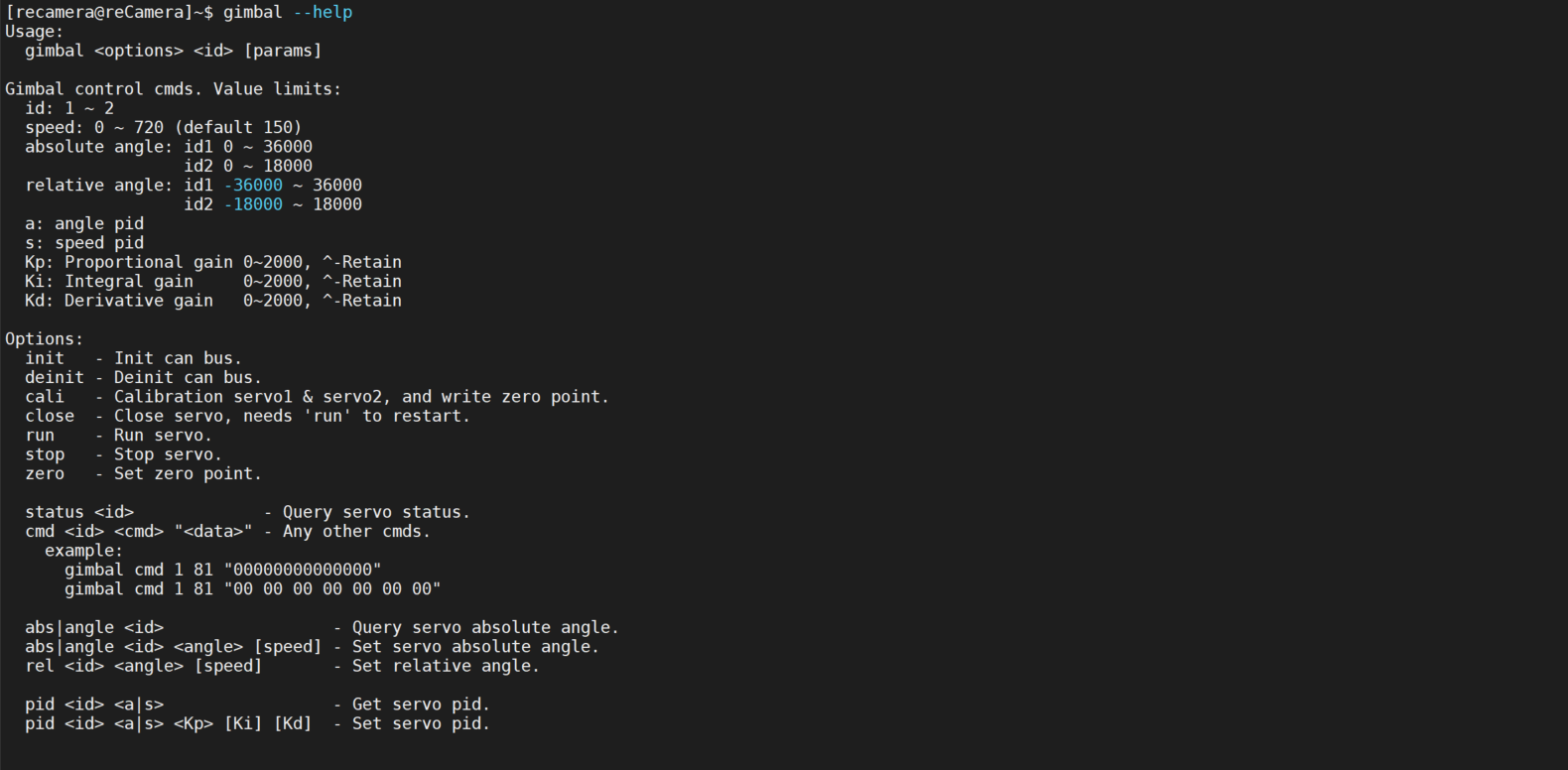
-
CAN Nodes
This example is not shown on the dashboard as it does not have any UI nodes. It is a example in the workspace to demonstrate how to use the following nodes.

-
CAN read Node: Continuously listen for CAN messages on the configured interface and outputs them in a standardized format. -
CAN to angle: Decode and convert the raw data read from CANbus to angular values. -
Inject Node: parse30degrees for theangle to CANnode to move dssthe motor. -
angle to CAN: Take a numeric angle value (30 in this case) as input and generates a CAN message object that can be sent directly to a CAN bus interface or to a CAN Write node. -
CAN Write: Send command frames to CAN bus devices and receive their response frames. In this case it will parse"payload": {
"id": 0x141, // Motor ID in hex format (0x141 for Yaw, 0x142 for Pitch)
"data": [0xA8, 0x00, 0x5A, 0x00, 0xb8, 0xb, 0x00, 0x00] // Command data as byte array
}to the CAN command to rotate 30 degrees counterclockwise.
PID Control
Please view the document here about PID nodes.
Tech Support & Product Discussion
Thank you for choosing our products! We are here to provide you with different support to ensure that your experience with our products is as smooth as possible. We offer several communication channels to cater to different preferences and needs.