Getting Start with reComputer AI Industrial R2135 Series
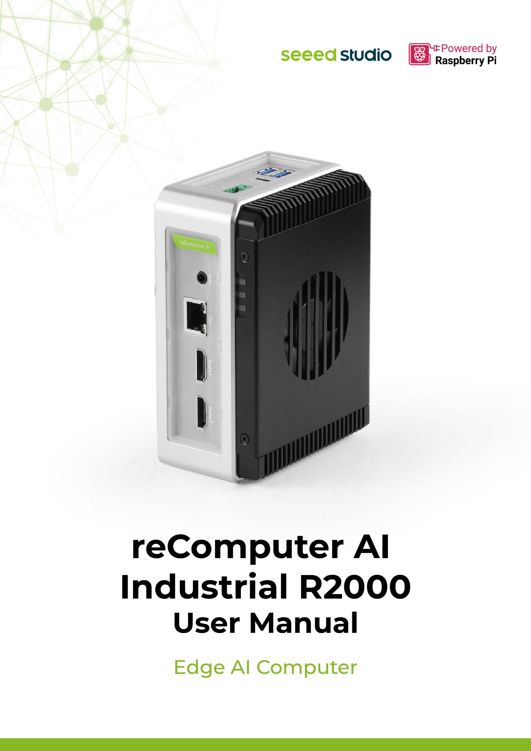
The reComputer AI Industrial R2135 is powered by Raspberry Pi CM5 and Hailo AI accelerator, this compact edge AI system delivers 26 TOPS for real-time multi-channel vision processing. With a quad-core Cortex-A76 CPU, up to 16GB RAM, 64GB eMMC, and a versatile interface, it ensures seamless integration into industrial AI applications.
Designed for 24/7 reliability, it features wide voltage input (9-36V), hardware watchdog, and robust cooling, operating stably in -20°C to 65°C environments. Ideal for smart factories, surveillance, and AIoT, this solution brings powerful AI computing to the edge.
Features
-
Industrial-Grade Reliability: Aluminum chassis with wide temperature support -20°C to 65°C, RTC, hardware watchdog, for stable 24/7 operation.
-
Powerful Performance: Powered by Raspberry Pi CM5 with quad-core Cortex-A76 CPU, up to 16GB RAM, 64GB eMMC.
-
High-Efficiency Al Computing: Powered by Hailo-8 Al accelerator up to 26 TOPS for multiple channel Al vision processing.
-
Extensive Connectivity: 2x HDMI2.0, 1x Giqabit Ethernet, 2x USB 3.2, 1x USB-C, dual M.2 slots, and Mini-PCle for 4G/LoRa expansion.
-
Versatile Wireless Options: Built-in Wi-Fi5, Bluetooth 5.0, and optional 4G LTE/LoRaWAN@.
-
Flexible Storage Options: The PCIe3.0 dual M.2 Slot supports both AI accelerator and SSD storage.
Specifications
| Category | Parameters |
|---|---|
| Hardware Spec | |
| CPU | Raspberry Pi Compute Module 5, 2.4GHz quad-core 64-bit Arm Cortex-A76 |
| GPU | Raspberry Pi Compute Module 5, VideoCore VII |
| AI Processor | Hailo-8 M.2 Acceleration Stick, 26 TOPS (Tera-Operations Per Second) |
| RAM | 8GB SDRAM |
| eMMC | 32GB |
| Operating System | Raspbian, Debian |
| System Spec | |
| Power Input | DC 9V~36V, 2-pin Terminal Block |
| Video Decoder | 4Kp60 HEVC Decoder |
| Interface | |
| Ethernet | 1x 10/100/1000 Mbps, RJ45 |
| USB | 2x USB 3.2 Ports (USB-A); 1x USB 2.0 Port (USB-C for debug/update OS) |
| Display | 2x Standard HDMI Ports, HDMI 2.0 |
| M.2 Slot | 1x USB 3.0 to M.2 (M-key 2280); 1x PCIe 3.0 to M.2 (M-key 2242) |
| Mini-PCIe | 1x Mini-PCIe for 4G/LoRaWAN module |
| SIM Card | 1x Standard SIM Card Slot |
| LED | 3x LEDs: Power / ACT / 4G |
| Button / Switch | 1x Reset Button; 1x Boot Switch |
| Wireless Communication | |
| Wi-Fi 2.4/5.0 GHz | On-chip Wi-Fi 5 |
| BLE 5.0 | On-chip BLE 5.0 |
| 4G Cellular | 4G LTE (Optional) |
| LoRa® | USB LoRa® / SPI LoRa® (Optional) |
| Ambient Conditions | |
| Ingress Protection | IP40 |
| Operating Temperature | -20°C to 65°C |
| Operating Humidity | 10% to 95% RH |
| Antenna | 3x Antenna Holes |
| Others | |
| Watchdog | Hardware Watchdog |
| RTC | High Accuracy RTC |
| Security | Encryption Chip TPM2.0 / ATECC608A (Optional) |
| Heat Dissipation | Heatsink with Fan |
| Warranty | 2 Years |
| Production Lifetime | Until December 2036 |
| Mechanical | |
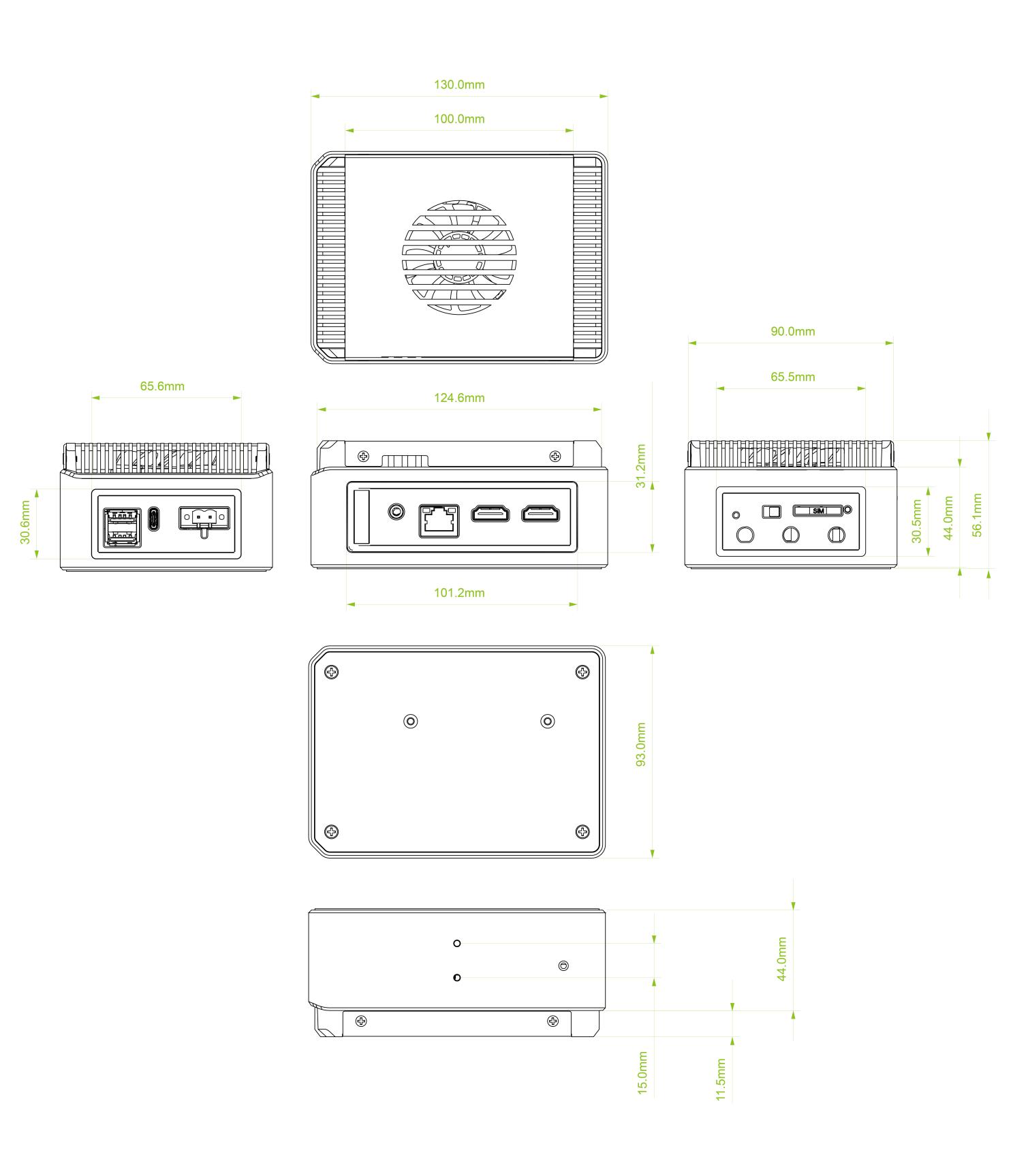
| Dimensions (W x H x D) | 130mm × 93mm × 55.5mm |
| Enclosure | Aluminum Alloy Casing with PC Side Panels |
| Mounting | DIN-rail / Wall Mount |
| Weight (Net) | 688g |
| Statement | Options marked "Optional" require additional purchase (refer to accessories list). |
Hailo introduction
Hardware introduction
Hailo offers cutting-edge AI processors uniquely tailored for high-performance deep learning applications on edge devices. The company's solutions focus on enabling the next era of generative AI on the edge, alongside perception and video enhancement, powered by advanced AI accelerators and vision processors. And The reComputer_R2000, equipped with the Hailo-8 NPU accelerator providing 26 TOPs of AI performance, is capable of achieving over 200 FPS with YOLOv8s.
Software introduction
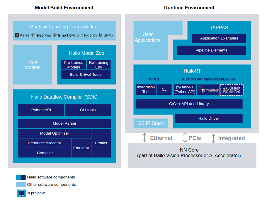
The Hailo AI Software Suite provides powerful tools to run AI models efficiently on hardware accelerators. It is designed to integrate seamlessly with existing deep learning frameworks, offering smooth workflows for developers.The process involves generating a HEF (Hailo Executable Binary File) from an ONNX file in the Model Build Environment. Once created, the HEF file is transferred to the inference machine (Runtime Environment), where it is used to execute inference with the HailoRT API. The provided script facilitates the conversion of an ONNX file into a HEF file within the Model Build Environment.
Note: If you want to learn more about examples of using Hailo NPU, please click this link.
Hardware Overview
Interface Overview

To query GPIO mappings and offsets, please use following command:
cat /sys/kernel/debug/gpio
GPIO information
gpiochip11: GPIOs 512-526, parent: platform/107d517c00.gpio, gpio-brcmstb@107d517c00:
 gpio-512 (RP1_SDA             )
 gpio-513 (RP1_SCL             )
 gpio-514 (RP1_RUN             |RP1 RUN pin         ) out hi
 gpio-515 (SD_IOVDD_SEL        )
 gpio-516 (SD_PWR_ON           |sd-vcc-reg          ) out hi
 gpio-517 (ANT1                |ant1                ) out hi
 gpio-518 (ANT2                |ant2                ) out lo
 gpio-519 (-                   )
 gpio-520 (2712_WAKE           )
 gpio-521 (2712_STAT_LED       |ACT                 ) out hi ACTIVE LOW
 gpio-522 (-                   )
 gpio-523 (-                   )
 gpio-524 (PMIC_INT            )
 gpio-525 (UART_TX_FS          )
 gpio-526 (UART_RX_FS          )

gpiochip12: GPIOs 527-532, parent: platform/107d517c00.gpio, gpio-brcmstb@107d517c20:
 gpio-527 (HDMI0_SCL           )
 gpio-528 (HDMI0_SDA           )
 gpio-529 (HDMI1_SCL           )
 gpio-530 (HDMI1_SDA           )
 gpio-531 (PMIC_SCL            )
 gpio-532 (PMIC_SDA            )

gpiochip10: GPIOs 533-564, parent: platform/107d508500.gpio, gpio-brcmstb@107d508500:
 gpio-533 (-                   )
 gpio-534 (2712_BOOT_CS_N      |spi10 CS0           ) out hi ACTIVE LOW
 gpio-535 (2712_BOOT_MISO      )
 gpio-536 (2712_BOOT_MOSI      )
 gpio-537 (2712_BOOT_SCLK      )
 gpio-538 (-                   )
 gpio-539 (-                   )
 gpio-540 (-                   )
 gpio-541 (-                   )
 gpio-542 (-                   )
 gpio-543 (-                   )
 gpio-544 (-                   )
 gpio-545 (-                   )
 gpio-546 (-                   )
 gpio-547 (-                   )
 gpio-548 (-                   )
 gpio-549 (-                   )
 gpio-550 (-                   )
 gpio-551 (-                   )
 gpio-552 (-                   )
 gpio-553 (PWR_GPIO            |pwr_button          ) in  hi ACTIVE LOW
 gpio-554 (2712_G21_FS         )
 gpio-555 (-                   )
 gpio-556 (-                   )
 gpio-557 (BT_RTS              )
 gpio-558 (BT_CTS              )
 gpio-559 (BT_TXD              )
 gpio-560 (BT_RXD              )
 gpio-561 (WL_ON               |wl-on-reg           ) out hi
 gpio-562 (BT_ON               |shutdown            ) out hi
 gpio-563 (WIFI_SDIO_CLK       )
 gpio-564 (WIFI_SDIO_CMD       )

gpiochip13: GPIOs 565-568, parent: platform/107d508500.gpio, gpio-brcmstb@107d508520:
 gpio-565 (WIFI_SDIO_D0        )
 gpio-566 (WIFI_SDIO_D1        )
 gpio-567 (WIFI_SDIO_D2        )
 gpio-568 (WIFI_SDIO_D3        )

gpiochip0: GPIOs 569-622, parent: platform/1f000d0000.gpio, pinctrl-rp1:
 gpio-569 (ID_SDA              )
 gpio-570 (ID_SCL              )
 gpio-571 (GPIO2               )
 gpio-572 (GPIO3               )
 gpio-573 (GPIO4               )
 gpio-574 (GPIO5               )
 gpio-575 (GPIO6               )
 gpio-576 (GPIO7               )
 gpio-577 (GPIO8               |spi0 CS0            ) out hi ACTIVE LOW
 gpio-578 (GPIO9               )
 gpio-579 (GPIO10              )
 gpio-580 (GPIO11              )
 gpio-581 (GPIO12              )
 gpio-582 (GPIO13              )
 gpio-583 (GPIO14              )
 gpio-584 (GPIO15              )
 gpio-585 (GPIO16              )
 gpio-586 (GPIO17              )
 gpio-587 (GPIO18              )
 gpio-588 (GPIO19              )
 gpio-589 (GPIO20              )
 gpio-590 (GPIO21              )
 gpio-591 (GPIO22              )
 gpio-592 (GPIO23              )
 gpio-593 (GPIO24              )
 gpio-594 (GPIO25              )
 gpio-595 (GPIO26              )
 gpio-596 (GPIO27              )
 gpio-597 (PCIE_PWR_EN         )
 gpio-598 (FAN_TACH            )
 gpio-599 (HOST_SDA            )
 gpio-600 (HOST_SCL            )
 gpio-601 (ETH_RST_N           |phy-reset           ) out hi ACTIVE LOW
 gpio-602 (PCIE_DET_WAKE       )
 gpio-603 (CD0_IO0_MICCLK      |cam0_reg            ) out lo
 gpio-604 (CD0_IO0_MICDAT0     )
 gpio-605 (RP1_PCIE_CLKREQ_N   )
 gpio-606 (ETH_IRQ_N           )
 gpio-607 (SDA0                )
 gpio-608 (SCL0                )
 gpio-609 (-                   )
 gpio-610 (-                   )
 gpio-611 (USB_VBUS_EN         )
 gpio-612 (-                   )
 gpio-613 (RP1_STAT_LED        |PWR                 ) out hi ACTIVE LOW
 gpio-614 (FAN_PWM             )
 gpio-615 (-                   |micclk1_hog         ) out hi
 gpio-616 (2712_WAKE           )
 gpio-617 (-                   |micdat1_hog         ) out hi
 gpio-618 (-                   )
 gpio-619 (-                   )
 gpio-620 (-                   )
 gpio-621 (-                   )
 gpio-622 (-                   )
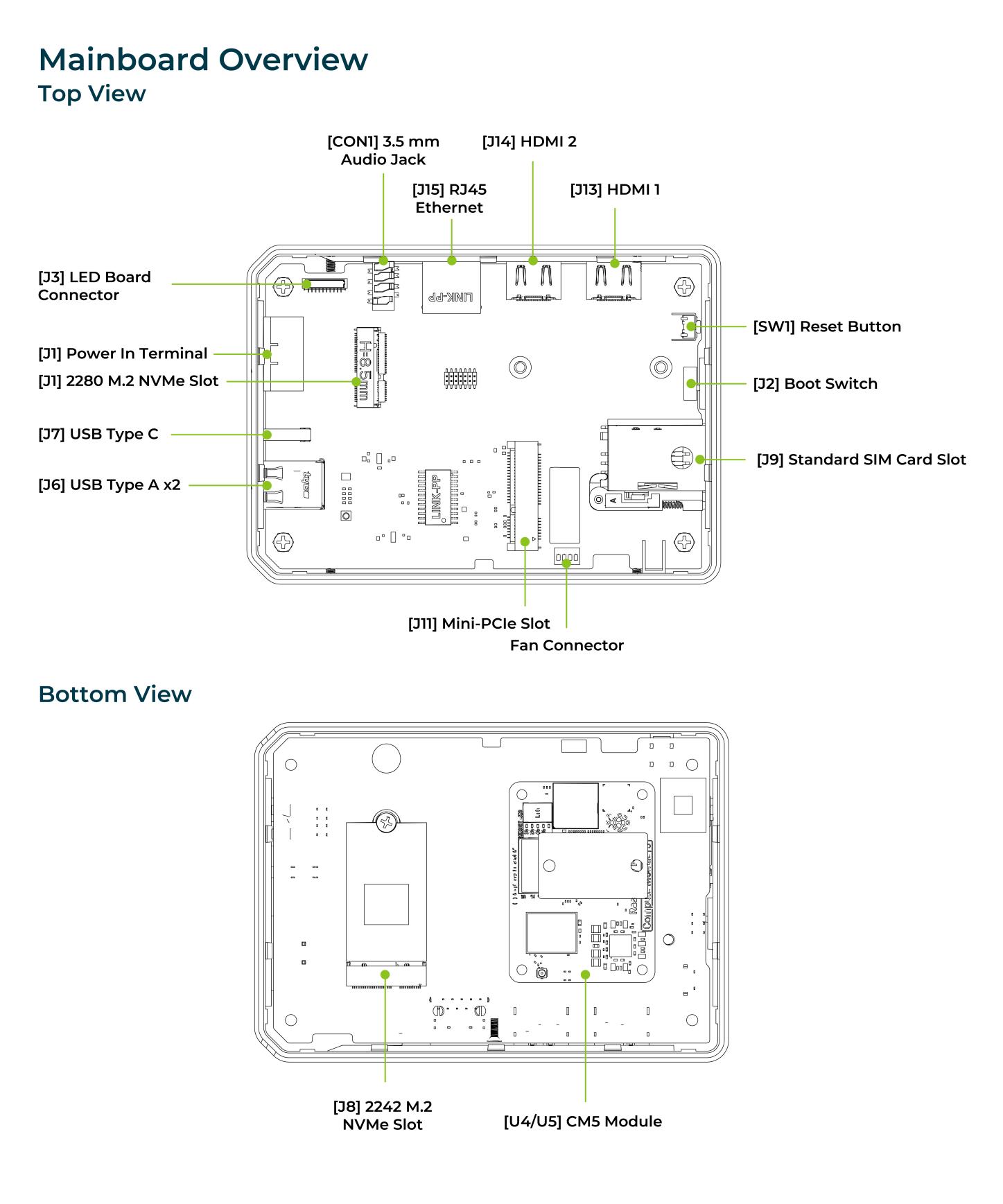
Mainboard Overview
Power Diagram

The reComputer AI Industrial R2135 supports a wide input voltage range of DC 9V–36V, and internally utilizes multi-stage DCDC converters to generate 5V, 3.3V, 1.2V, and 1.0V power rails. These voltages provide stable power to the core processor, USB ports, HDMI, M.2 expansions, audio, RTC, and other peripheral modules, ensuring reliable operation across various application scenarios.
2-Pin Power Terminal

The reComputer AI Industrial R2135 is supplied with a terminal DC voltage of 9~36V. The power supply is connected via the 2-pin power terminal block connector. To ground the reComputer AI Industrial R2135, the ground wire can be secured to the screw located at the top left corner of the power terminal.
Power Consumption
Please refer to the table below for the tested power consumption of reComputer AI Industrial R2135 in Seeed Studio's laboratory. Please note that this value is for reference only, as the test methods and environment can result in variations in the results.
| Status | Voltage | Current | Power Consumption | Description |
|---|---|---|---|---|
| Shutdown | 12V | 1.1mA | 0.013W | Static power consumption test in shutdown and power-off state. |
| Idle | 12V | 208mA | 2.42W | To test the input current when supplying 24V power to the reComputer AI Industrial R2135 device without running any test programs. |
| Full Load | 12V | 2.08A | 24.2W | Configure CPU to run at full load using the "stress -c 4" command. USB comes with a 1A load. |
Power On and Power Off
The reComputer AI Industrial R2135 does not come with a power button by default, and the system will automatically start up once power is connected. When shutting down, please select the shutdown option in the operating system and wait for the system to fully shut down before cutting off power. To restart the system, simply reconnect to the power.
Block Diagram

Interface
Interface Description
| Type | Description |
|---|---|
| Ethernet | 1x 10/100/1000 Mbps (supports POE*) |
| USB | 2x USB-A 3.2 Host; 1x USB-C 2.0 (for flashing OS) |
| HDMI | 2x HDMI 2.0 |
| Audio | 1x 3.5mm Audio output/input |
| SIM Card Slot | 1x SIM Card Slot, supports Standard SIM Card |
| M.2 Slot | 2x M.2 Slot, supports M.2 NVMe SSD and AI Acceleration |
| Mini-PCIe | 1x Mini PCIe Slot |
| LED | 3x LED indicators |
| Reset Button | 1x Reset Button |
| Boot Switch | 1x Boot Switch |
LED Indicator Status
The reComputer AI Industrial R2135 features 3 LED indicators that serve to signal the machine's operational status. Please refer to the table below for the specific functions and status of each LED:
| Name | Color | Status | Description |
|---|---|---|---|
| PWR | Green | On | The device has been connected to power. |
| Off | The device is not connected to power. | ||
| ACT | Orange | Under Linux this pin will flash to signify eMMC access. If any error occurs during booting, this LED will flash an error pattern (see Raspberry Pi Documentation). | |
| USER | Green/Red/Blue | Need to be defined by user. | |
| LTE | Green | On | The dial-up is successful and the connection is normal. |
| Off | LTE signal is not connected or the device is not powered on. |
ACT Status table
| Long flashes | Short flashes | Status |
|---|---|---|
| 0 | 3 | Generic failure to boot |
| 0 | 4 | start*.elf not found |
| 0 | 7 | Kernel image not found |
| 0 | 8 | SDRAM failure |
| 0 | 9 | Insufficient SDRAM |
| 0 | 10 | In HALT state |
| 2 | 1 | Partition not FAT |
| 2 | 2 | Failed to read from partition |
| 2 | 3 | Extended partition not FAT |
| 2 | 4 | File signature/hash mismatch - Pi 4 |
| 4 | 4 | Unsupported board type |
| 4 | 5 | Fatal firmware error |
| 4 | 6 | Power failure type A |
| 4 | 7 | Power failure type B |
If the ACT LED blinks in a regular four blink pattern, it cannot find bootcode(start.elf). If the ACT LED blinks in an irregular pattern then booting has started. If the ACT LED doesn't blink, then the EEPROM code might be corrupted, try again without anything connected to make sure. For more detail please check the Raspberry Pi forum: STICKY: Is your Pi not booting? (The Boot Problems Sticky) - Raspberry Pi Forums. For more detail please check the Raspberry Pi forum
To control the user LEDs, we recommend using sysfs, a pseudo-filesystem provided by the Linux kernel that exposes information about various kernel subsystems, hardware devices, and their associated drivers. On the ReComputer R2000, we have abstracted the user LED interface into three device files (led-red, led-blue, and led-green), enabling users to control the LED lights simply by interacting with these files. The examples are as follows:
- To turn on the red LED, please enter following command in the Terminal:
echo 1 | sudo tee /sys/class/leds/led-red/brightness
- To turn off the red LED, please enter following command in the Terminal:
echo 0 | sudo tee /sys/class/leds/led-red/brightness
- You can turn on red and green LED at the same time, please enter following command in the Terminal:
echo 1 | sudo tee /sys/class/leds/led-red/brightness
echo 1 | sudo tee /sys/class/leds/led-green/brightness
Boot Switch

The Boot Switch of The reComputer AI Industrial R2135 is connected to the nRPI_BOOT pin of CM5. This switch provides users with the option to select the boot source between eMMC and USB. In normal mode, the switch should be set away from the side with the "BOOT" label, enabling the system to boot from eMMC. Conversely, when users need to flash the system image, they should set the switch towards the "BOOT" label, allowing the system to boot from the Type-C USB interface.
| Switch Position | Mode | Description | nRPI-BOOT |
|---|---|---|---|
 | Normal mode | Boot from eMMC | Low |
| Flash mode | Boot from USB | High |
USB
The reComputer R2000 is equipped with one USB Type-C port and two USB Type-A ports. Please refer to the table below for their functions and descriptions.
| Type | Quantity | Protocol | Function | Description |
|---|---|---|---|---|
| Type-C | *1 | USB2.0 | USB-Device | Used for serial port debugging, burning image, etc. |
| Type-A | *2 | USB2.0 | USB-Host | Connect different USB devices such as flash drives, USB keyboards or mouses. |
Check if the USB hub is detected by running the lsusb command. This command lists all connected USB devices, including hubs.
lsusb
lsusb -t
Running this command should display information about the USB devices connected to your system, including any USB hubs that are present.
If the USB hub is functioning properly, you should see its details listed in the output of the lsusb command. If it's not listed, there may be an issue with the hub or its connection to the system. In such cases, you may need to troubleshoot the USB hub or its connections.
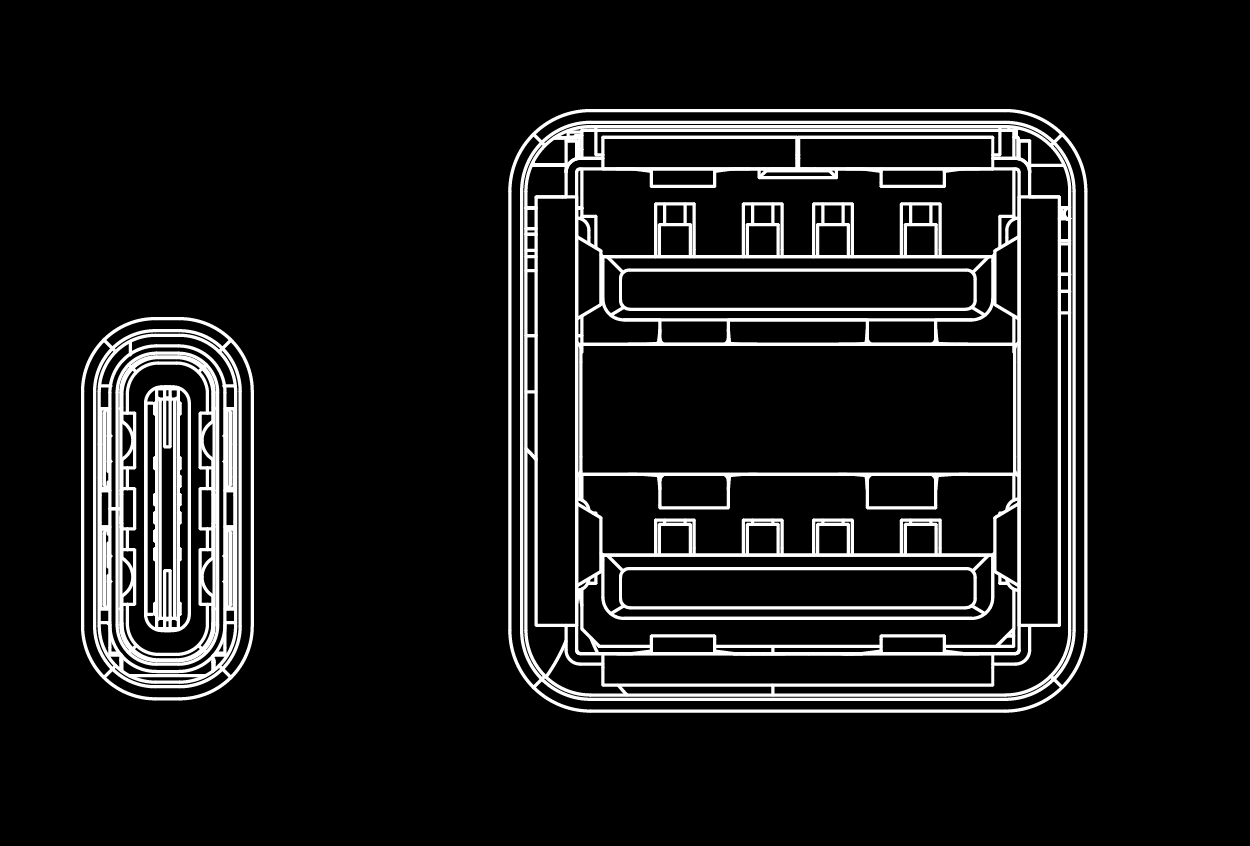
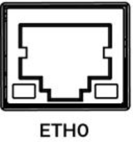
SIM Slot(Internal)
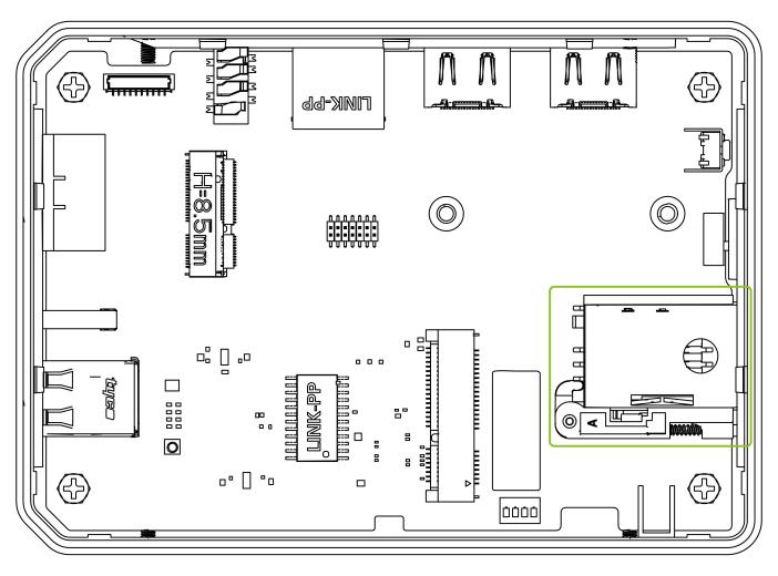
The reComputer AI Industrial R2135 series equipment includes an internal Standard SIM card slot, which is used to install Standard SIM card for obtaining 4G signals. The size differences between standard SIM, Micro SIM and Nano SIM cards are as follows:

Note
The standard version of reComputer AI Industrial R2135 does not come with a 4G module.
If you require 4G functionality, an additional 4G module must be purchased separately.
For more information, please refer to section "2.3.2 4G Module".
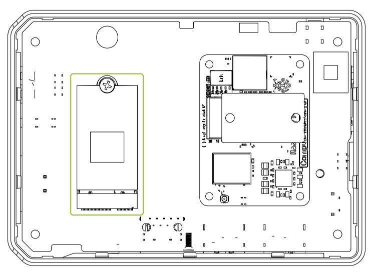
M.2 Slot
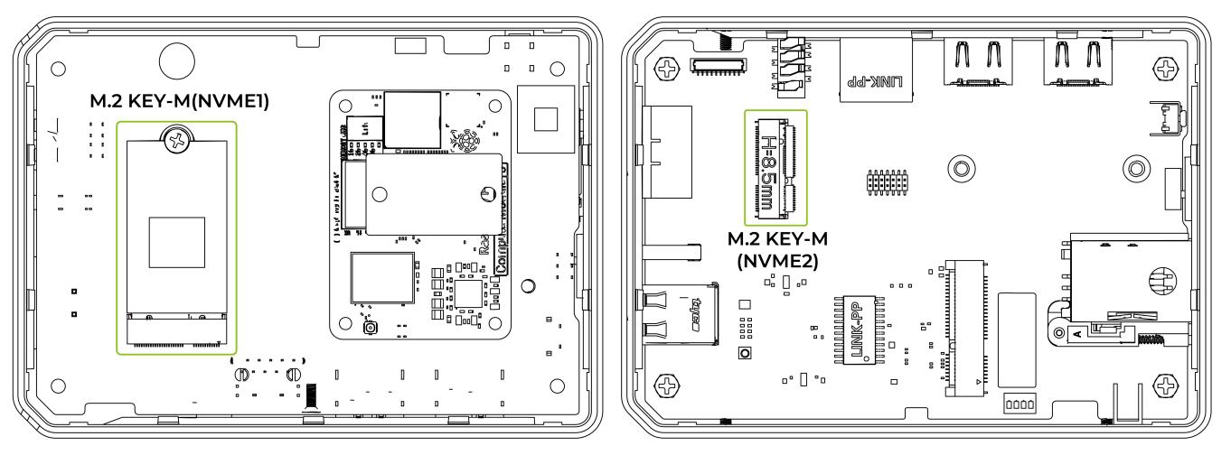
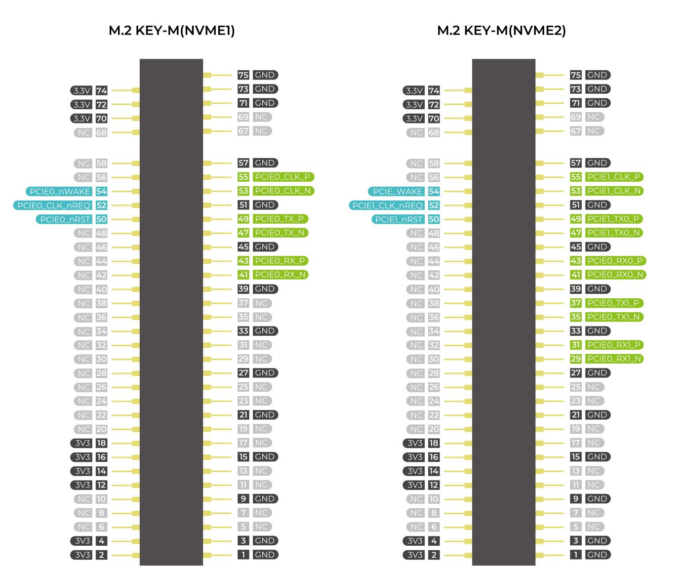
The reComputer AI Industrial R2135 is equipped with two M.2 Key-M slots (NVMe1 and NVMe2) for NVMe M.2 2280 SSD and AI Acceleration, allows for high-speed storage expansion, enabling users to enhance the performance and capacity of their system.
● NVMe1 (bottom slot): Supports M.2 2280 size;
● NVMe2 (top slot): Pre-installed with an Hailo-8 AI accelerator
● Only PCIe-based NVMe SSDs are supported. SATA SSDs are not supported.
Note
SSD cards have two primary uses:
- High-Capacity Storage – Used purely for storing large amounts of data.
- Boot Drive with Image – Used both for storage and to boot the system from an image stored on the SSD.
Not all SSD cards on the market support boot functionality.
If you plan to use an SSD as a boot drive and are unsure about compatibility, we recommend the 1TB SSD (SKU 112990267). This model has been tested and verified to support booting, helping avoid compatibility issues and reducing trial-and-error costs.
Mini-PCIe Slot
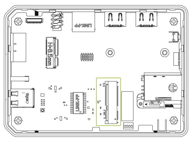
The reComputer AI Industrial R2135 includes a Mini PCIe slot designed primarily for 4G LTE modem modules (e.g., Quectel EC20/EC25).
● Supports: Standard Mini PCIe modules
● Signal interfaces: USB 2.0, UART, SIM card, RESET, etc
● SIM card is routed to onboard SIM card socket
● Control signals: W_DISABLE, PERST, WAKE supported
● Integrated ESD protection for enhanced reliability
| Slot | Supported Protocol |
|---|---|
| Mini-PCIe | 4G LTE |
| USB LoRa® | |
| USB Zigbee |
Reset Hole

There is a Mini Push Button Switch located in the reset hole of the reComputer AI Industrial R2135. By pressing this button with a thin object, the CM4 can be reset. This pin when high signals that the CM4 has started. Driving this pin low resets the module.
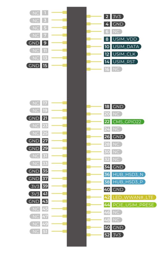
Ethernet RJ45
| Name | Type | Speeds | PoE |
|---|---|---|---|
| ETH0 | CM5 native Gigabit Ethernet | 10/100/1000 Mbit/s | Not Supported |
reComputer AI Industrial R2135 comes with a standard RJ45 Gigabit Ethernet port (GbE), using a MagJack integrated transformer for better signal quality and EMI protection.
● Interface standard: IEEE 802.3 10/100/1000Mbps; ● Uses a Gigabit PHY with 4 differential pairs (TX/RX); ● Supports auto-negotiation and full-duplex communication; ● Includes common mode chokes, ESD protection, and isolation capacitors; ● Onboard green/yellow LEDs indicate link and activity status.
HDMI
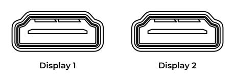
reComputer AI Industrial R2135 comes with two standard HDMI Type-A ports, labeled HDMI0 and HDMI1, which support high-resolution video output. The system is capable of delivering display resolutions up to 4K at 60Hz and supports simultaneous dual HDMI output, making it suitable for multi-display applications.
RTC
reComputer AI Industrial R2135 includes an onboard RTC (PCF8563T) to maintain time across power cycles, enabling it to maintain timekeeping functionality even in the event of power loss.
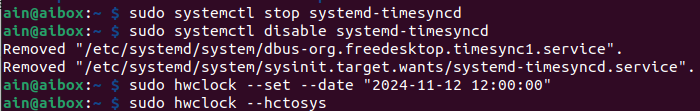
You can test RTC part with command below:
# 1.Disable automatic time synchronization:
sudo systemctl stop systemd-timesyncd
sudo systemctl disable systemd-timesyncd
# Set the time :
sudo hwclock --set --date "2024-11-12 12:00:00"
# Synchronize the RTC time to the system:
sudo hwclock --hctosys
Then you can power off the R2000 for a few minutes, power it back on, and recheck the clock using the following command:
# 4.Check the RTC time:
sudo hwclock -r
The result shows that the RTC module continues to function even when the system is powered off.

Watchdog
reComputer AI Industrial R2135 comes equipped with an independent hardware watchdog circuit that ensures automatic system reboot in case of abnormal system crashes. The watchdog circuit is implemented through RTC and allows for flexible feeding times from 1 to 255 seconds.
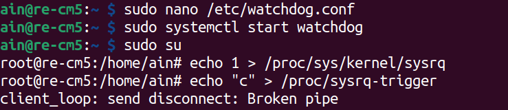
You can test watchdog part with command below:
# 1.Install the watchdog software:
sudo apt install watchdog
# 2. Edit the watchdog configuration file:
sudo nano /etc/watchdog.conf
Then modify the configuration as follows:
watchdog.conf
watchdog-device= /dev/watchdog
# Uncomment and edit this line for hardware timeout values that differ
# from the default of one minute.
watchdog-timeout = 120
# If your watchdog trips by itself when the first timeout interval
# elapses then try uncommenting the line below and changing the
# value to 'yes'.
#watchdog-refresh-use-settimeout = auto
# If you have a buggy watchdog device (e.g. some IPMI implementations)
# try uncommenting this line and setting it to 'yes'.
#watchdog-refresh-ignore-errors = no
# ====================== Other system settings ========================
#
# Interval between tests. Should be a couple of seconds shorter than
# the hardware time-out value.
interval= 15
max-load-1= 24
#max-load-5= 18
#max-load-15= 12
realtime= yes
priority= 1
# 3.Ensure the watchdog service is running:
sudo systemctl start watchdog
# This command triggers a kernel crash and should cause the watchdog to reboot the system.
sudo su
echo 1 > /proc/sys/kernel/sysrq
echo "c" > /proc/sysrq-trigger
As shown in the figure below, the SSH connection was lost after entering the command, indicating that the watchdog has taken effect and rebooted the reComputer AI Industrial R2135.
M.2 AI Acceleration
The reComputer AI Industrial R2135 includes a Hailo-8 AI accelerator module, pre-installed in the NVMe2 M.2 slot, delivering 26 TOPS of computing power for real-time multi-channel AI vision processing.
You can test watchdog part with command below:
Note: To test this feature, a screen needs to be connected to the reComputer AI Industrial R2135.
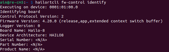
#Test whether the Hailo hardware and its accompanying software have been successfully installed
hailortcli fw-control identify
# Verify whether the pre-installed demo is functional.
cd hailo-rpi5-examples
# Install necessary resources
./install.sh
# Activate the python environment
source setup_env.sh
# Run object detection
python basic_pipelines/detection_simple.py
The result is shown as below:

Optional Interfaces and Module
The reComputer AI Industrial R2135 supports a rich selection of expansion modules and accessories, making it suitable for a wide range of scenarios and requirements. If you are interested in customizing the reComputer AI Industrial R2135, please contact [email protected] for more information. Here is the accessories and optional modules list:
| Remark | Item | Product Name | SKU |
|---|---|---|---|
| These three modules must be used together for LoRaWAN® Function | LoRa® Module | Region optional LoRaWAN Gateway Module (USB) - US915 | 114992629 |
| Region optional LoRaWAN Gateway Module (USB) - US915 | 114992991 | ||
| Region optional LoRaWAN Gateway Module (USB) - EU868 | 114992628 | ||
| This accessory is required for WiFi function | Wi-Fi/BLE Antenna | Raspberry Pi Compute Module 4 Antenna Kit | 114992364 |
| 4G antenna with 4G module for 4G function, GPS antenna with 4G module for GPS function | 4G Module | LTE Cat 4 EC25-AFXGA-mini-PCIe Module - for North America | 113991134 |
| LTE Cat 4 EC25-EUXGR-mini-PCIe Module - for EMEA and Thai | 113991135 | ||
| LTE Cat 4 EC25-AUXGR-mini-PCIe Module - for Australia | 113991174 | ||
| LTE Cat 4 EC25-EFA-mini-PCIe Module - for Thai | 113991214 | ||
| LTE Cat 4 EC25-EMGA-mini-PCIe Module - for Malaysia | 113991234 | ||
| LTE Cat 4 EC25-JFA-mini-PCIe Module | 113991296 | ||
| 4G Antenna | 4G Antenna Kit for 4G module | 110061502 | |
| GPS Antenna | GPS Antenna Kit for EC25 4G Module | 110061521 | |
| Encryption Chip | TPM2.0 Module with Infineon SLB9670 | 114993114 | |
| SSD Card | NVMe M.2 2280 SSD 2TB | 114993467 | |
| NVMe M.2 2280 SSD 1TB | 112990267 | ||
| 512GB NVMe M.2 PCIe Gen3x4 2280 Internal SSD | 112990247 | ||
| 256GB NVMe M.2 PCIe Gen3x4 2280 Internal SSD | 112990246 | ||
| 128GB NVMe M.2 PCIe Gen3x4 2280 Internal SSD | 112990226 |
Wi-Fi/BlueTooth
The reComputer AI Industrial R2135 is powered by the CM5 with an onboard Wi-Fi/BLE version, providing the same Wi-Fi/BLE parameters as the CM5. For detailed parameter information, please refer to the Raspberry Pi official website.
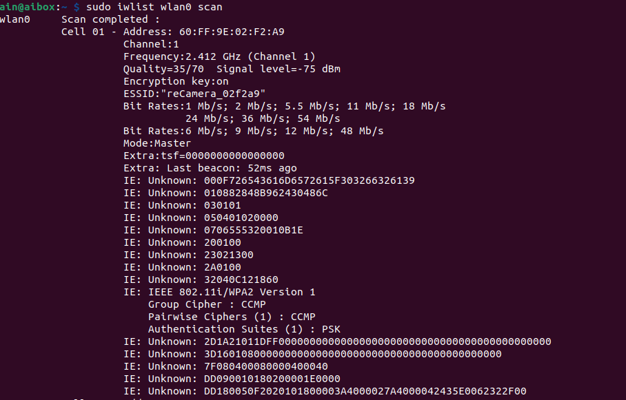
Using command below to test wifi model:
sudo iwlist wlan0 scan
The result is shown in the figure below.
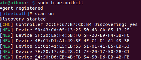
Using command below to test BlueTooth model:
sudo bluetoothctl
scan on
The result is shown in the figure below.
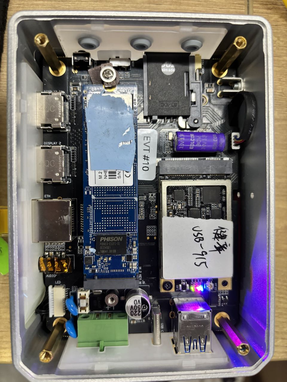
LoRa® USB Module
The Mini-PCIe slots also supports LoRa® module using the USB protocol. The WM1302 module from Seeed Studio has been fully tested to be compatible with the reComputer AI Industrial R2135.
You can test LoRa® USB Module as below:
git clone https://github.com/Lora-net/sx1302_hal
cd sx1302_hal
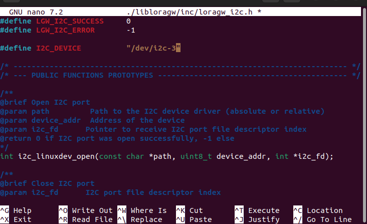
sudo nano ./libloragw/inc/loragw_i2c.h
Change #define I2C_DEVICE "/dev/i2c-1" to #define I2C_DEVICE "/dev/i2c-3".
# compile the code
sudo make
Then modify the configuration code:
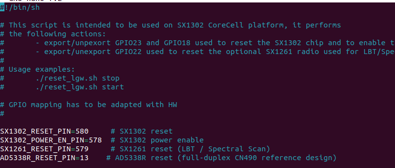
sudo nano ./tools/reset_lgw.sh
Update the pin configurations:
reset_lgw.sh
SX1302_RESET_PIN=580   # SX1302 reset
SX1302_POWER_EN_PIN=578 # SX1302 power enable
SX1261_RESET_PIN=579   # SX1261 reset (LBT / Spectral Scan)
# Copy the reset_lgw.sh script
cp ~/sx1302_hal/tools/reset_lgw.sh ~/sx1302_hal/packet_forwarder/
# Check the device name
ls /dev/spidv10.0
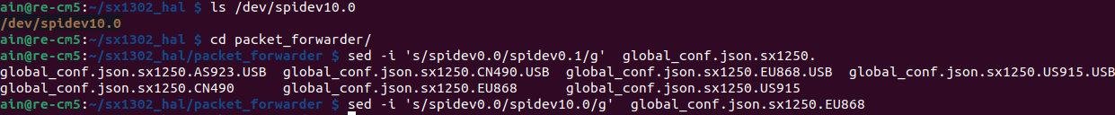
cd ~/sx1302_hal/packet_forwarder
sed -i 's/spidev0.0/spidev10.0/g' global_conf.json.sx1250.US915.USB
echo 1 > /sys/class/gpio/gpio580/value
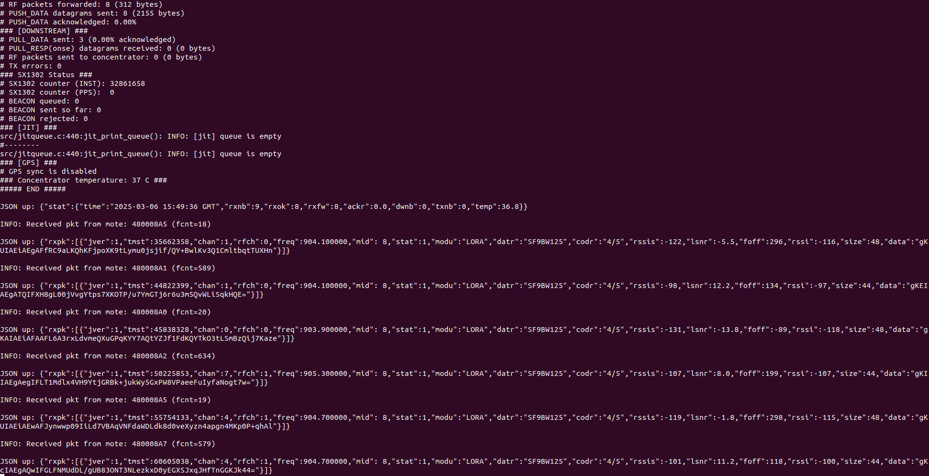
./LoRa_pkt_fwd -c global_conf.json.sx1250.US915.USB
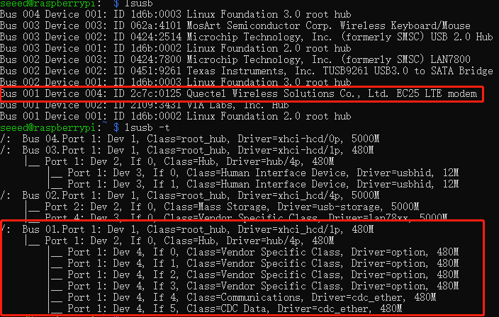
4G Module
The reComputer AI Industrial R2135 mainboard features one Mini-PCIe slots, with Mini-PCIe slot supporting a 4G module using the USB protocol. The EC25 4G module from Quectel has been fully tested to be compatible with the reComputer AI Industrial R2135.
Note: Make sure you have installed 4G Module on the reComputer AI Industrial R2135
Using command below to test 4G model:
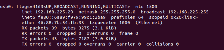
# Check the information of the 4g module
ifconfig
The result is shown in the figure below.
# Check the information of the usb0 ethernet port
ip link show usb0

# Start usb0 ethernet port
sudo ip link set dev usb0 up
# Request an IP address from the DHCP server on the network and assign it to the usb0 interface
sudo dhclient usb0
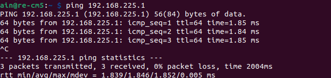
Then test if it can ping default router
ping 192.168.225.1
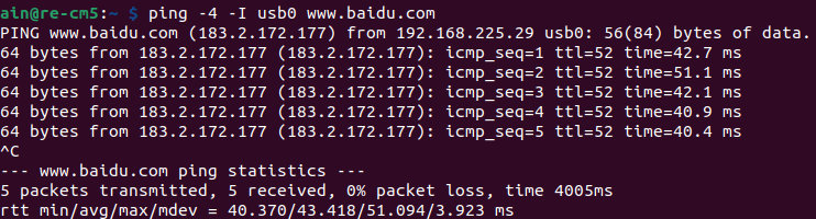
# ping baidu.com use usb0
ping -4 -I usb0 www.baidu.com
TPM 2.0
TPM (Trusted Platform Module) is a hardware chip specifically designed to enhance computer security by providing hardware-based cryptographic functions. It securely stores sensitive data such as encryption keys, certificates, and passwords, and is commonly used in scenarios like secure boot, disk encryption (e.g., BitLocker), and authentication.
Check TPM on reComputer AI Industrial R2135 with command as below:
ls /dev | grep tpm

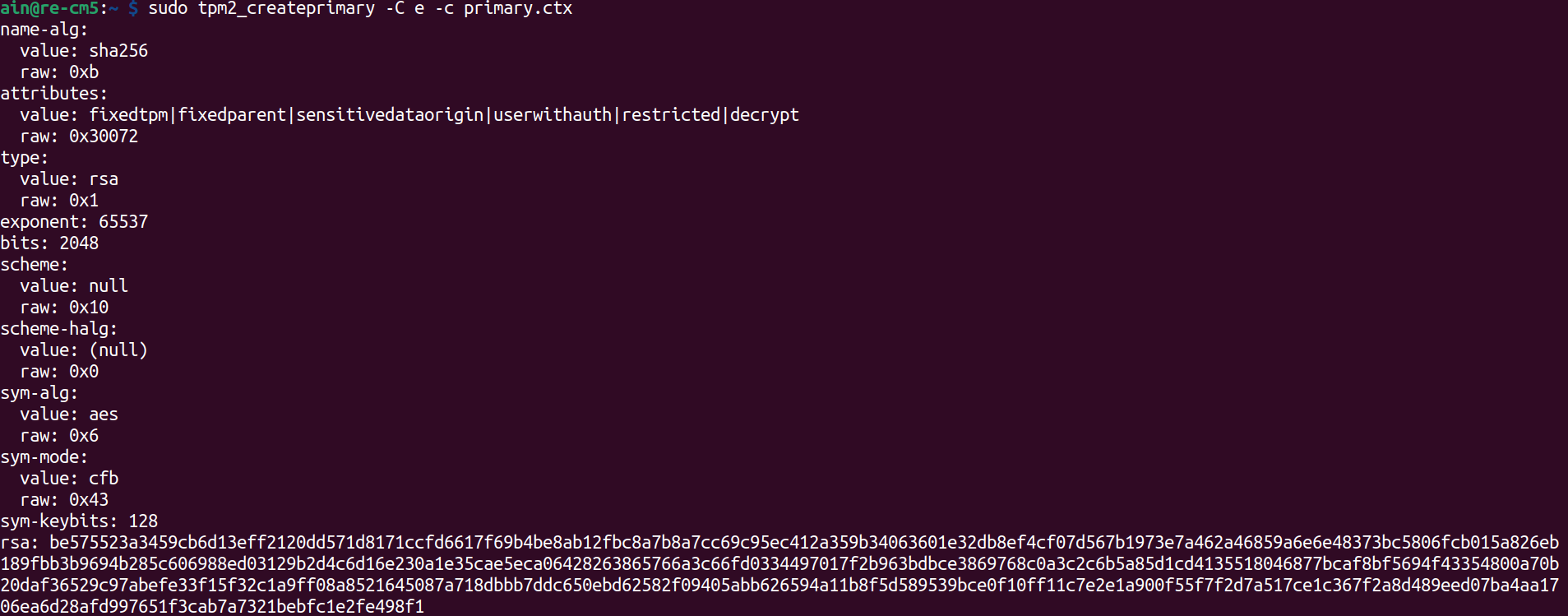
# Test tpm as following:
sudo tpm2_createprimary -C o -c primary.ctx
SSD
The reComputer AI Industrial R2135 supports 2280 NVMe SSD through the use of the NVMe1 PCIe slot(J8).
Note
There are two main uses for SSD cards:
- High Capacity Storage: SSD cards can be utilized for high-capacity storage needs.
- Boot Drive with Image: SSD cards can serve both as high-capacity storage and as a boot drive by storing system images, allowing direct boot from the card.
It’s important to note that not all SSD cards on the market support boot functionality. If you plan to use an SSD as a boot drive and are unsure which model to choose, we recommend our tested 1 TB SSD (SKU 112990267). This model has been verified for boot functionality, reducing compatibility risks and minimizing trial-and-error costs.
You can check ssd use command below:
sudo fdisk -l | grep sda

Application
Frigate
Frigate is an open-source NVR (Network Video Recorder) designed for real-time object detection using AI. It integrates with existing cameras and uses machine learning models, like TensorFlow and Coral, to perform object detection on video feeds. Frigate is optimized for low-latency and high-performance video processing, offering features like motion detection, live video streams, and automated alerts.
Note: If you want to learn more about this project, please refer to this link.
YOLO
The YOLO (You Only Look Once) series of models are a family of real-time object detection models designed for speed and accuracy. Unlike traditional object detection methods that perform region proposal and classification separately, YOLO performs both tasks in a single forward pass of the neural network, making it much faster. YOLO models divide the image into a grid and predict bounding boxes and class probabilities for each grid cell. Over the years, YOLO has evolved through various versions, with improvements in accuracy, speed, and the ability to detect smaller objects. YOLOv4, YOLOv5, and the recent YOLOv7 and YOLOv8 models are widely used for applications like surveillance, autonomous vehicles, and robotics.
Note: If you want to learn more about this project, please refer to this link.
Clip
CLIP (Contrastive Language-Image Pretraining) is a machine learning model developed by OpenAI that can understand images and text together. It is trained to associate images with corresponding textual descriptions, allowing it to perform tasks that involve both modalities. CLIP is capable of zero-shot learning, meaning it can recognize objects and concepts in images without needing to be specifically trained on those categories. It has shown strong performance in a variety of tasks, such as image classification, object detection, and even generating textual descriptions of images.
Note: If you want to learn more about this project, please refer to this link.
Tech Support & Product Discussion
Thank you for choosing our products! We are here to provide you with different support to ensure that your experience with our products is as smooth as possible. We offer several communication channels to cater to different preferences and needs.