reComputer Industrial R20xx Assembly Guide

The reComputer Industrial R20xx supports a variety of IoT wireless communications, including 4G, 5G, LoRa®, Wi-Fi/BLE, and Zigbee. It supports expansion via an M.2 slot for SSD storage or AI capabilities via an NPU accelerator. If you choose to include the AI accelerator directly in your purchase, you'll gain an additional 26TOPS of computing power. Furthermore, our hardware engineering services include logo customization, package branding, labeling, firmware flashing, and imaging services, providing comprehensive support tailored to your specific needs.
This Wiki will show you how to Assemble and Disassemble the unit to install peripherals components, as well as the option for mounting
Hardware Prerequisites
You need to prepare the following hardware
- reComputer Industrial R20xx x 1
- Accessories
- Screw Driver set
- Phillips + 3.5 bit
- Phillips + 3.0 bit
- Slotted - 2.5 bit
Device Disassembly Guide
Following these steps should help you disassemble the device without any issues.
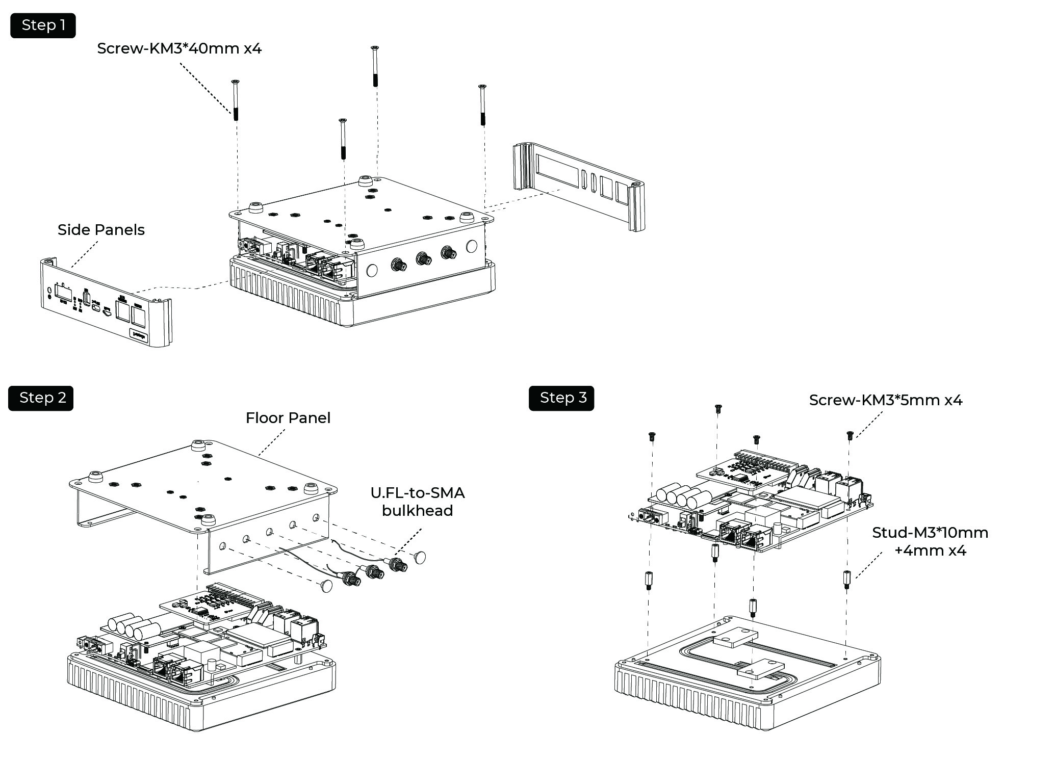
Step 1: Remove the Four Screws at the Bottom and remove the front and rear panels:
- Locate and unscrew the four screws located at the bottom of the device using an appropriate screwdriver.
- Once the screws are removed, carefully lift off the front and rear panels from the device.
Step 2: Unscrew the side antenna connector nuts and remove the Floor Panel.
Step 3: Remove the four screws that secure the PCB in place
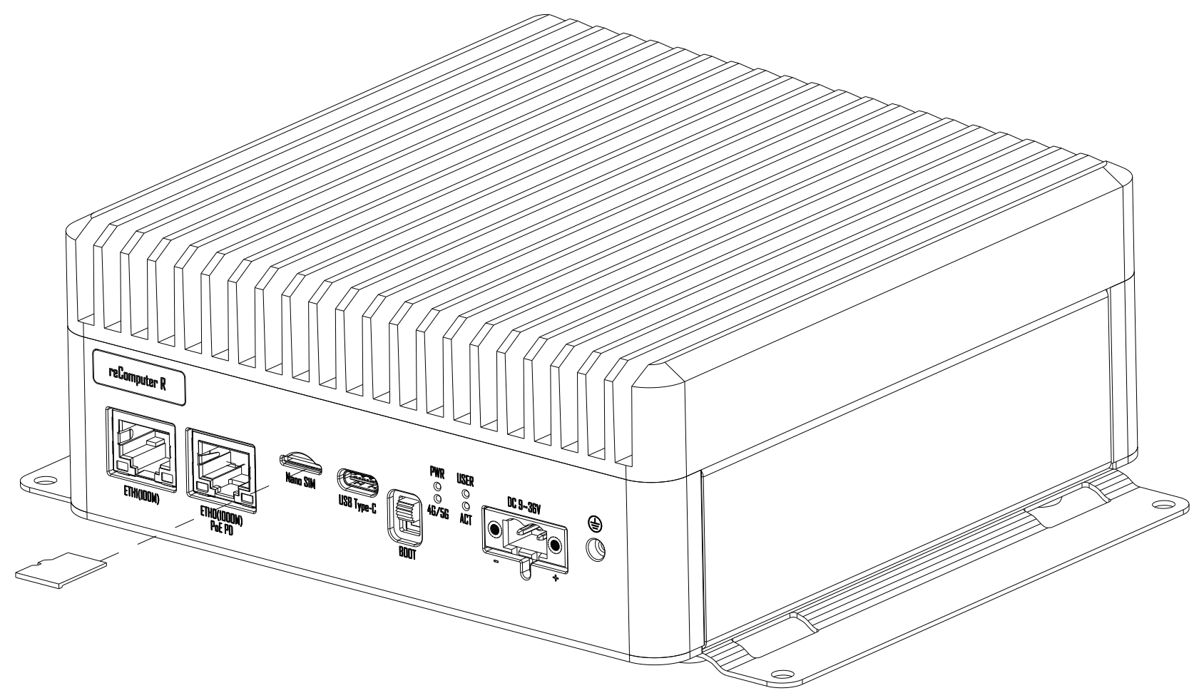
Installing a Nano SIM Card
Step 1: Load the Nano SIM Card into the SIM slot.
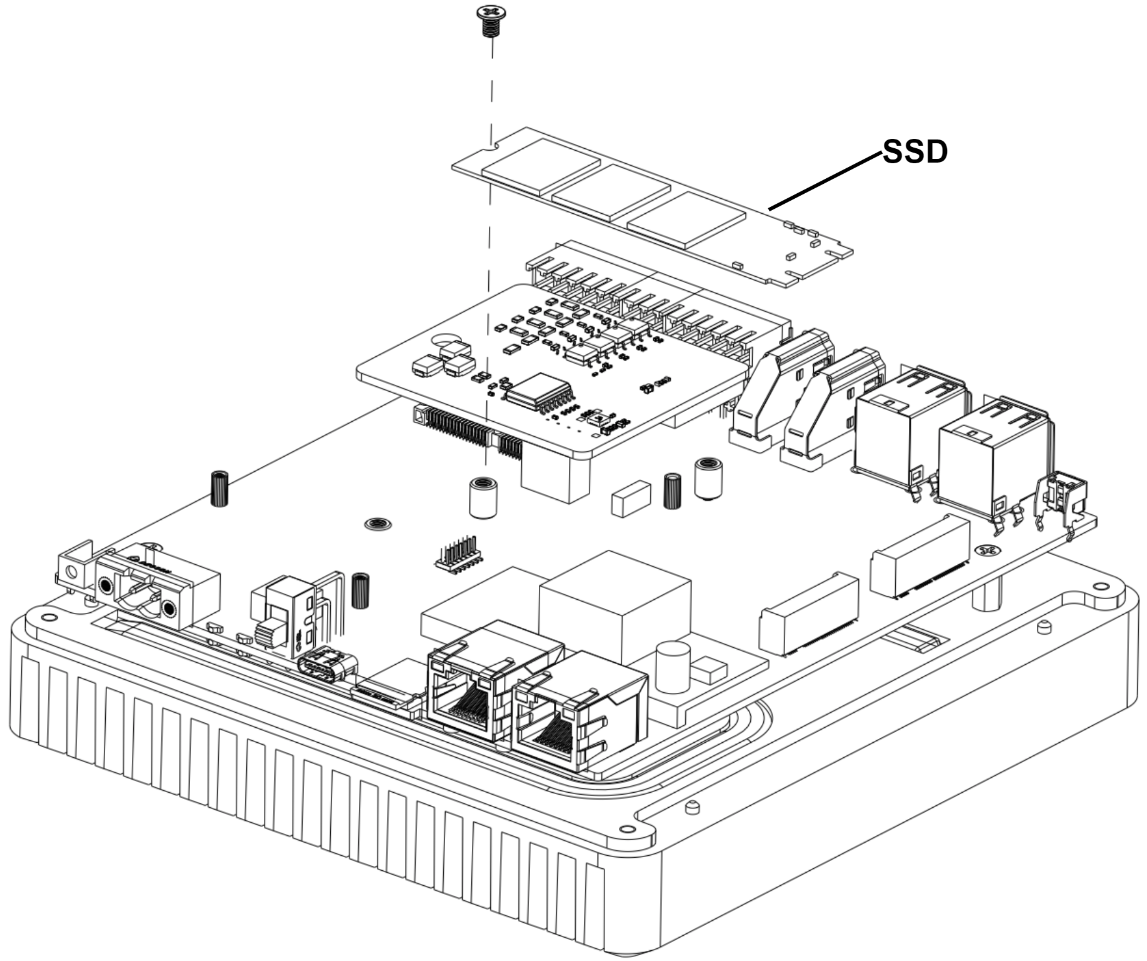
Installing an SSD
Step 1: Remove the back cover following the disassembly guide.
Step 2: Load the SSD into the M.2 socket and lock the screws.
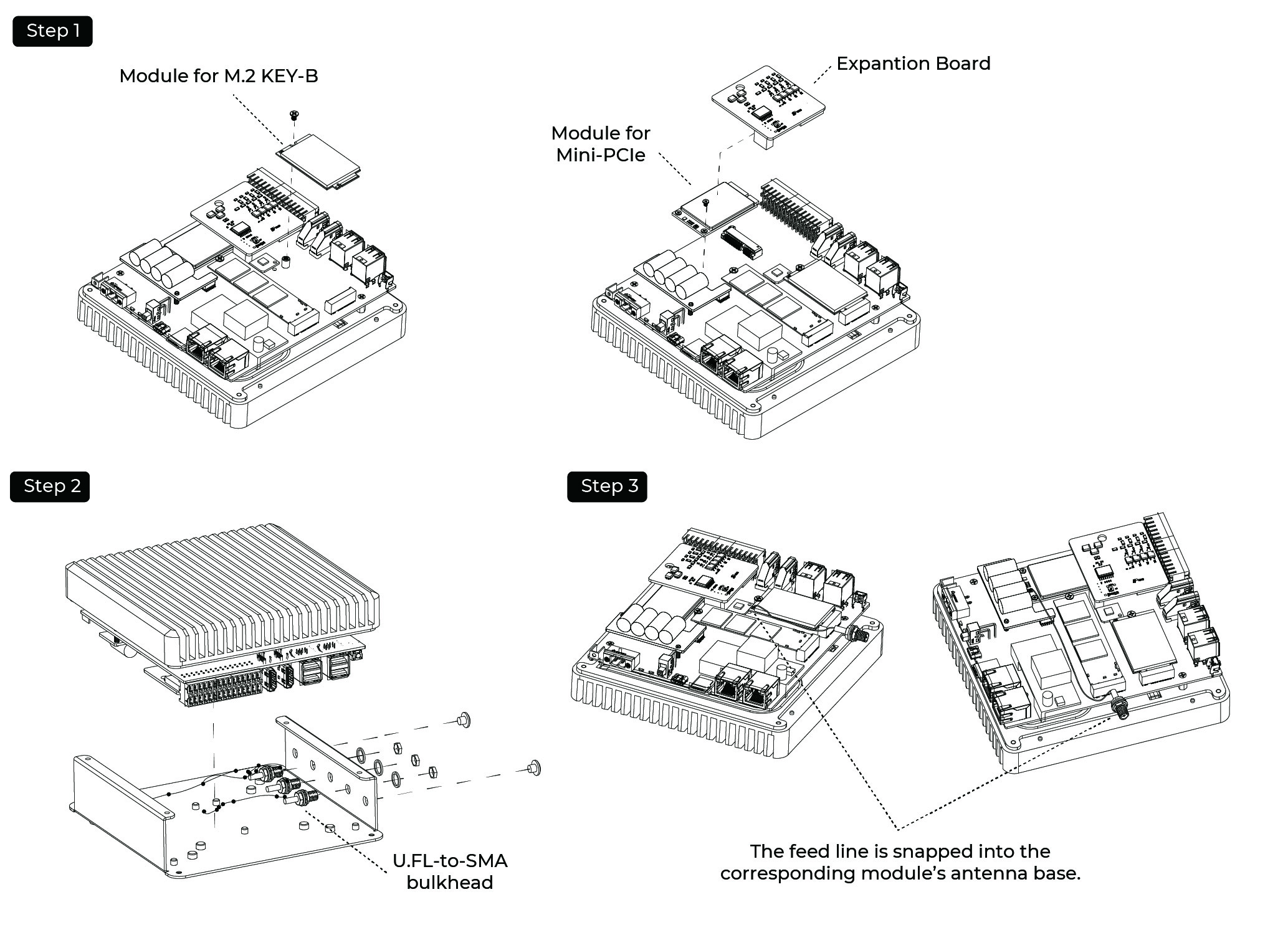
Assembling 5G/4G/LoRa®/Zigbee Module and Antenna
Step 1: Remove the Expantion Board and load the 4G module/LoRa® Module/Zigbee Module into the Mini-PCIe/M.2 B-KEY slot and lock the screws.
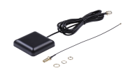
Step 2: Connect the feeder to the antenna hole on the housing as shown in the following diagram.
Step 3: Install the feeder into the antenna base of the corresponding module.
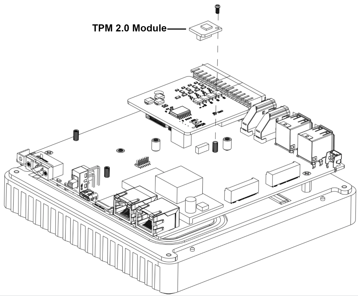
Assembling the TPM 2.0 Module
Step 1: Remove the back cover following the disassembly guide.
Step 2: Load the TPM 2.0 module into the J26 socket.
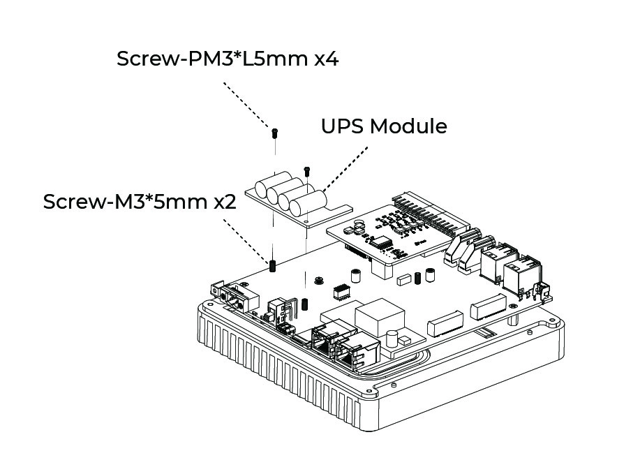
Assembling the UPS and PoE Module
Step 1: Before installing the UPS and PoE module on the CM5 module side of board, disassemble the entire device following the disassembly guide provided.
Step 2: Install the UPS Module**
- Using two PM2.0xL5.0 screws and M2.0x5.0 standoffs, secure the UPS module onto two holes without metal contact pads.
- Make sure the UPS module is aligned properly and firmly attached using the provided screws and standoffs.
Step 3: Install the PoE Module
- Align the PoE module with the designated slot on the board.
- Carefully solder the PoE module onto the board, ensuring precision to prevent damage to nearby components.
Mounting Guide
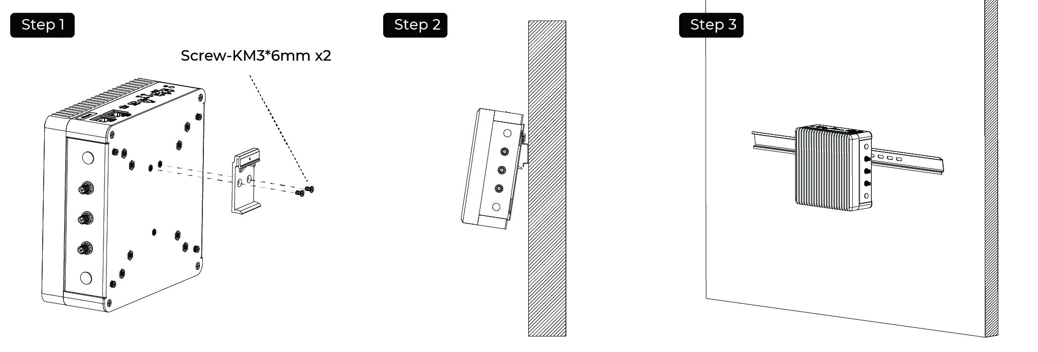
DIN-Rail Mounting Guide
reComputer Industrial R20xx offers various installation methods. The DIN-rail clip and installation screws are included in the packaging. Follow the diagram to correctly attach the DIN-rail clip to the mounting holes on the side of the device. Once the screws are securely fastened, you can then install the device onto the mounting rail.
Installation Steps
- Step 1: Place the device and rail clip on the upper edge of the standard profile rail at the position shown and push the device down.
- Step 2: Swing the rail clip of the device from below through the standard profile rail.
- Step 3: Push the device in the direction of the standard profile rail. You will hear the device click into place.
Removal Steps
- Step 1: Push down the device until it is released by the rail clip.
- Step 2: Swing the device out of the standard profile rail.
- Step 3: Lift the device up and of
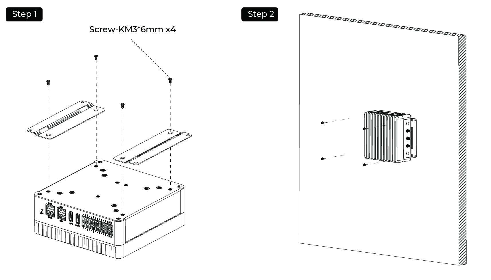
Wall Mounting Guide
Vertical mounting method is also suitable for reComputer Industrial R20xx, however the mounting brackets are not included in box, that need additional purchase.
Installation Steps
- Step 1: Lay the mounting brackets on the rear of the device.
- Step 2: Fasten the brackets with supplied screws.
- Step 3: Mark the bore holes, drill the required holes in the wall and fasten the device to the wall using two screws.
Accessories List


Tech Support & Product Discussion
Thank you for choosing our products! We are here to provide you with different support to ensure that your experience with our products is as smooth as possible. We offer several communication channels to cater to different preferences and needs.