Configure reComputer Industrial R22xx
Overview
Learn how to configure and test hardware components on the reComputer Industrial R22xx series after installing devices. This wiki covers GPIO mapping, USER LED testing, SPI communication, Wi-Fi and Bluetooth scanning, LoRa®, 4G, 5G,Zigbee over Mini-PCIe, RS485, RS232, CAN,DI/DO testing, UPS for safe shutdown and more.

Query GPIO Mappings and Offsets
To query GPIO mappings and offsets, follow these steps:
- Copy and paste the following command to query GPIO mappings:
cat /sys/kernel/debug/gpio
This command will display GPIO mappings and offsets, providing essential information for debugging or configuring GPIO pins.
USER LED Testing
We provide LEDs in three colors of red, blue and green for users to use. You can enter the /sys/class/leds/ directory to view:
1. Navigate to the LED directory
cd /sys/class/leds/
ls

Use the following command to light up the LED of the corresponding color.
sudo su
echo 1 > /sys/class/leds/led-red//brightness
echo 1 > /sys/class/leds/led-blue/brightness
echo 1 > /sys/class/leds/led-green/brightness
This will light up the corresponding LED.
3. Turn off LEDs (optional)
To turn off a specific LED, use:
sudo su
echo 0 > /sys/class/leds/led-red/brightness
echo 0 > /sys/class/leds/led-blue/brightness
echo 0 > /sys/class/leds/led-green/brightness
Testing SPI Communication
To test SPI communication by shorting the TPM module's MISO and MOSI pins, follow these steps:
- Clone the spidev-test repository:
# Don't forget to connect to network before running command
git clone https://github.com/rm-hull/spidev-test.git
- Navigate into the spidev-test directory:
cd spidev-test
- Compile the spidev_test.c file:
gcc spidev_test.c -o spidev_test
- Run the spidev_test program with the following command:
./spidev_test -D /dev/spidev10.0 -v -p hello
This command tests SPI communication on the specified SPI device (/dev/spidev10.0) with verbose output ( -v ) and sends the message "hello" (-p hello). By shorting the TPM module's MISO and MOSI pins, you're effectively creating a loopback scenario, where data sent on MOSI is received on MISO. This setup allows you to test SPI communication without an actual device connected.
Wi-Fi Scanning
To list available Wi-Fi networks and their details, run:
sudo iwlist wlan0 scan
- This command scans for all nearby Wi-Fi networks and displays their SSIDs, signal strength, and encryption type.
Bluetooth Scanning
To scan for Bluetooth devices, follow these steps:
Open the Bluetooth control interface:
sudo bluetoothctl
This command will open the Bluetooth control interface. From there, you can run additional commands to scan for nearby Bluetooth devices.
Enable scanning:
scan on
This command will start scanning for nearby Bluetooth devices. You can then use other commands within the bluetoothctl interface to interact with Bluetooth devices, such as pairing or connecting to them.
LoRa® over Mini-PCIe
LoRa® SPI Configuration
After install the LoRa® SPI to Mini-PCIe slot 2, can configure LoRa® SPI, follow these steps:
- Clone the SX1302_HAL repository:
cd ~/
git clone https://github.com/Lora-net/sx1302_hal
- Navigate to the cloned directory:
cd sx1302_hal
- Modify the configuration file:
Open the I2C device configuration file:
sudo nano ./libloragw/inc/loragw_i2c.h
Change this line:
#define I2C_DEVICE "/dev/i2c-1"
To:
#define I2C_DEVICE "/dev/i2c-2"
Change #define I2C_DEVICE "/dev/i2c-1" to #define I2C_DEVICE "/dev/i2c-2". Press ctrl+x to exit, press y to save changes, and then press Enter to return to the command line page.
- 4.Add the packet_forwarder/reset_lgw.sh file:
sudo nano packet_forwarder/reset_lgw.sh
Add the execution code:
SX1302_RESET_PIN=632     # SX1302 reset
SX1302_POWER_EN_PIN=633  # SX1302 power enable
SX1261_RESET_PIN=634     # SX1261 reset (LBT / Spectral Scan)
# AD5338R_RESET_PIN=13    # AD5338R reset (full-duplex CN490 reference design)
The firmware natively supports the SPI model WM1302-SPI-US915-M. If you wish to use other models, you can query the definition of the corresponding RESET_PIN and modify the RESET_PIN by referring to the following commands.
cat /sys/kernel/debug/gpio
Press ctrl+x to exit, press y to save changes, and then press Enter to return to the command line page.
- Modify the configuration code:
cp ./tools/reset_lgw.sh ./packet_forwarder
- Comment out lines 18, 29, 35, 42, 53, and 54 respectively:
nano ./packet_forwarder/global_conf.json.sx1250.US915
Change "com_path": "/dev/spidev0.0" to "com_path": "/dev/spidev2.0".
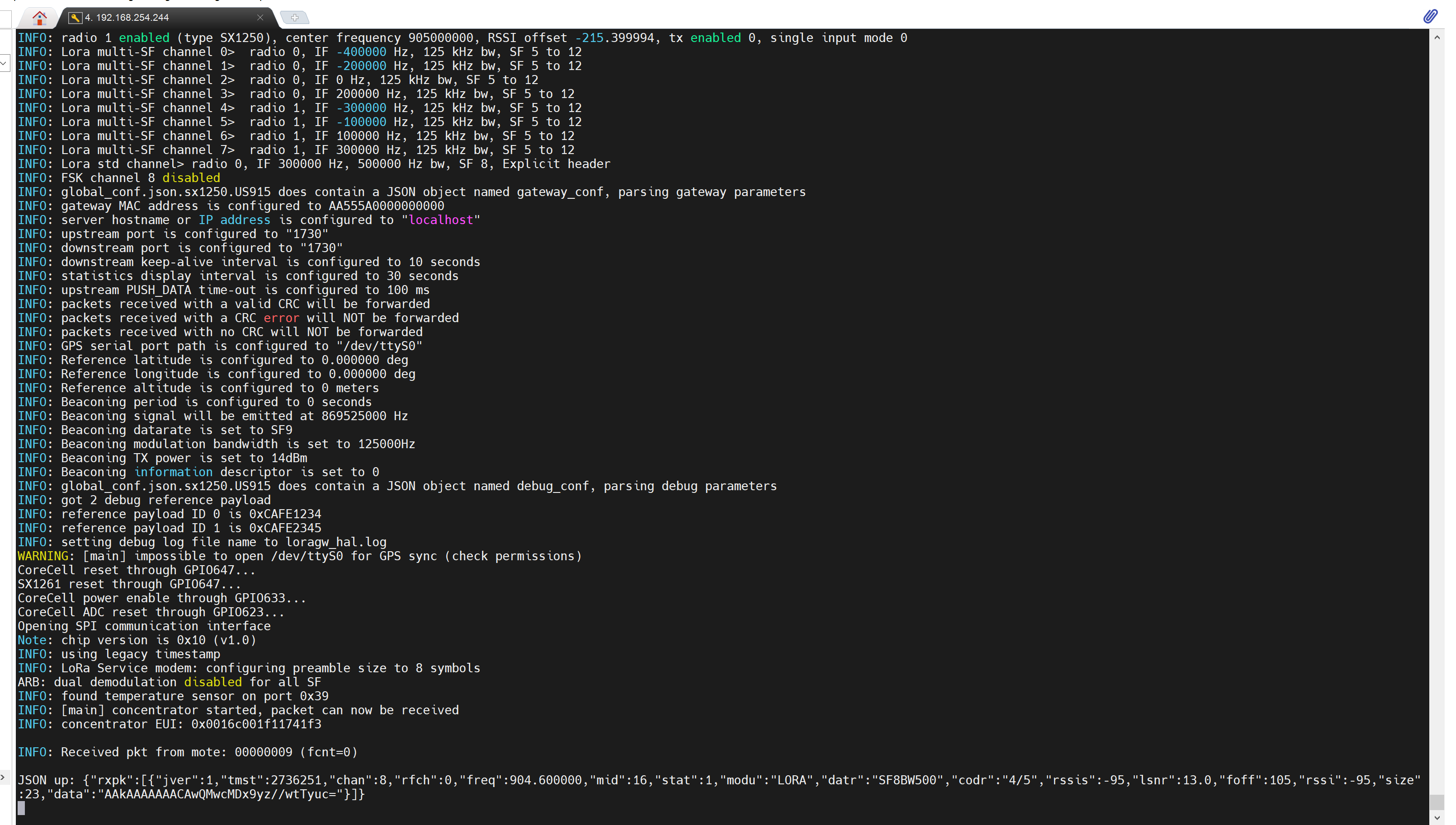
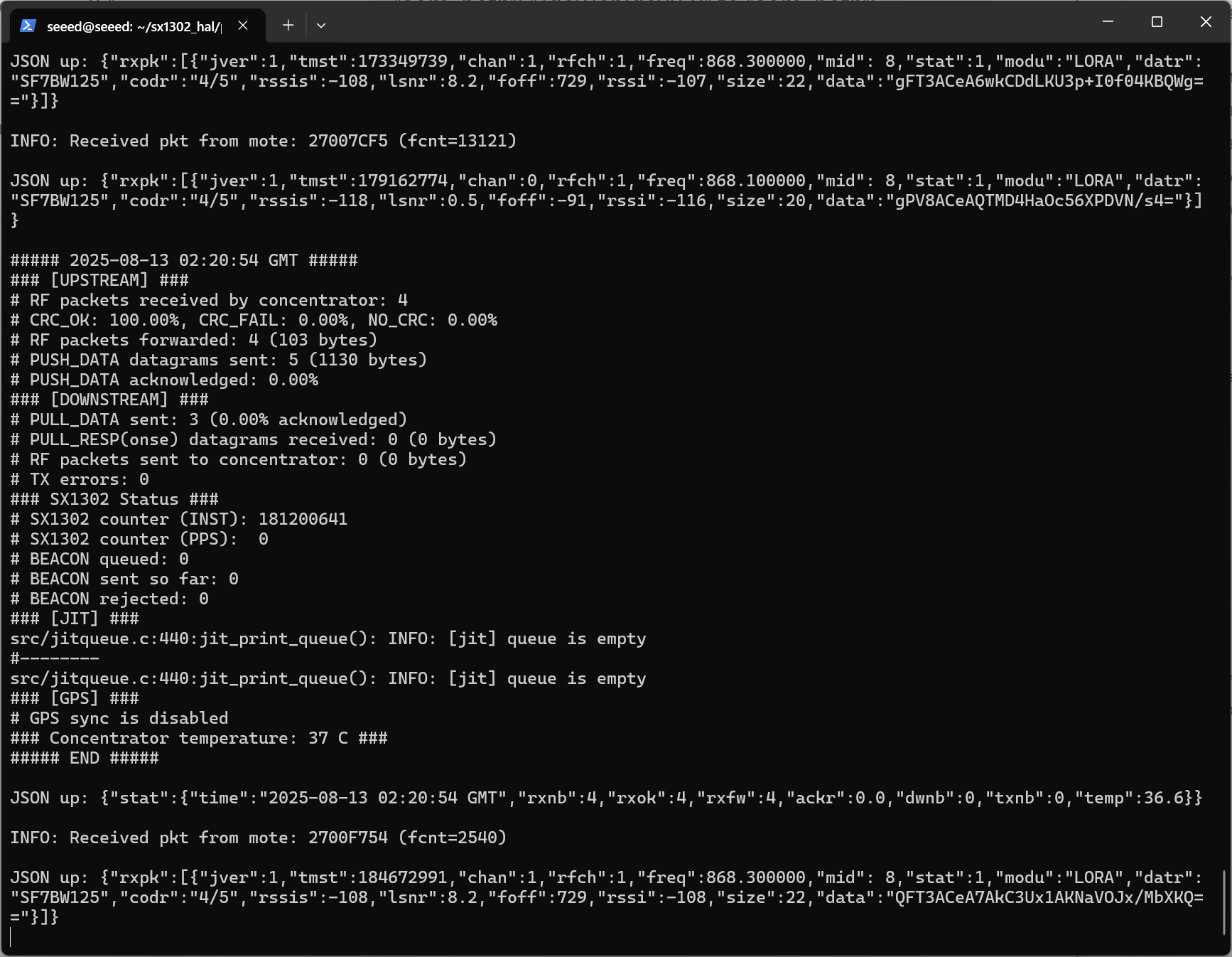
 cd ./packet_forwarder
sudo ./lora_pkt_fwd -c global_conf.json.sx1250.US915
LoRa® USB Configuration
For LoRa® USB, the previous commands remain the same as for LoRa® SPI. However, the final command needs to be changed to:
cho  632  >  /sys/class/gpio/export
echo  "out"  >  /sys/class/gpio/gpio632/direction
echo  "1"  >  /sys/class/gpio/gpio632/value

sudo  ./lora_pkt_fwd  -c  global_conf.json.sx1250.EU868.USB
This command specifies the configuration file to be used for LoRa® USB.
5G Cellular over M.2 B-KEY
To interact with a 5G/4G module using AT commands via minicom, follow these steps:
- Create a new power_5g.sh file:
nano power_5g.sh
Open with sudo nano and enter the following command, then press ctrl+x to save and exit.
#!/bin/bash

RESET_PIN=655
POWER_PIN=660

if [ ! -d "/sys/class/gpio/gpio$RESET_PIN" ]; then
    echo $RESET_PIN > /sys/class/gpio/export
fi

if [ ! -d "/sys/class/gpio/gpio$POWER_PIN" ]; then
    echo $POWER_PIN > /sys/class/gpio/export
fi

echo "out" > /sys/class/gpio/gpio$RESET_PIN/direction
echo "out" > /sys/class/gpio/gpio$POWER_PIN/direction

echo 1 > /sys/class/gpio/gpio$RESET_PIN/value
echo 1 > /sys/class/gpio/gpio$POWER_PIN/value

echo "Start to reboot 5g module"

echo 0 > /sys/class/gpio/gpio$RESET_PIN/value
sleep 0.05
echo 0 > /sys/class/gpio/gpio$POWER_PIN/value

echo "5g module reboot completed"
- Execute the file:
sudo ./power_5g.sh
After 10-15 seconds (it takes a while for the module to power on and enumerate USB), check whether the device node appears:
ls /dev/ttyUSB*
Output /dev/ttyUSB0, etc.:

Open minicom with the appropriate serial port and baud rate:
sudo apt update
sudo apt install minicom
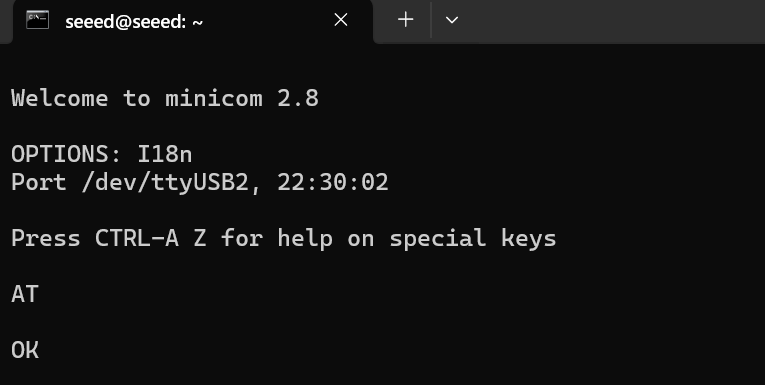
sudo minicom -D /dev/ttyUSB2 -b 115200
This command opens minicom with the specified serial port (/dev/ttyUSB2) at a baud rate of 115200.
- Once minicom is open, you can start sending AT commands to the 4G module. For example:
AT
This command checks if the module is responsive. You should receive an "OK" response if the module is working properly.
- To dial a phone number using the 4G module, you can use the ATD command followed by the phone number:
ATD<phone_number>;
Replace phone_number with the desired phone number you want to dial. Make sure to include a semicolon ; at the end of the command to indicate the end of the phone number.
4G Cellular over Mini-PCIe
Create a new power_4g.sh file:
sudo nano power_4g.sh
Open with sudo nano and enter the following command, then press ctrl+x to save and exit.
# SIM_MUX_SEL
echo 655 > /sys/class/gpio/export
echo out > /sys/class/gpio/gpio655/direction
echo 0 > /sys/class/gpio/gpio655/value
echo 660 > /sys/class/gpio/export
echo out > /sys/class/gpio/gpio660/direction
echo 1 > /sys/class/gpio/gpio660/value
Execute the file:
sudo ./power_4g.sh
Enter minicom to send commands:
sudo apt install minicom -y
sudo minicom -D /dev/ttyUSB2 -b 115200
Press Ctrl+A, Z , E in sequence. First send AT to test whether it is connected. If OK appears, the connection is successful.
After executing the following command, the module will automatically restart. If you do not exit minicom, you can see the corresponding configuration information. ECM Dial-up Internet Access:
AT+QCFG="usbnet",1
Until the last line shows OK, it will be successful.
Note The device needs to wait for a while, and then you can view the ip address of usb0 in ifconfig.
Test network status and communication:
# Check network status
ifconfig
# Test communication
ping www.baidu.com -I usb0
Zigbee over Mini-PCIe
To test Zigbee communication between two Zigbee modules, follow these steps:
- Check Available Serial Ports
Use the following command to check available serial ports:
cat /dev/ttyUSB*
Install a Serial Communication Tool
- Install Serial Communication Tool:
sudo apt-get install cutecom
- Open Serial Port for Coordinator (First Zigbee Module):
- Open the cutecom tool and configure it for the first serial port:
- Baud rate: 115200
- Check the "Hex output" option at the bottom of the interface.
- Follow these steps to configure the first Zigbee module:
- Set as coordinator: Send command ‘55 04 00 05 00 05’, expect response ‘55 04 00 05 00 05’.
- Reset device: Press reset button or send command ‘55 07 00 04 00 FF FF 00 04’.
- Network formation: Send command ‘55 03 00 02 02’.
- Open Serial Port for Router (Second Zigbee Module): Open another instance of cutecom and configure it for the second serial port with the same settings as before. Follow these steps to configure the second Zigbee module:
- Set as router: Send command ‘55 04 00 05 01 04’, expect response ‘55 04 00 05 00 05’.
- Reset device: Press reset button or send command ‘55 07 00 04 00 FF FF 00 04’.
- Network formation: Send command ‘55 03 00 02 02’.
- Check Device Status: Send command ‘55 03 00 00 00’ to check the device status. Expect a response similar to ‘55 2a 00 00 00 01 XX XX XX XX’, where ‘XX’ represents device information.
- Enter Transparent Mode: If network formation is successful, enter transparent mode by sending command 55 07 00 11 00 03 00 01 13. Both modules should be in transparent mode for direct communication. To exit transparent mode, send "+++".
- Additional Notes:
- If router configuration fails, the device may already be a coordinator. Leave the network using command '55 07 00 04 02 xx xx xx'.
- Test transmission power using commands '55 04 0D 00 00 0D' (query) and '55 04 0D 01 XX XX' (set). Ensure you replace /dev/ttyUSB with the correct serial port for each Zigbee module. Follow these steps carefully to test Zigbee communication between the two modules successfully.
RS485 Testing
The reComputer Industrial R21xx includes 2x RS485 ports. Below are their corresponding COM ports and device files:
| Number of RS485 Ports | COM Port | Silkscreen Label | Device File |
|---|---|---|---|
| RS485-2 | COM2 | A2/B2/GND3 | /dev/ttyACM1 |
| RS485-3 | COM3 | A3/B3/GND4 | /dev/ttyACM2 |
To test the RS485 function, you can follow the steps below (take RS485_1 and RS485_2 as examples):
- Please connect RS485_1 and RS485_2's A and B.
- Open minicom in two terminal windows respectively:
sudo minicom -D /dev/ttyACM1
sudo minicom -D /dev/ttyACM2
If there is an expansion board, the number needs to be moved back one place, for example /dev/ttyAcM2, /dev/ttyAcM3.
- The following operations need to be performed on both opened ACMs:
-
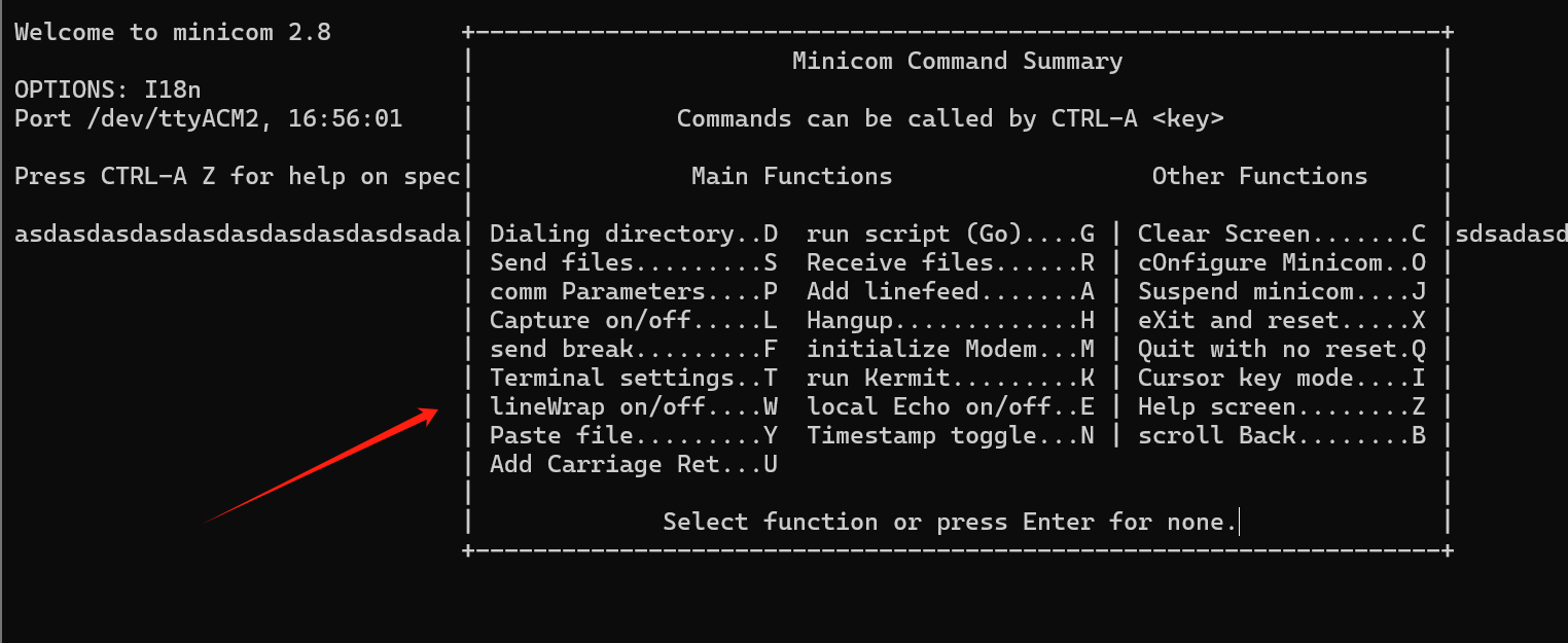
Press Ctrl+A, then press Z, and the Minicom Command Summary interface will appear:
-
Press O again to open configuration, select Serial port setup, and press Enter; Open all RS485 related interfaces, press H/I/J/K/L in sequence to open;
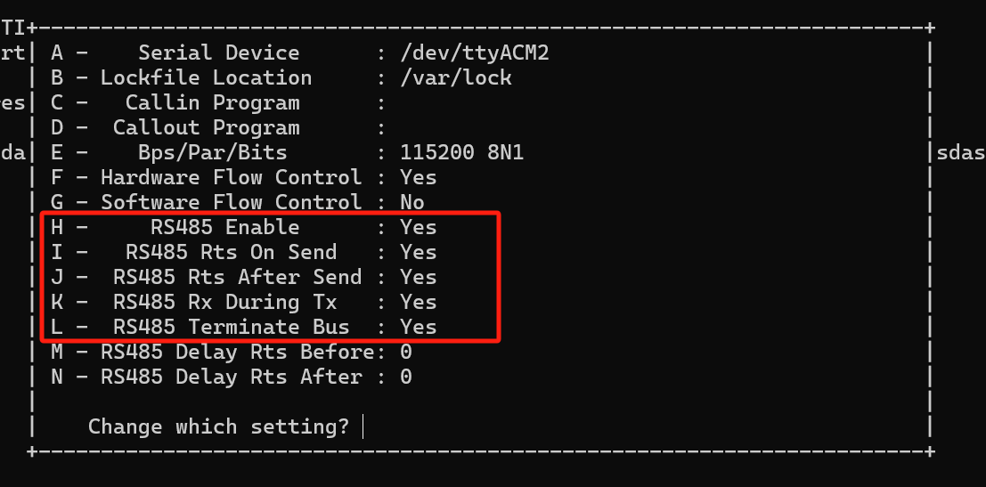
-
After all "YES" are displayed, press Enter to return, and then select Exit to exit.
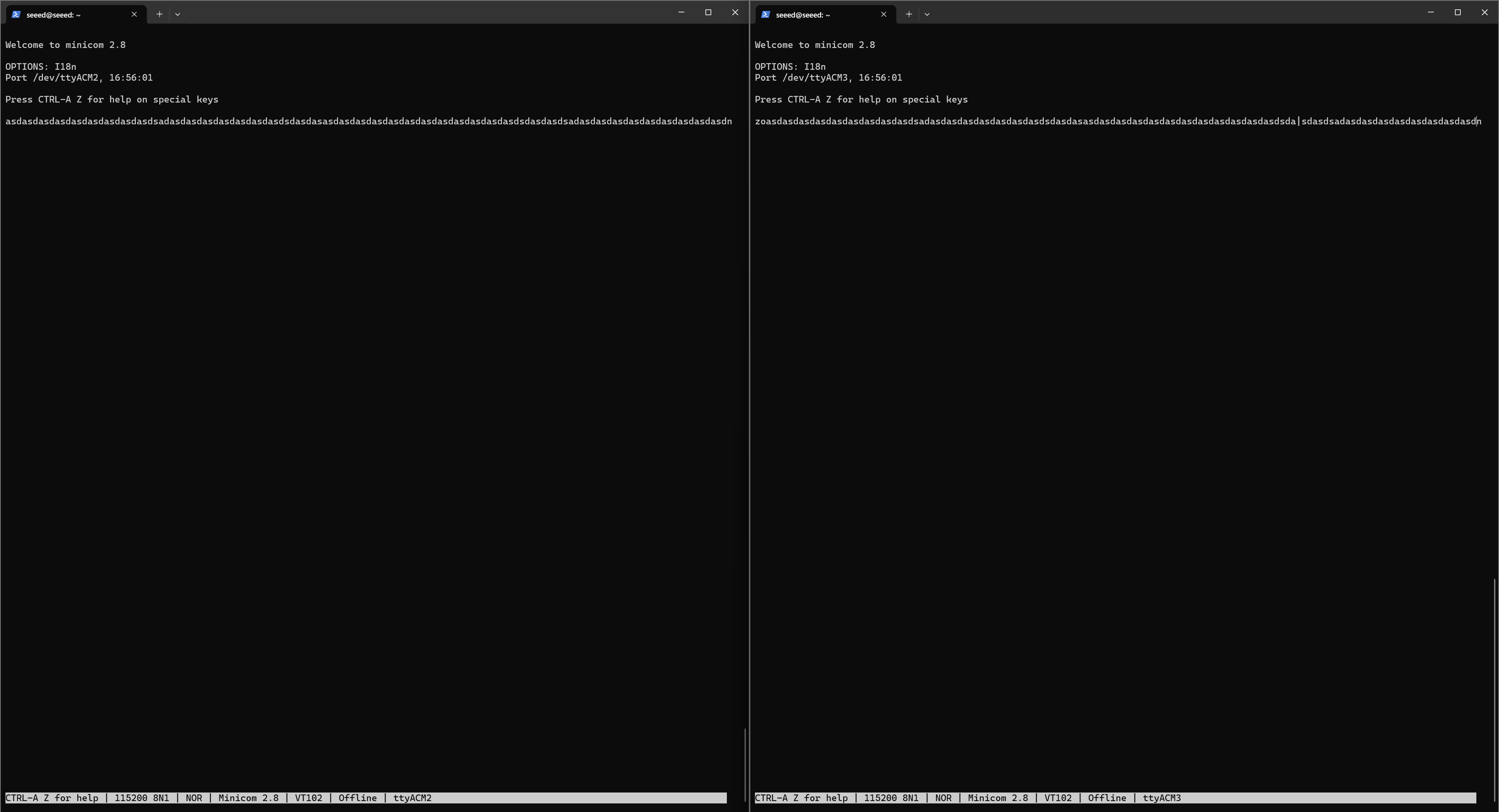
Take ACM2 and ACM3 as an example: If you want to send from ACM2 to ACM3, ACM2 needs to be set up again: ctrl+A , then press Z and then E , and then start the serial port write command. At this time, you can print strings in ACM2 at will, and you can see the contents of ACM2 in ACM3 at the same time; Conversely, if you want to send from ACM3 to ACM2, ACM3 needs to be set up again: ctrl+A, then press Z and then E , and then start the serial port write command. At this time, you can print strings in ACM3 at will, and you can see the contents of ACM3 in ACM2 at the same time. As shown in the figure.
RS232 Testing
reComputer Industrial R21xx includes 2x RS232 ports, and the corresponding COM ports and device files are as follows:
| Number of RS232 Ports | COM Port | Silkscreen Label | Device File |
|---|---|---|---|
| RS232-1 | COM1 | RX1/TX1/GND1 | /dev/ttyACM0 |
| RS232-2 | COM2 | RX2/TX2/GND2 | /dev/ttyACM1 |
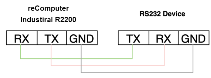
Because RS232 is full-duplex communication, short-circuit the TX and RX of RS232 directly to perform a loopback test.
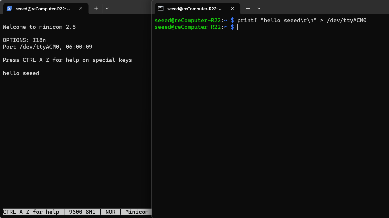
You need to open two terminals, ACM1 if the expansion board is connected, and ACM2 if the expansion board is not connected: Terminal 1:*
sudo minicom -D /dev/ttyACM1 -b 9600
If the expansion board is not connected, you need to change /dev/ttyACM1 to /dev/ttyACM0 .
Terminal 2:
printf "hello seeed\r\n" > /dev/ttyACM1
Terminal 1 will display the content requested by Terminal 2 to be printed.
DI (Digital Input) Testing
reComputer Industrial R21xx contains 4x DI ports, user can configure these ports according to actual needs.
| Number of ports | DI ports | Corresponding extended GPIO |
|---|---|---|
| 4 | DI1 | GPIO588 |
| DI2 | GPIO589 | |
| DI3 | GPIO590 | |
| DI4 | GPIO595 |
The input type of the DI ports is PNP. It supports input voltage is 5VDC~24VDC,current - 1000mA. To test the functionality of DI, you can follow these steps to test it:
- The connection between the DI port of reComputer Industrial R21xx and the external load has been completed.
- Enter the following command to get the status of GPIO:
echo 588 > /sys/class/gpio/export
echo in > /sys/class/gpio/gpio588/direction
cat /sys/class/gpio/gpio588/value
- When the external level is high, the value of /sys/class/gpio/gpio588/value is 0; when the external level is low, /sys/class/gpio/gpio588/value is 1.
DO (Digital Output)
reComputer Industrial R21xx contains 4x DO ports, user can configure these ports according to actual needs.
| Number of ports | DI ports | Corresponding extended GPIO |
|---|---|---|
| 4 | DO1 | GPIO638 |
| DO2 | GPIO637 | |
| DO3 | GPIO590 | |
| DO4 | GPIO636 | |
| DO5 | GPIO635 |
The output type of the DO ports is transistor. It supports output voltage - under 60 VDC, current capacity - 500 mA. To test the functionality of DO, you can follow these steps to test it:
- The connection between the DO port of reComputer Industrial R21xx and the external load has been completed.
- Enter the following command to set the output to high level or low level:
echo 638 > /sys/class/gpio/export
echo out > /sys/class/gpio/gpio638/direction
echo 1 > /sys/class/gpio/gpio638/value
echo 0 > /sys/class/gpio/gpio638/value
- When the external level is high, the value of /sys/class/gpio/gpio638/value is 0; when the external level is low, /sys/class/gpio/gpio638/value is 1.
CAN Testing
Loopback test
| Number of ports | DI ports | Corresponding extended GPIO |
|---|---|---|
| 2 | CAN_H/CAN_L | can0 |
Since the reComputer Industiral R22xx is equipped with only a single CAN interface, it cannot perform independent loopback testing. To verify its communication functionality, an external peer device or a USB-to-CAN adapter is required. For this test, the reComputer Industiral R21xx (featuring dual CAN interfaces) will serve as the peer node to establish a connection with the reComputer Industiral R22xx. Please refer to the following tutorial for specific connection schemes and configuration steps:
- Use two DuPont wires to short-circuit the H-H and L-L of can0 and can1 to form a minimum loop test.
CAN_H─────●───── CAN-H
CAN_L─────●───── CAN-L
G_CAN_H─────●───── G_CAN
- Confirm that the two network interfaces can0 and can1 do appear in the system to prevent the driver from not loading:
# should print can0 can1
ls /sys/class/net | grep can
# should see "successfully initialized"
dmesg | grep -i can
- Set the two CAN interfaces to 500 kbit/s and go online, ready to send and receive data (set them to low level for safety): R22xx:
sudo ip link set can0 down
sudo ip link set can0 up type can bitrate 500000
R21xx:
sudo ip link set can1 down
sudo ip link set can1 up type can bitrate 500000
- Communication Test (One-Way) Use can-utils to send and receive data.
Step A: R21xx (CAN1) Sends → R22xx (CAN0) Receives
-
R22xx: candump can0
-
R21xx: cansend can1 123#DE.AD.BE.EF.CA.FE.00.11
Step B: R22xx (CAN0) Sends → R21xx (CAN1) Receives
-
R21xx: candump can1
-
R22xx: cansend can0 555#1122334455667788
USB Hub Testing
To test the USB hub, you can use the following steps:
- Check if the USB hub is detected by running the lsusb command. This command lists all connected USB devices, including hubs.
lsusb
Running this command should display information about the USB devices connected to your system, including any USB hubs that are present. If the USB hub is functioning properly, you should see its details listed in the output of the lsusb command. If it's not listed, there may be an issue with the hub or its connection to the system. In such cases, you may need to troubleshoot the USB hub or its connections.
RTC (Real-Time Clock) Testing
To test the Real-Time Clock (RTC) functionality, follow these steps:
- Disable automatic time synchronization:
sudo systemctl stop systemd-timesyncd
sudo systemctl disable systemd-timesyncd
- Set the time: Set the RTC to a specific date and time:
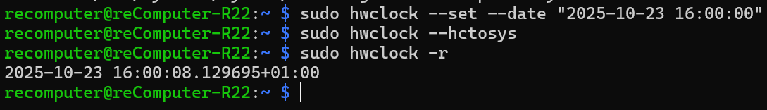
sudo hwclock --set --date "2025-10-23 16:00:00"
- Sync RTC Time to the System Update the system time to match the RTC time:
sudo hwclock --hctosys
- Check the RTC time:
sudo hwclock -r
This command will read and display the time stored in the RTC.
- Disconnect the power source from the RTC, wait a few minutes, then reconnect it and check the RTC time again to see if it retained the correct time.
Watchdog Timer Testing
To perform a watchdog test, follow these steps:
- Install the watchdog software:
sudo apt install watchdog
- Edit the watchdog configuration file:
# make sure you install vim already, if haven't, can install by the command below
sudo apt-get install vim
sudo vim /etc/watchdog.conf
Modify the configuration as follows:
watchdog-device = /dev/watchdog
# Uncomment and edit this line for hardware timeout values that differ
# from the default of one minute.
watchdog-timeout = 120
# If your watchdog trips by itself when the first timeout interval
# elapses then try uncommenting the line below and changing the
# value to 'yes'.
#watchdog-refresh-use-settimeout = auto
# If you have a buggy watchdog device (e.g. some IPMI implementations)
# try uncommenting this line and setting it to 'yes'.
#watchdog-refresh-ignore-errors = no
# ====================== Other system settings ========================
#
# Interval between tests. Should be a couple of seconds shorter than
# the hardware time-out value.
interval = 15
max-load-1 = 24
#max-load-5 = 18
#max-load-15 = 12
realtime = yes
priority = 1
You can adjust other settings as needed.
- Ensure the watchdog service is running:
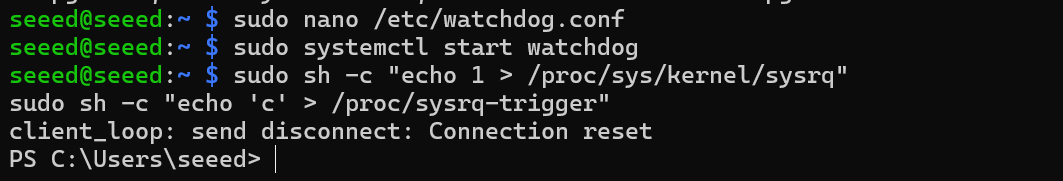
sudo systemctl start watchdog
- To test the watchdog functionality, execute the following command to simulate a system hang:
sudo su

echo 1 > /proc/sys/kernel/sysrq
echo "c" > /proc/sysrq-trigger
This command triggers a kernel crash and should cause the watchdog to reboot the system.
- Monitor the system to confirm that it reboots after the specified timeout period. These steps will help you test and ensure the functionality of the watchdog timer on your system.
Controlling the Buzzer via GPIO
The GPIO corresponding to the buzzer is gpio627. Enter the following script to turn the buzzer on/off :
- Turn on the buzzer :
echo 627 > /sys/class/gpio/export
echo out > /sys/class/gpio/gpio627/direction
echo 1 > /sys/class/gpio/gpio627/value
- Turn off the buzzer :Turn off the buzzer :
echo 627 > /sys/class/gpio/export
echo out > /sys/class/gpio/gpio627/direction
echo 0 > /sys/class/gpio/gpio627/value
TPM 2.0
If you connect TPM 2.0 module to device, the following code can help check TPM connection.
ls /dev | grep tpm
Interpreting the Output:
If you see tpm0 and tpmrm0 in the output, it means that TPM (Trusted Platform Module) devices are detected and available on your system. This indicates that the TPM hardware is recognized and accessible, which is a good sign. You can proceed with using TPM-related functionalities or applications knowing that the devices are present and accessible.
ATECC608A
To interact with the ATECC608A device and generate a random serial number, follow these steps:
- Clone the atecc-util Repository:
curl -LJO https://github.com/wirenboard/atecc-util/releases/download/v0.4.12/atecc-util_0.4.12_arm64.deb
- Extract the contents of the .deb package to the current directory:
dpkg -x ./atecc-util_0.4.12_arm64.deb .
- Navigate to the atecc Directory:
cd usr/bin
- Generate a Random Serial Number:
./atecc -b 10 -s 192 -c 'serial'
This command instructs the ATECC utility to use slot 10 (-b 10), set the serial number size to 192 bits (-s 192), and generate a random serial number (-c 'serial'). The output will be the generated serial number, such as "01235595d3d621f0ee". This process allows you to interact with the ATECC608A device and perform various operations, such as generating random serial numbers.
Interacting with EEPROM
Here are the commands to interact with an EEPROM (Electrically Erasable Programmable Read-Only Memory):
- Grant full permissions (read, write, and execute) to the EEPROM device file:
sudo chmod 777 /sys/bus/i2c/devices/10-0050/eeprom
- Write the string "This is a test string" to the EEPROM device:
echo "This is a test string" > /sys/bus/i2c/devices/10-0050/eeprom
- Read the contents of the EEPROM device and displays it in hexadecimal format using the hexdump utility:
cat /sys/bus/i2c/devices/6-0050/eeprom | hexdump -C
Checking SSD Detection
To list the disks, including the SSD, you can use the fdisk -l command. Here's how:
sudo fdisk -l
This command will display a list of all disks connected to your system, including the SSD if it's properly detected. Look for entries that represent your SSD. They typically start with /dev/sd followed by a letter (e.g. /dev/sda, /dev/sdb, etc.). Once you identify the entry corresponding to your SSD, you can proceed with partitioning or formatting it as needed.
UPS for Safe Shut Down
A GPIO6 between CPU and DC power in is used to alarm CPU when the power supply is down. Then the CPU should do something urgent in a script before energy exhaustion of super capacitor and run a "$ shutdown". Another way to use this function is Initiate a shutdown when GPIO pin changes. The given GPIO pin is configured as an input key that generates KEY_POWER events. This event is handled by systemd-logind by initiating a shutdown.
- Hardware connection.
Please make sure that the 'CM5_UPS_DET' pin of the UPS device is connected to the GPIO16 pin of the R21xx device.
- Modify the configuration file.
- Open the terminal.
- Execute the following command to edit the configuration file:
sudo nano /boot/firmware/config.txt
- Add the following content at the end of the file:
dtoverlay=gpio-shutdown,gpio_pin=GPIO16,active_low=1
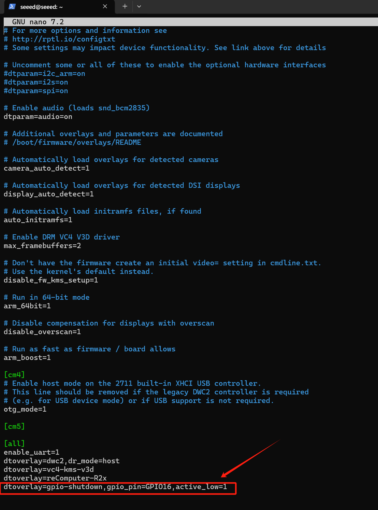
Save and exit the editor (press Ctrl+O to save, Enter to confirm, and Ctrl+X to exit).
- Prepare Python script
- Create a new Python script file:
cd ~
sudo nano ups_shutdown.py
- Copy and paste the following code into the file:
import RPi.GPIO as GPIO
import time, os

num = 0

GPIO.setmode(GPIO.BCM)

# Set GPIO16 to input mode
# Add 500ms anti-shake time to stabilize the software
GPIO.setup(16, GPIO.IN, pull_up_down=GPIO.PUD_UP)
GPIO.add_event_detect(16, GPIO.FALLING, bouncetime=500)

while True:
    if GPIO.event_detected(16):
        print("...External power off...")
        print("")

        # Sync data to disk
        os.system('sync')
        print("...Data saving...")
        print("")

        # Sleep for 3 seconds
        time.sleep(3)

        # Synchronize data again
        os.system('sync')

        # Countdown 5 seconds
        while num < 5:
            print('----------')
            s = 5 - num
            print('---' + str(s) + '---')
            num = num + 1
            time.sleep(1)
            print('----------')

        # Execute shutdown command
        os.system('sudo shutdown -h now')
Save and exit the editor (press Ctrl+O to save, Enter to confirm, and Ctrl+X to exit).
- Run the script.
- Open the terminal.
- Execute the following command to run the script:
sudo python3 ups_shutdown.py
Use sudo to ensure that the script has sufficient permissions to execute the shutdown command.
- Simulate power failure test
- Cut off the external power supply.
- Observe whether the system automatically saves data and shuts down.
- Verify the result
- Reconnect the power supply.
- Check whether the system data is complete and starts normally.
- For UPS function please contact us for more information.
- The alarm signal is active LOW.
AI Accelerator
The M.2 M-KEY 2240 slot on the reComputer Industrial R21xx is designed to accommodate PCIE M.2 AI Accelerator. And the R21xx-12 series has been pre-installed with a Hailo-8 M.2 AI Acceleration up to 26TOPS. If you purchased the R21xx-10 series product, you will need to purchase Hailo's NPU module to enable AI functionality. The device comes pre-installed with the Hailo accelerator driver, so you can use it directly and run the test case:
- Navigate to the test case directory
cd /mnt/hailo-rpi5-examples/
- Start the virtual environment
source ./setup_env.sh
- Run the simple detection example
python basic_pipelines/detection_simple.py
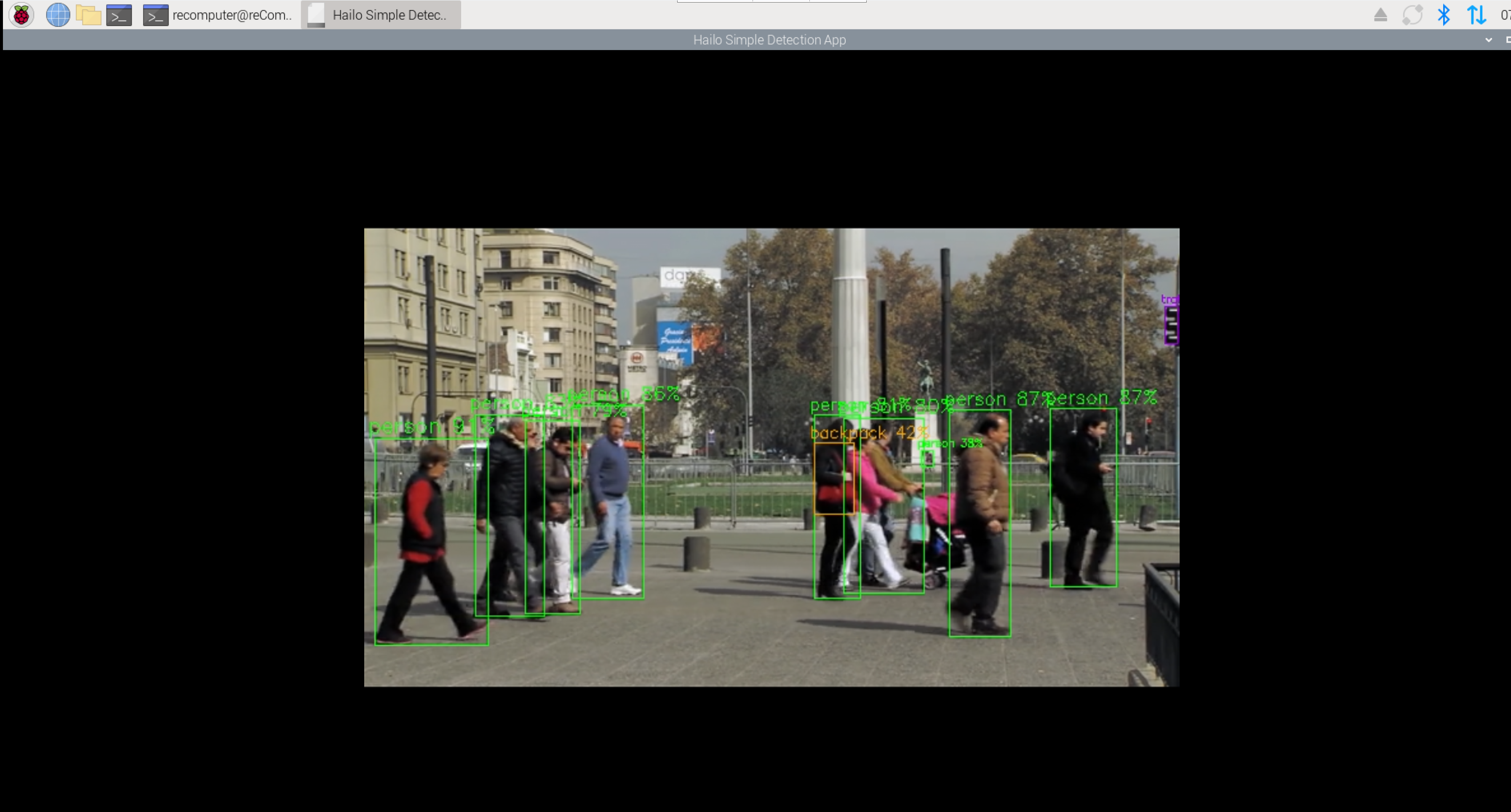
To close the application, press Ctrl+C .
This is lightweight version of the detection example, mainly focusing on demonstrating Hailo performance while minimizing CPU load. The internal GStreamer video processing pipeline is simplified by minimizing video processing tasks, and the YOLOv6 Nano model is used.
If the reComputer you purchased does not include Hailo-8 and you are considering purchasing a Hailo device for integration, please refer to the official Hailo documentation (https://github.com/hailo-ai) to configure the firmware and environment, and run the examples to verify that the device can be used normally.
PoE IP Camera
The reComputer Industrial R22xx series is designed for high-density IP video streams and industrial automation. It features 5 physical Gigabit Ethernet ports with a hybrid bus architecture to ensure maximum bandwidth and stability.
Internal Bus Distribution:
- eth0 (Native): Directly connected to the SoC. It offers the lowest latency and is recommended as the Primary Uplink (WAN) or Management Port.
- eth1 (USB Extension): The standalone port located next to the native port. It is extended via the USB 3.0 bus and supports PoE output.
- eth2, eth3, eth4 (PCIe Extension): The three consecutive ports. These are extended via the PCIe bus and support PoE output.
- Technical Specifications
| Category | Specification | Notes |
|---|---|---|
| Total Ports | 1 (Native) + 4 (Extended) | 5x RJ45 Gigabit Ethernet |
| PoE Mode | Alternative A (Mode A) | Power delivered over data pairs (1/2, 3/6) |
| PoE Output per Port | 12W (Max) | Optimized for standard IP cameras |
| Parallel PoE Output | All 4 ports support 12W simultaneously | Requires sufficient system power input |
| Power Input Range | 9V - 36V DC | Internal boost circuit steps up to 48V for PoE |
| Safety Features | Over-current & Under-voltage Protection | Hot-plugging is strictly prohibited |
- Critical Safety Guidelines
- NO HOT-PLUGGING:
WARNING: Plugging or unplugging Ethernet cables while PoE power is active (GPIO High) can cause transient surges that may damage the LAN7800 or PCIe bridge chips. Always follow the "Connect First, Power Second" principle.
- Power Supply Recommendations:
While the device supports 9V input, we recommend using a 24V industrial power supply with at least 72W (3A) capacity to ensure high conversion efficiency when all 4 PoE ports are under full load (4 × 12W).
- Configuration Steps
- Step 1: Disable Conflicting Services
To prevent desktop-grade network managers from overwriting industrial static IP settings, disable
NetworkManager.
# Switch to systemd-networkd
sudo systemctl disable --now NetworkManager
sudo systemctl mask NetworkManager
sudo systemctl enable --now systemd-networkd
- Step 2: Enable Auto-Power for PoE (GPIO)
Add the following commands to
/etc/rc.localbefore theexit 0line to ensure PoE power is enabled on boot.
# Export and set PoE Enable Pin (Example: GPIO 532)
echo 652 > /sys/class/gpio/export
echo out > /sys/class/gpio/gpio652/direction
echo 1 > /sys/class/gpio/gpio652/value
- Step 3: Multi-Interface IP Deployment
Assign independent subnets to each port and use RouteMetric to ensure
eth0remains the default gateway for internet access.
# Configure eth0 (WAN/DHCP) - Highest Priority
sudo bash -c 'cat > /etc/systemd/network/10-eth0.network <<EOF
[Match]
Name=eth0
[Network]
DHCP=yes
[DHCPv4]
RouteMetric=10
EOF'

# Configure eth1-eth4 (Static IP Segments)
for i in {1..4}; do
sudo bash -c "cat > /etc/systemd/network/20-eth$i.network <<EOF
[Match]
Name=eth$i
[Network]
Address=10.0.$((i+2)).10/24
[IPv4]
RouteMetric=$((100+i))
EOF"
done
- Verification & Troubleshooting
- Check Bus Connectivity
Use
lspciandlsusbto verify that all controllers are recognized by the system:
- PCIe Extended Ports (eth2-4): Run
lspci | grep Ethernet - USB Extended Port (eth1): Run
lsusb -tand look for thelan78xxdriver.
- FAQ
- Q: Why does my camera keep rebooting?
- A: Check if the camera's power consumption exceeds 12W. High-power PTZ cameras or those with strong IR illuminators may exceed this limit.
- Q: Can I use 12V DC input for PoE?
- A: Yes. The internal circuit will boost 12V to 48V. However, ensure your 12V power supply can handle high current, as the conversion loss is higher at lower input voltages.
- Q: The interface name is not eth1-4.
- A: Use
ip linkto find the actual kernel name (e.g.,enp1s0) and update theName=field in your.networkfiles.
- A: Use
- 4-Channel PoE Camera Support Status:
reComputer R22 & reCamera
This guide provides a step-by-step walkthrough for connecting a reCamera — an open-source, modular AI camera powered by the RISC-V platform and designed for rapid Edge AI deployment — to the reComputer R22 via PoE. It covers deploying an RTSP stream using Node-RED and previewing the live feed on the R22.
- Hardware Connection & Initialization
- Compatible Models: reCamera series (PoE version, e.g., LH-AR01).
- Physical Connection: Connect the reCamera to any PoE port (eth1-eth4) on the R22 using a standard Ethernet cable.
- Enable PoE Power:
Run the following commands in the R22 terminal to enable the 48V output:
# Enable GPIO 652
echo 652 > /sys/class/gpio/export
echo out > /sys/class/gpio/652/direction
echo 1 > /sys/class/gpio/652/value

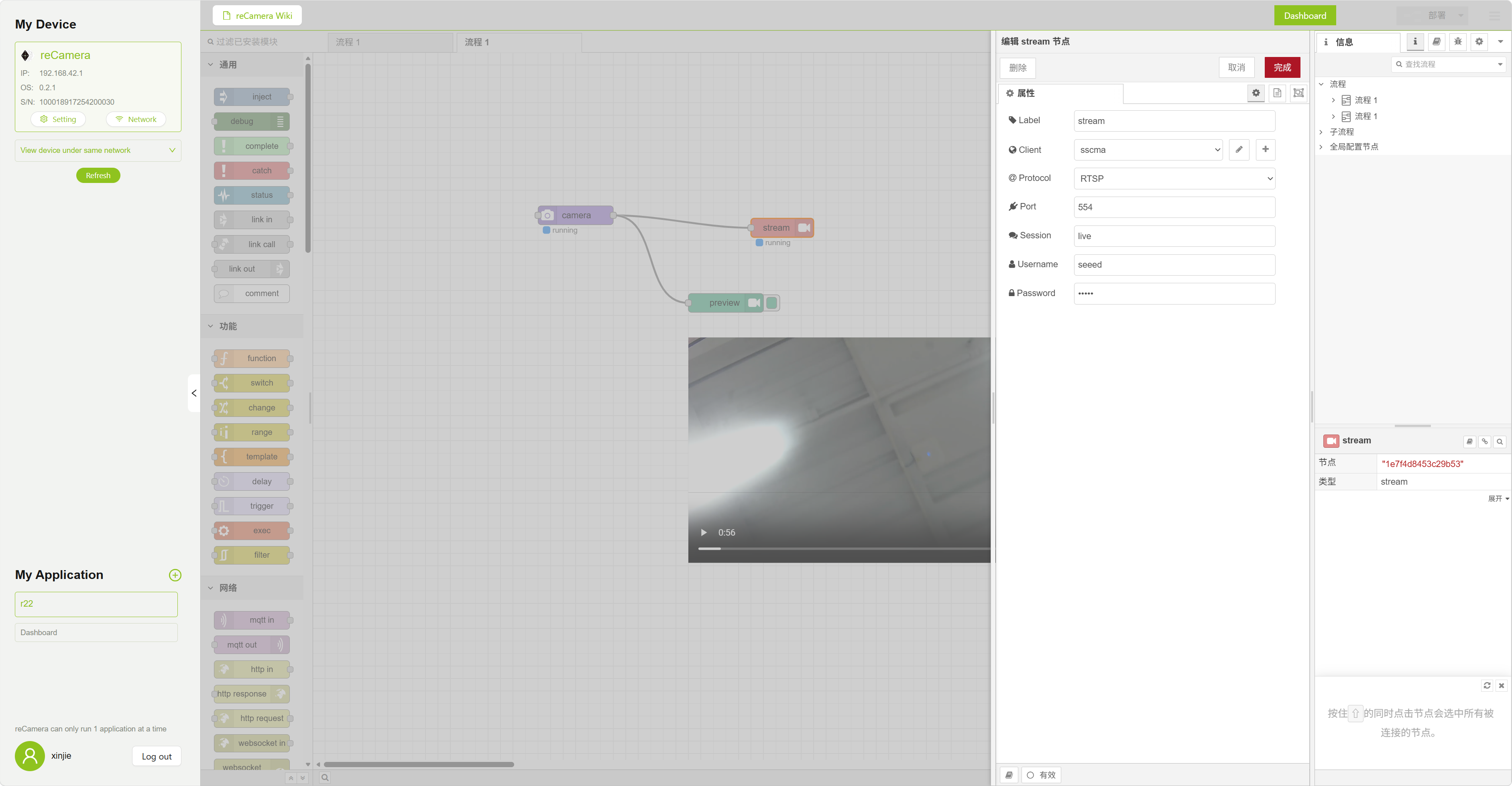
- reCamera Configuration (One-Click Node-RED Import)
Use the pre-configured flows.json to quickly deploy an authenticated RTSP stream.
- Access Dashboard: Open your browser and go to
http://10.0.3.200:1880(reCamera default IP). - Import Configuration:
- Click the menu icon
≡in the top-right corner -> Import. - Upload the flows.json file and click Import.
- Click the menu icon
- Custom Authentication (Required):
- Double-click the
RTSP Outputnode in the flow. - In the Authentication section, set your credentials:
- Username:
seeed - Password:
seeed
- Username:
- Double-click the
- Deploy: Click the red Deploy button in the top-right corner.
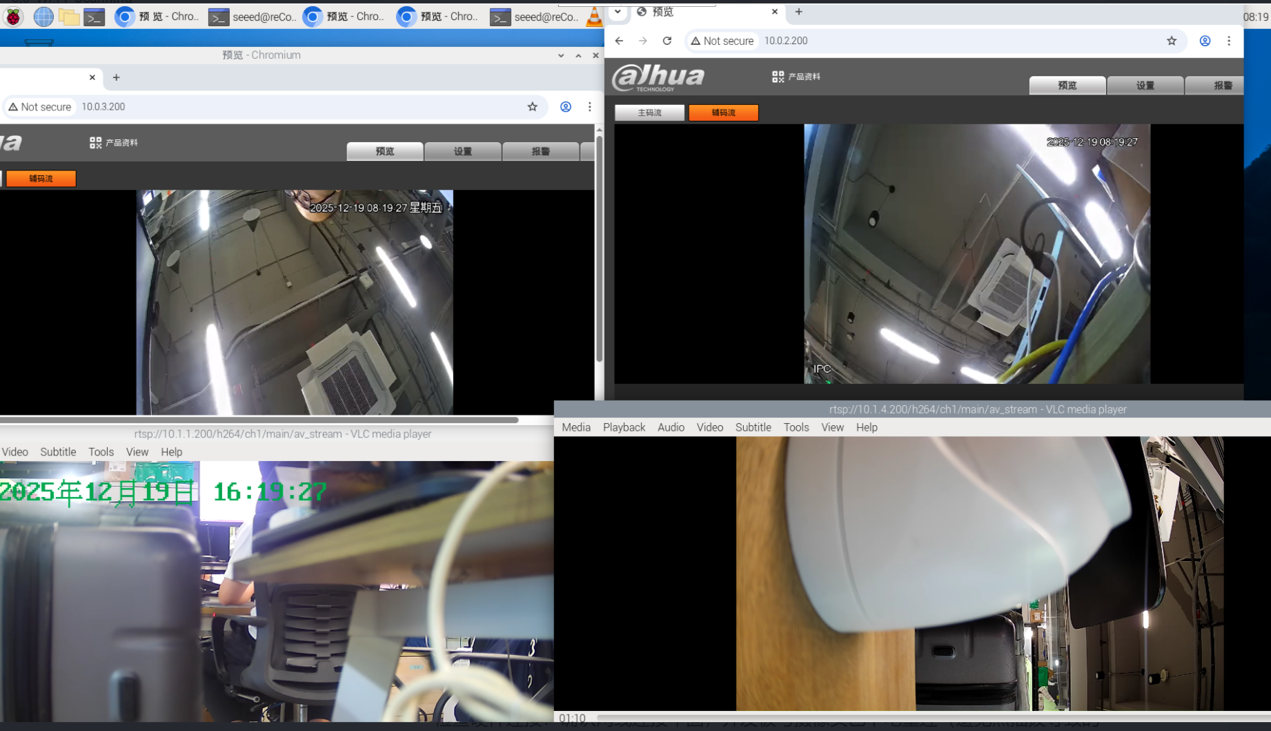
- Previewing Video Stream on R22
Since the R22 (CM4/CM5 based) supports hardware decoding, we recommend using VLC or FFplay for verification.
- Option A: Using VLC GUI (Recommended)
- Type
vlcin the R22 terminal to open the player. - Go to Media -> Open Network Stream.
- Enter the authenticated RTSP URL:
rtsp://seeed:[email protected]:554/live - Click Play.
- Option B: Using Command Line (Quick Test)
Copy and run the following command directly:
ffplay -fflags nobuffer -flags low_delay rtsp://seeed:[email protected]:554/live
- Troubleshooting
| Issue | Potential Cause | Solution |
|---|---|---|
| Cannot Ping 10.0.3.200 | R22 internal IP conflict | Check if eth3/eth4 both use 10.0.3.10. Manually change one. |
| reCamera not booting | PoE power not enabled | Ensure GPIO 652 is set to 1 and input power is > 12V/3A. |
| Video lag/latency | Network or MTU issues | Ensure no heavy broadcast traffic between R22 and reCamera. |

Tech Support & Product Discussion
Thank you for choosing our products! We are here to provide you with different support to ensure that your experience with our products is as smooth as possible. We offer several communication channels to cater to different preferences and needs.