reComputer Mini Hardware and Interfaces Usage
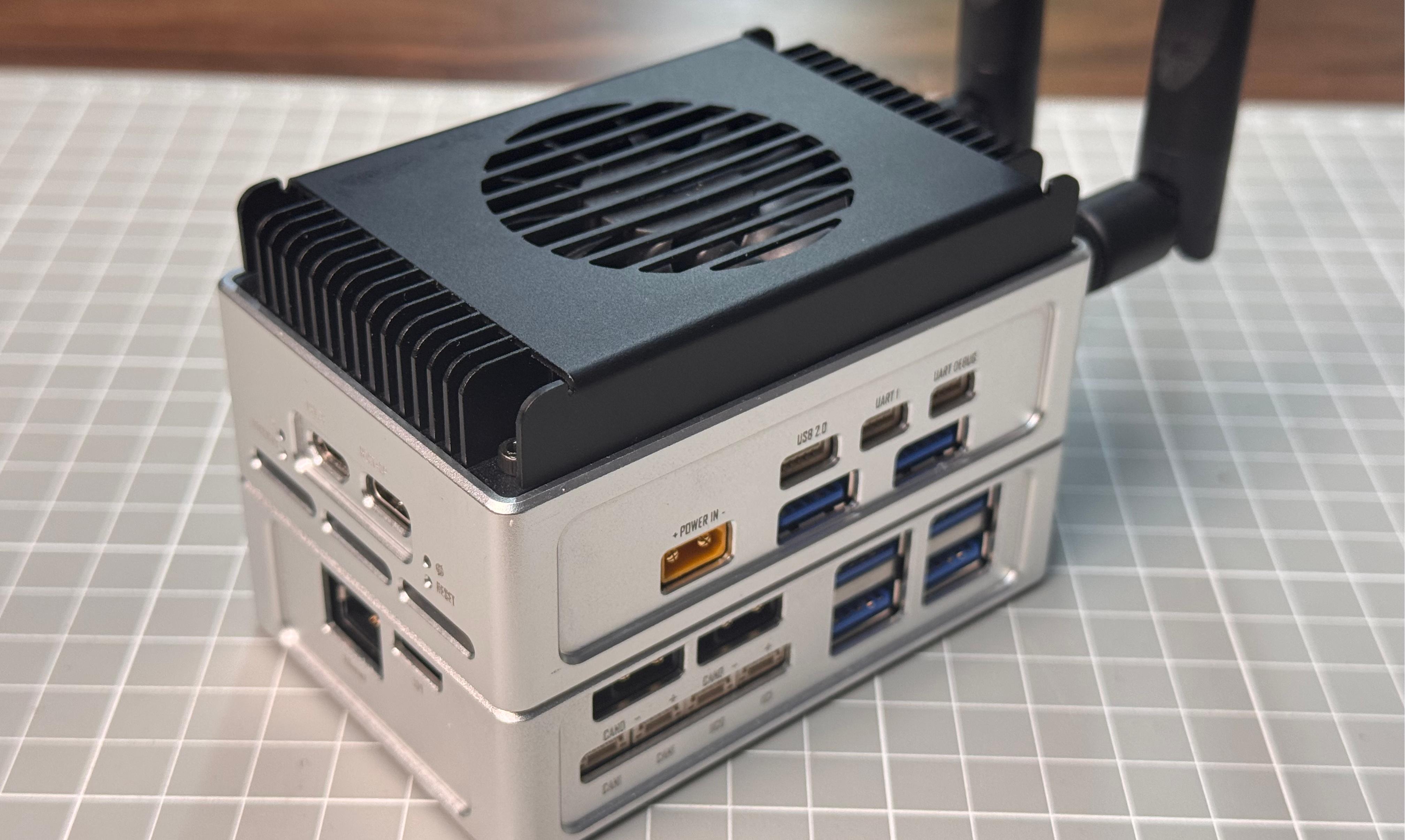
This wiki introduces the various different hardware and interfaces on the reComputer mini J40 series and how to use them to expand your project ideas.
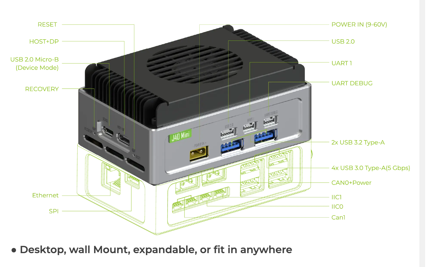
Hardware Interface Overview
Power
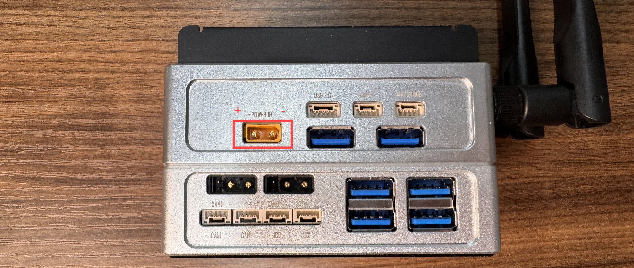
reComputer Mini is equipped with a 12-54V (XT30) power interface, compatible with a wide voltage input range (12V to 54V), making it suitable for various power supply environments.
Display
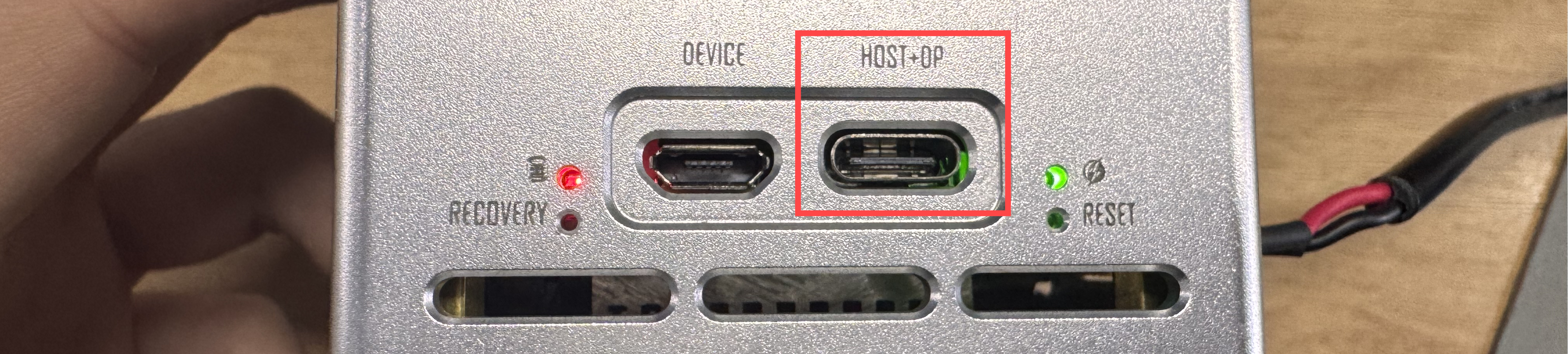
The product is equipped with a Type-C port featuring Host + DP (DisplayPort) functionality, which means it not only supports data transfer but also allows you to connect a monitor via this port, enabling high-quality video output.
M.2 Key E for WIFI and Bluetooth
The reComputer Mini features a M.2 Key E interface, through which you can expand the device's Bluetooth and Wi-Fi capabilities.
We recommend using the Intel Dual Band RTL8822CE Wireless NIC.
Hardware Connection
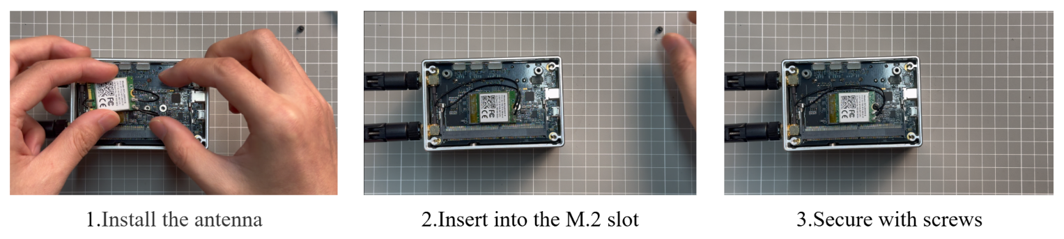
Usage Instruction
After installing the Wi-Fi module and powering on the device, we can configure the device's Wi-Fi and Bluetooth settings.
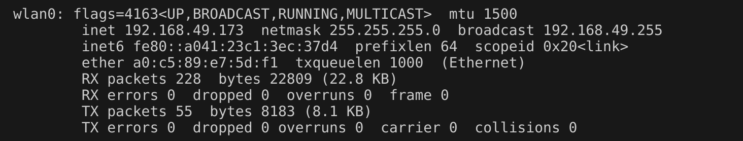
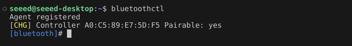
Of course, we can also check the device's operating status using the following commands.
ifconfig
bluetoothctl
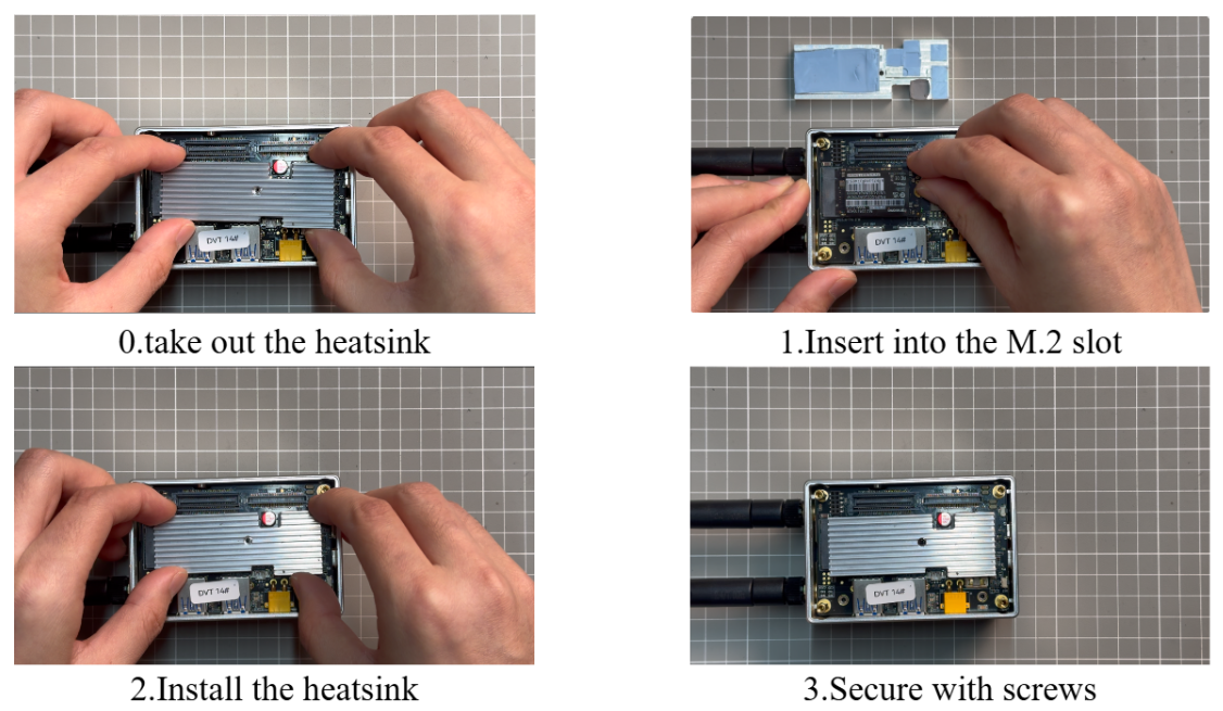
M.2 Key M for SSD
M.2 Key M is an interface designed for high-speed solid-state drives (SSDs), providing ultra-fast data transfer speeds, ideal for high-performance applications.
Out of the box, reComputer Industrial includes a 128GB industrial-grade SSD connected to the M.2 Key M slot with x4 PCIe Gen3, which is pre-installed with JetPack system.
Hardware Connection
If you want to remove the included SSD and install a new one, you need to ensure that your SSD meets the following two conditions:
- Support the M.2 Key M slot with x4 PCIe Gen3 interface.
- Conform to the 2242 size specification.
Usage Instruction
Open the terminal in Jetson device and enter the following command to test the SSD's read and write speed.
sudo dd if=/dev/zero of=tempfile bs=1M count=1024 conv=fdatasync
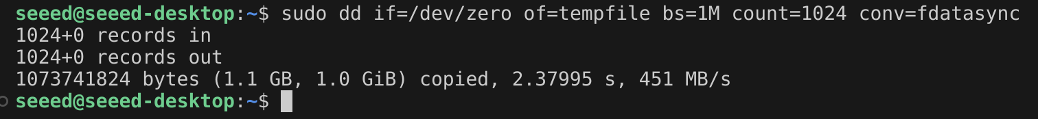
Please run sudo rm tempfile command to delete the cache files after the test is complete.
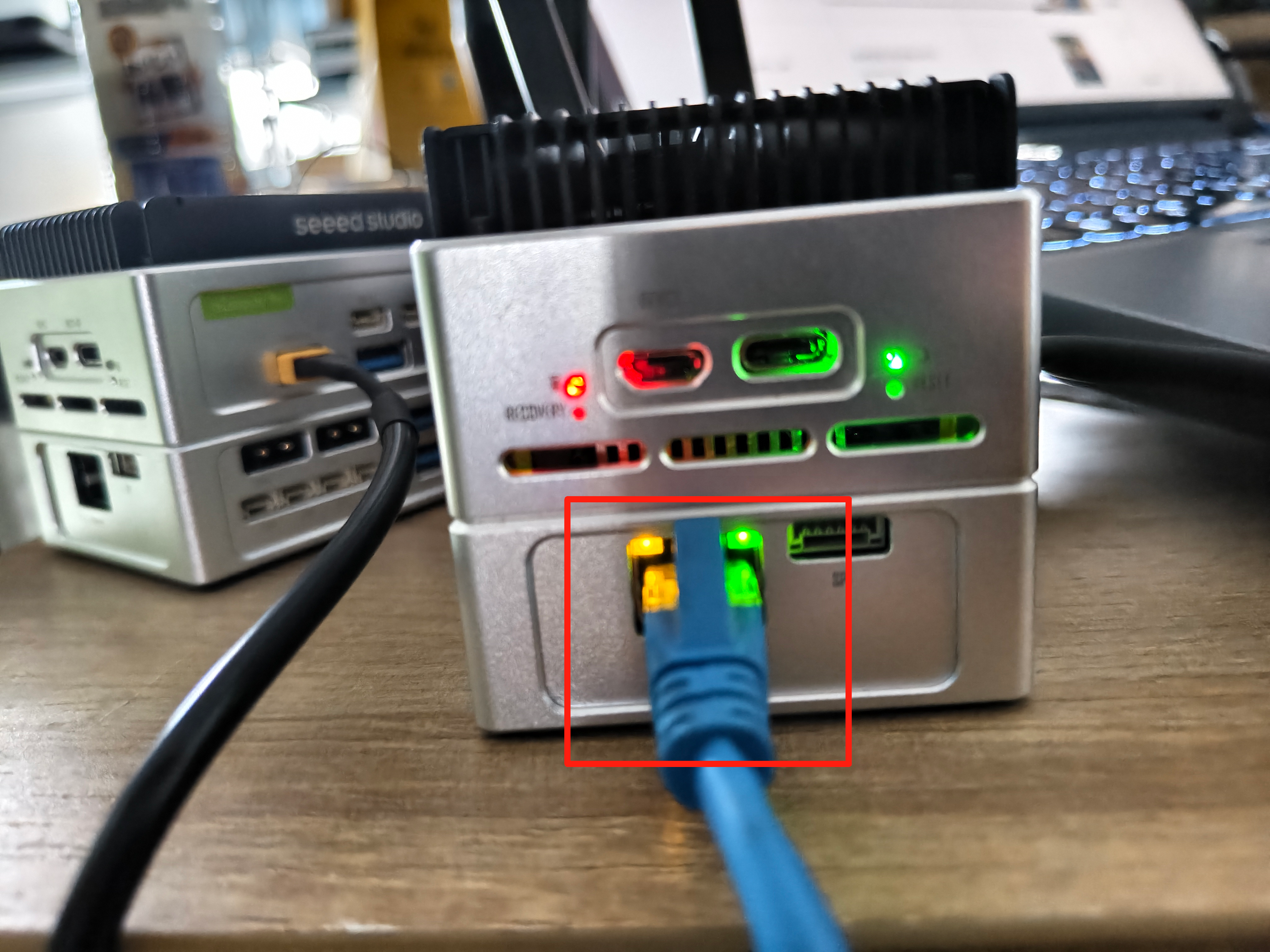
Ethernet
Hardware Connection
The reComputer Mini features an RJ45 Gigabit Ethernet port (10/100/1000M) on the expansion board.
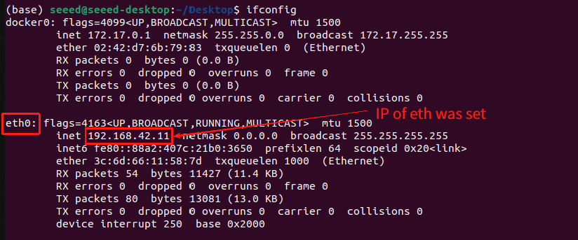
Usage Instruction
Enter ifconfig in the terminal, and you can see the device name mapped by the Ethernet interface is eth0:
Connect the reComputer Mini to PC using a Gigabit Ethernet RJ45 cable. With the tool iperf, we can briefly test the transmission rate of the Ethernet interface.
Open a terminal and install iperf3 on both the PC and the reComputer Mini.
sudo apt update
sudo apt install iperf3
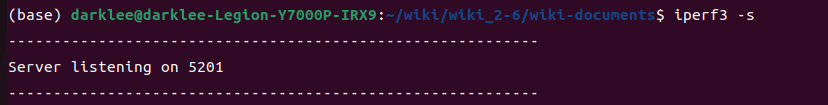
Open the terminal on the PC and enter iperf3 -s.
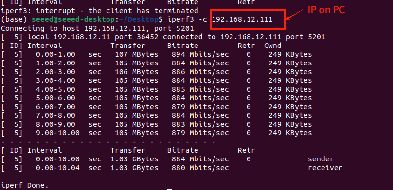
Then, open the terminal on the reComputer Mini and enter iperf3 -c <IP of your PC>.
In this case, the IP address of my PC's network interface is 192.168.12.211. The example command is as follows:
iperf3 -c 192.168.12.211
Then, based on the results shown in the figure below, you can see that the Ethernet transmission speed of the reComputer Mini can reach the gigabit level.
USB
Hardware Connection
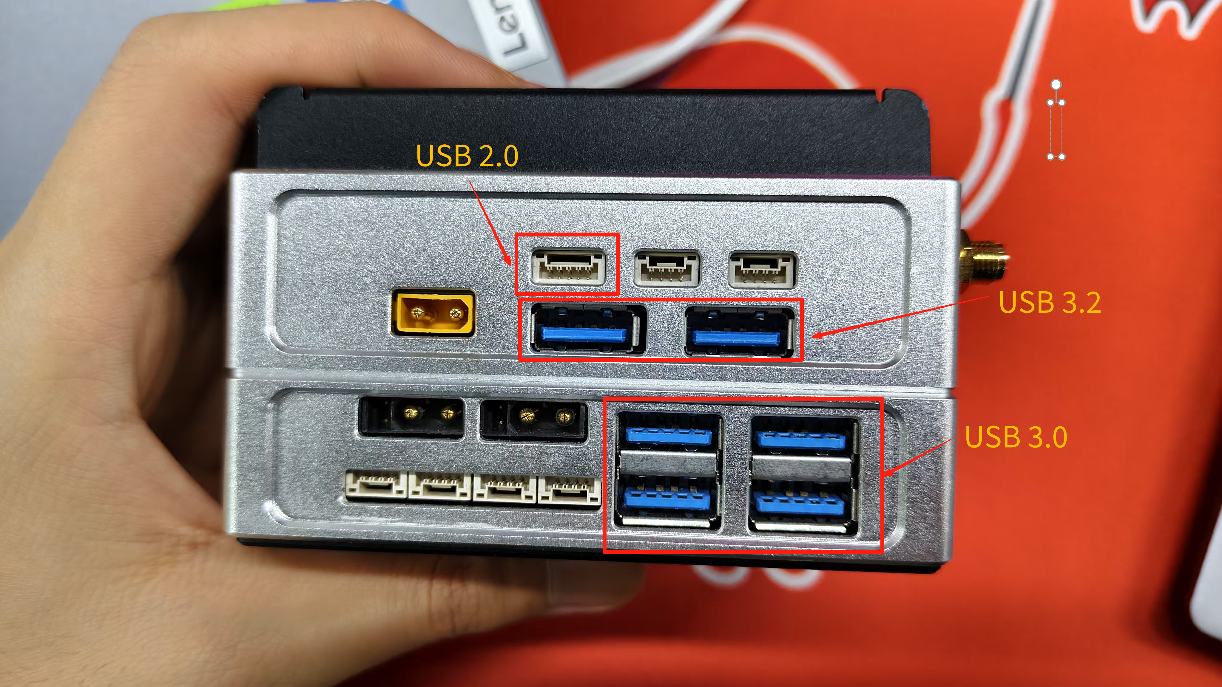
The reComputer Mini carrier board has a total of 4 USB ports: 2 USB 3.2 Type-A ports, 1 USB 2.0 Micro-B port for flash, and 1 USB 2.0 GH1.25 port. And the expansion board has 4 USB 3.0 Type-A ports.
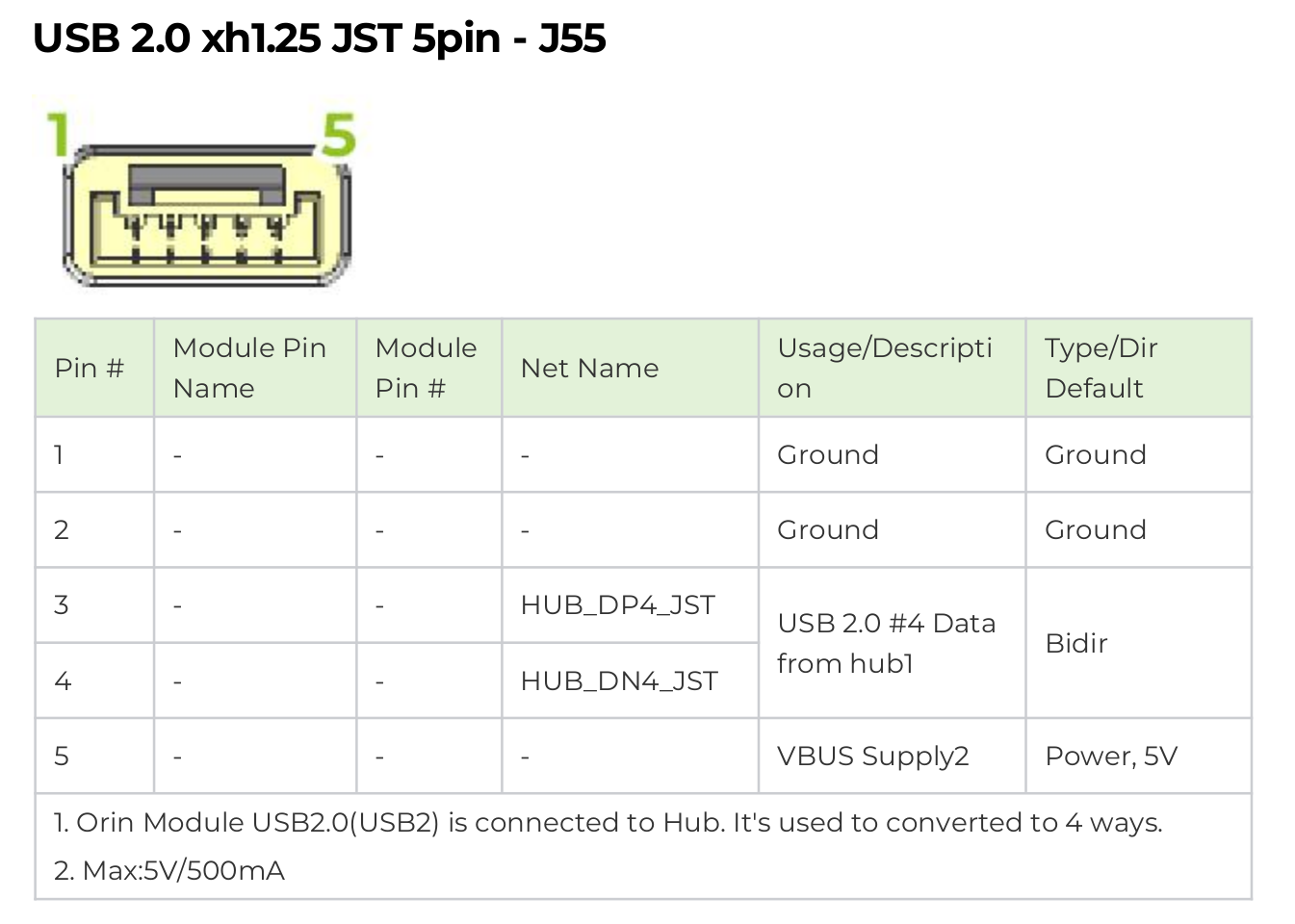
In the datasheet, you can find the wiring diagram for the USB 2.0 5-pin GH-1.25 interface as shown below:
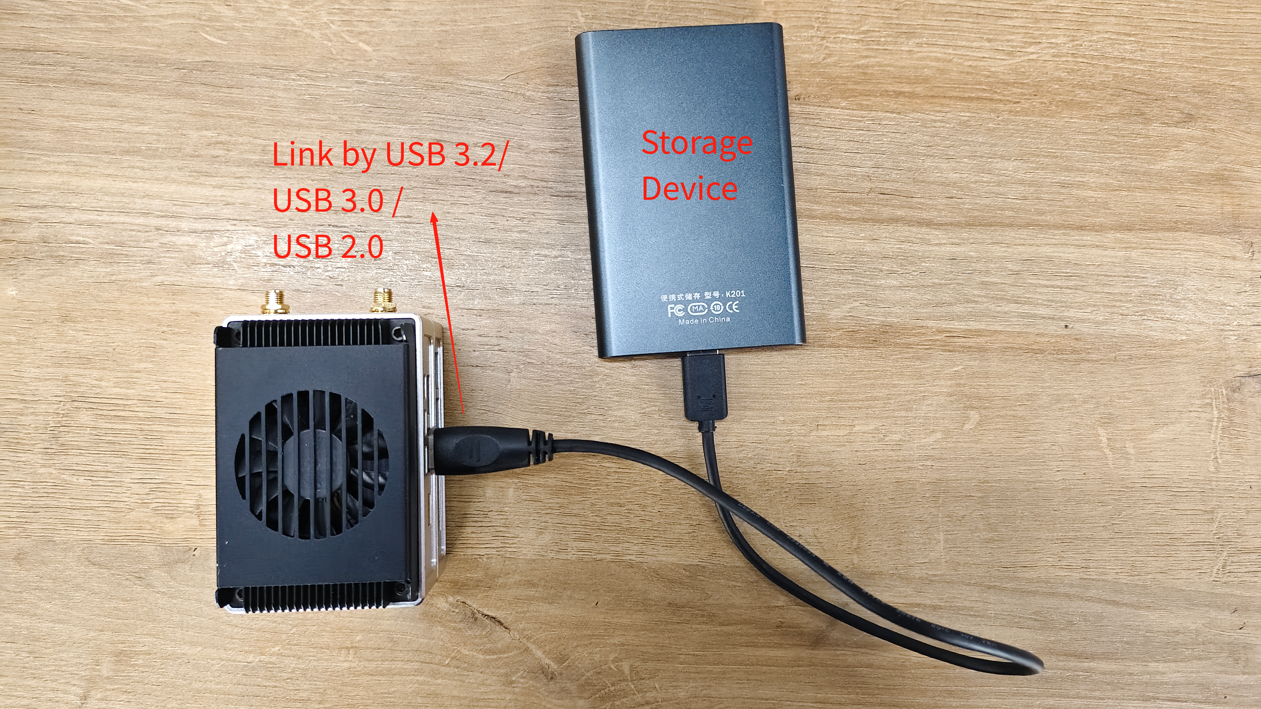
We can refer to the following procedure to connect a storage device to the reComputer mini via USB 3.2/USB 2.0/USB 3.0 for testing USB read and write speeds. The Usage Instruction will display the next steps.
Usage Instruction
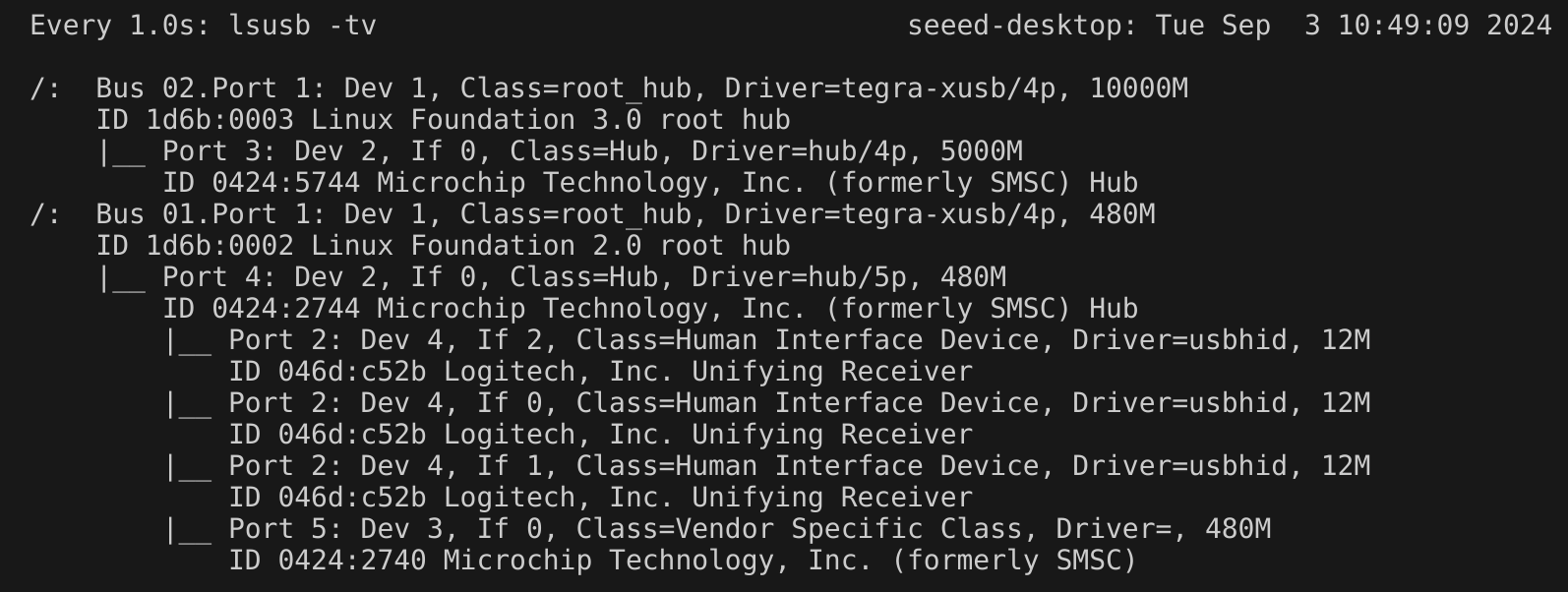
We can enter watch -n 1 lsusb -tv in the Jetson terminal to probe the USB ports. Once a USB device is connected, the detailed information about that port will be displayed here.
After connecting the storage device via USB 3.2/USB 2.0/USB 3.0, enter the following command in the terminal to view the partition mapped by the storage device:
ls /dev/sd*
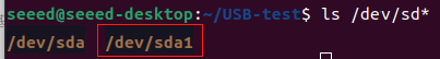
/dev/sda1 is the partition mapped by a storage device connected via USB. If multiple devices are inserted, they may have different mapped partition names. For example: /dev/sdb1.
Pull and run the test program from GitHub to measure the write and read speeds of the USB. The program will write and then read 1GB of temporary data, which will be deleted after the test is completed.
The parameter after sudo ./USBIO depends on the mapped partition of the storage device connected via USB.
git clone https://github.com/jjjadand/Mini_USBIO_test.git
cd Mini_USBIO_test/
gcc -o USBIO USB_test.c
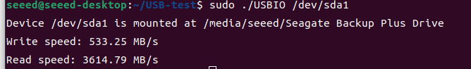
sudo ./USBIO /dev/sda1
The read and write speeds for a 1GB data transfer on an external SSD connected via USB 3.2 are as follows:
The program is also applicable for testing other USB interfaces.
For the usage of the USB Micro-B interface, please refer to this wiki for a detailed tutorial.
UART
The reComputer Mini carrier board has two 4-pin GH-1.25 UART interfaces: UART1 and UART-DEBUG.
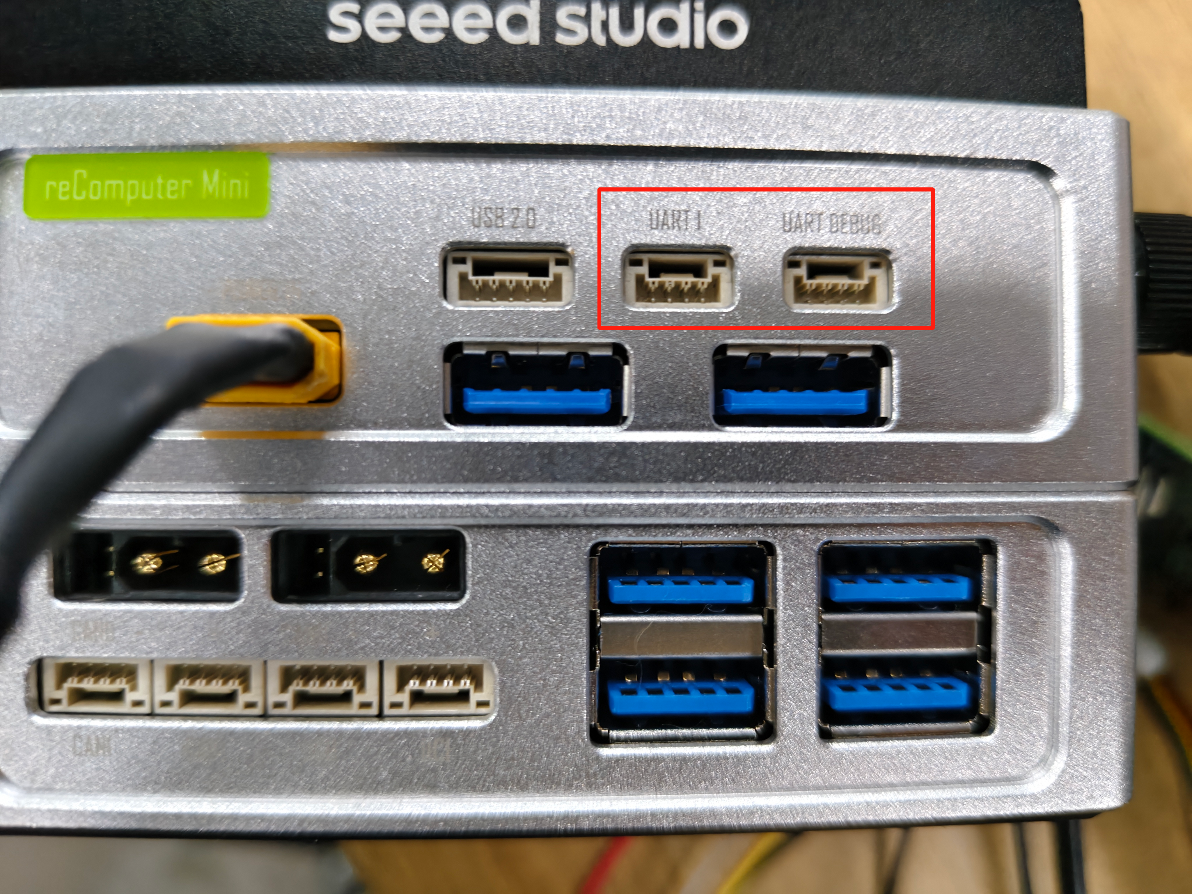
UART1
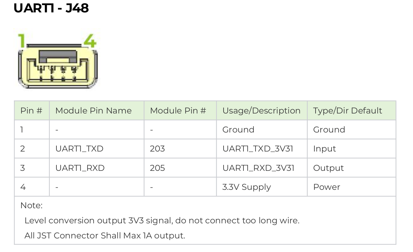
Hardware Connection
In the datasheet, you can find the wiring diagram for the UART1 4-pin GH-1.25 interface as shown below:
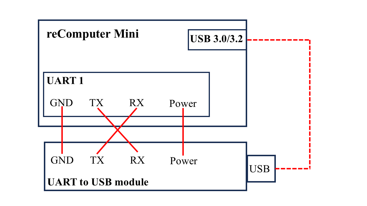
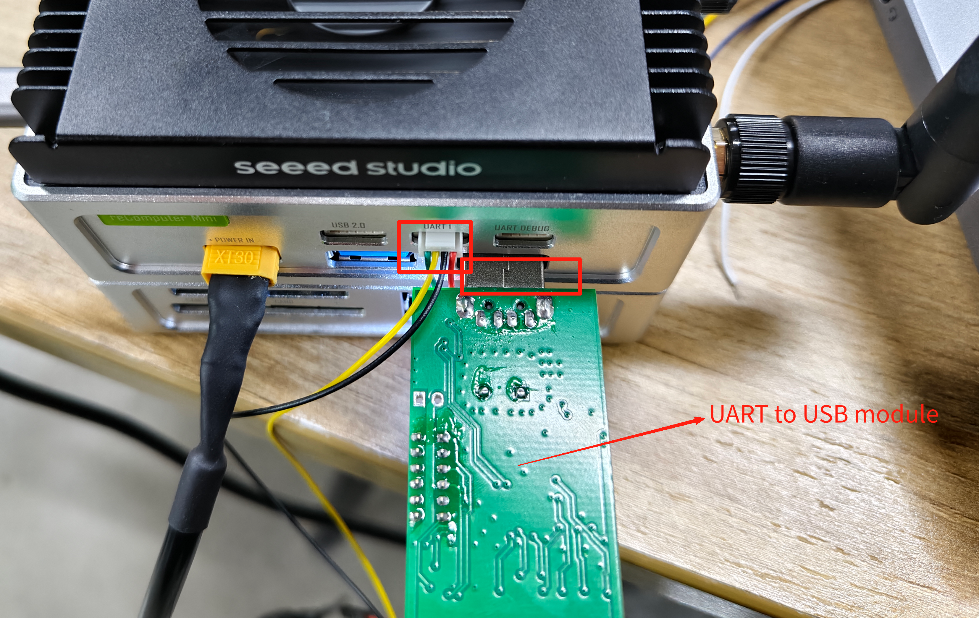
To test and monitor the transmit and receive functionality of UART1, select a suitable UART-to-USB module (based on your requirements), connect it according to the wiring diagram in the datasheet, and then install cutecom.
Connect one end to the 4-pin GH-1.25 interface of UART1, and plug the other end into the USB port, ensuring that Tx is connected to Rx and Rx to Tx. The Usage Instruction will display the next steps.
Usage Instruction
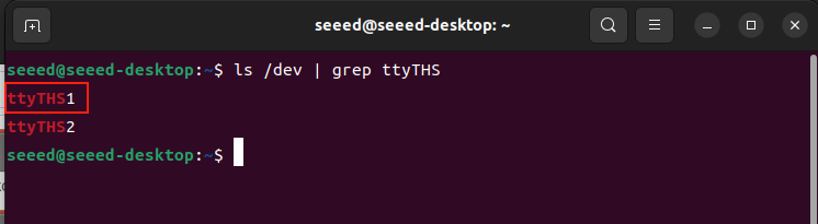
The serial port number recognized by the system for UART1 is: /dev/ttyTHS1. You can check it by entering the following command in the terminal:
Install Cutecom to test UART1 data transmission and reception:
sudo apt update
sudo apt install cutecom
Open Cutecom in two different terminals.
sudo cutecom
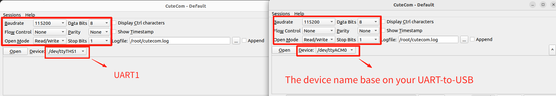
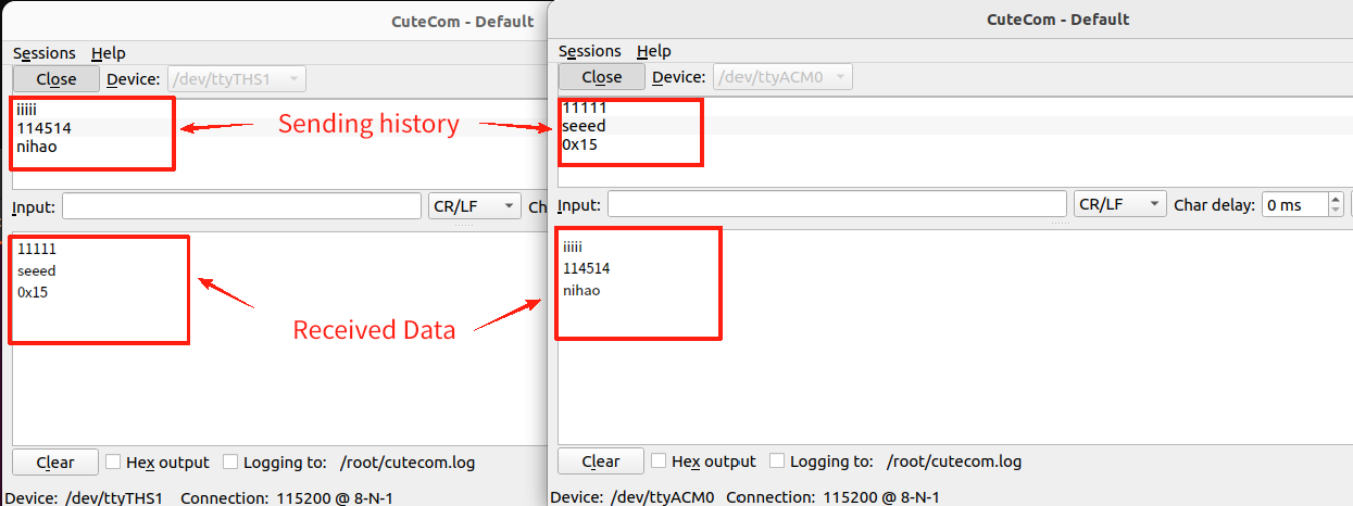
Set the parameters according to the figure below: In one terminal, select /dev/ttyTHS1 for the “device” option. In the other terminal, the “device” should be chosen based on the UART-to-USB module you are using. You can enter messages in the “Input” field to test the transmission and reception of data.
UART-DEBUG
Hardware Connection
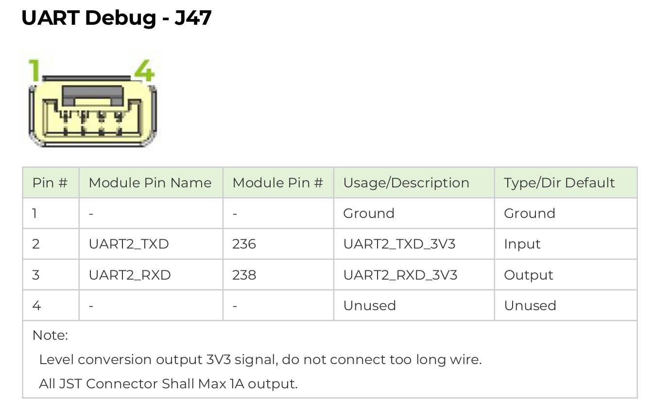
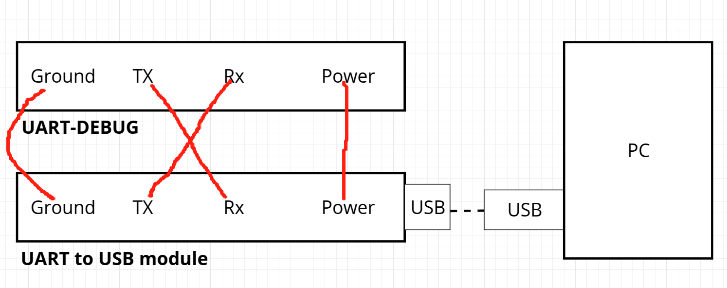
In the datasheet, you can find the wiring diagram for the UART-DEBUG 4-pin GH-1.25 interface as shown below:
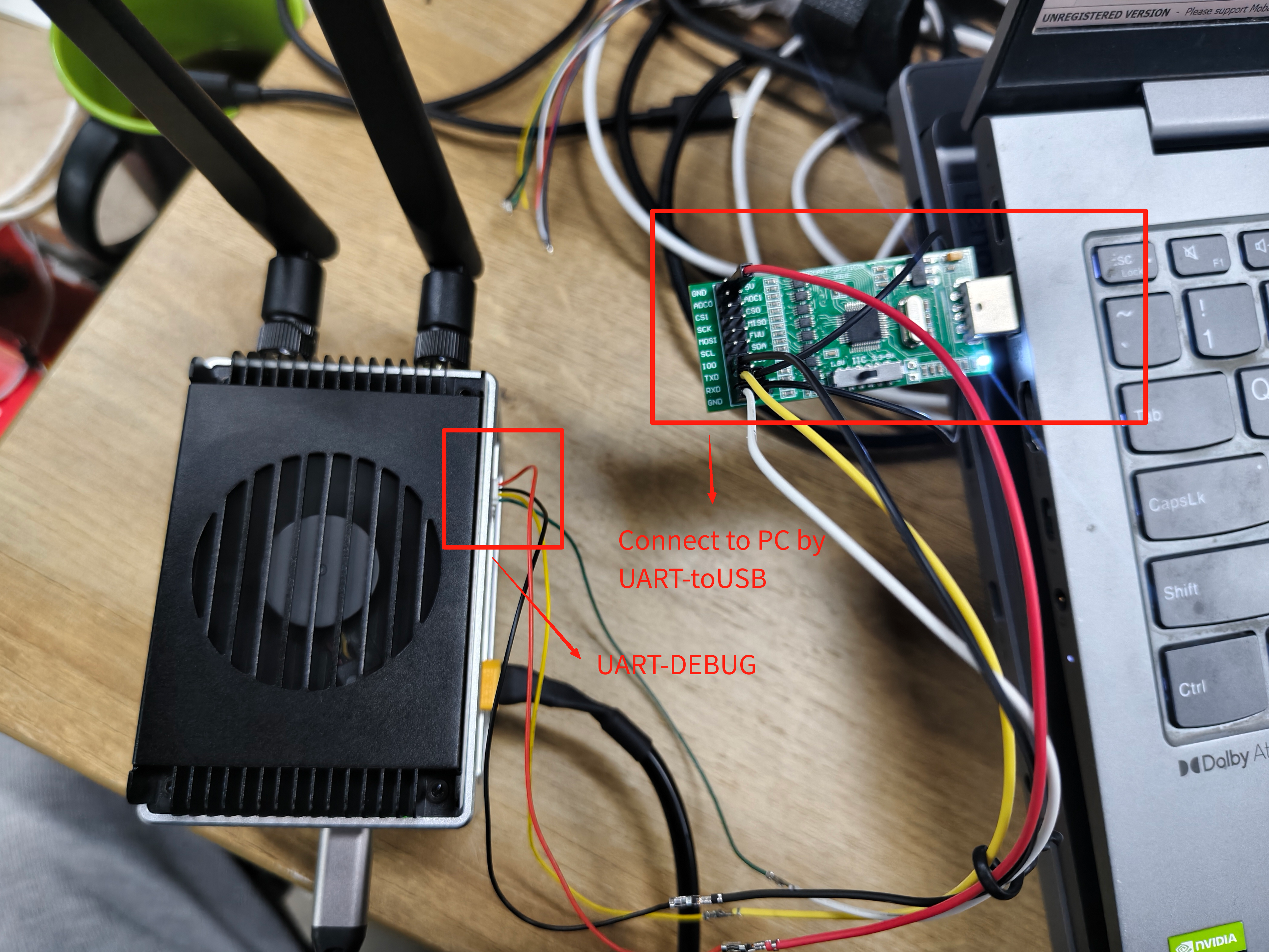
To test UART-DEBUG, you also need a UART-to-USB module, which should be connected to your PC as shown in the figure below.
Usage Instruction
After completing the hardware connections.
Install the serial port login tool MobaXterm on your PC firstly. Then open the “Device Manager” on your PC to check the COM port mapped by the UART-to-USB module. To test UART-DEBUG, you also need a UART-to-USB module, which should be connected to your PC as shown in the figure below.
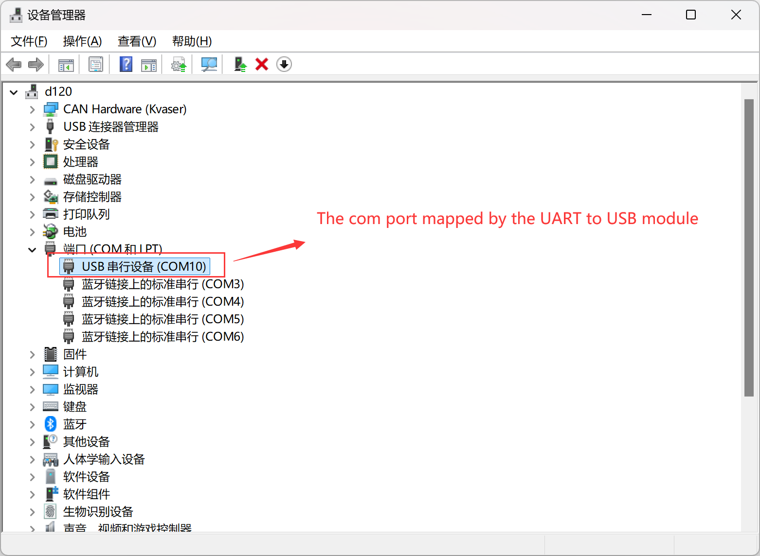
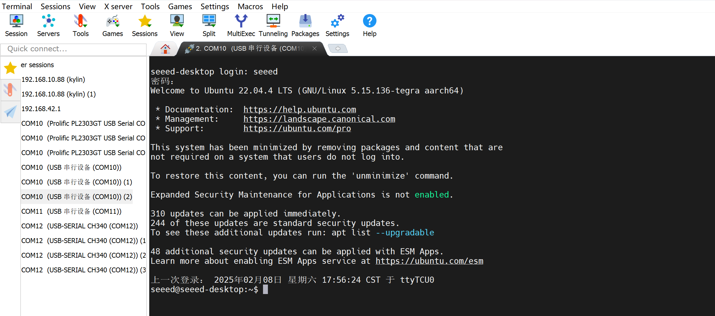
Open MobaXterm on PC, click on “Session,” and then click “Serial.” Select the COM port based on the one mapped in the “Device Manager”, and set the baud rate to 115200.
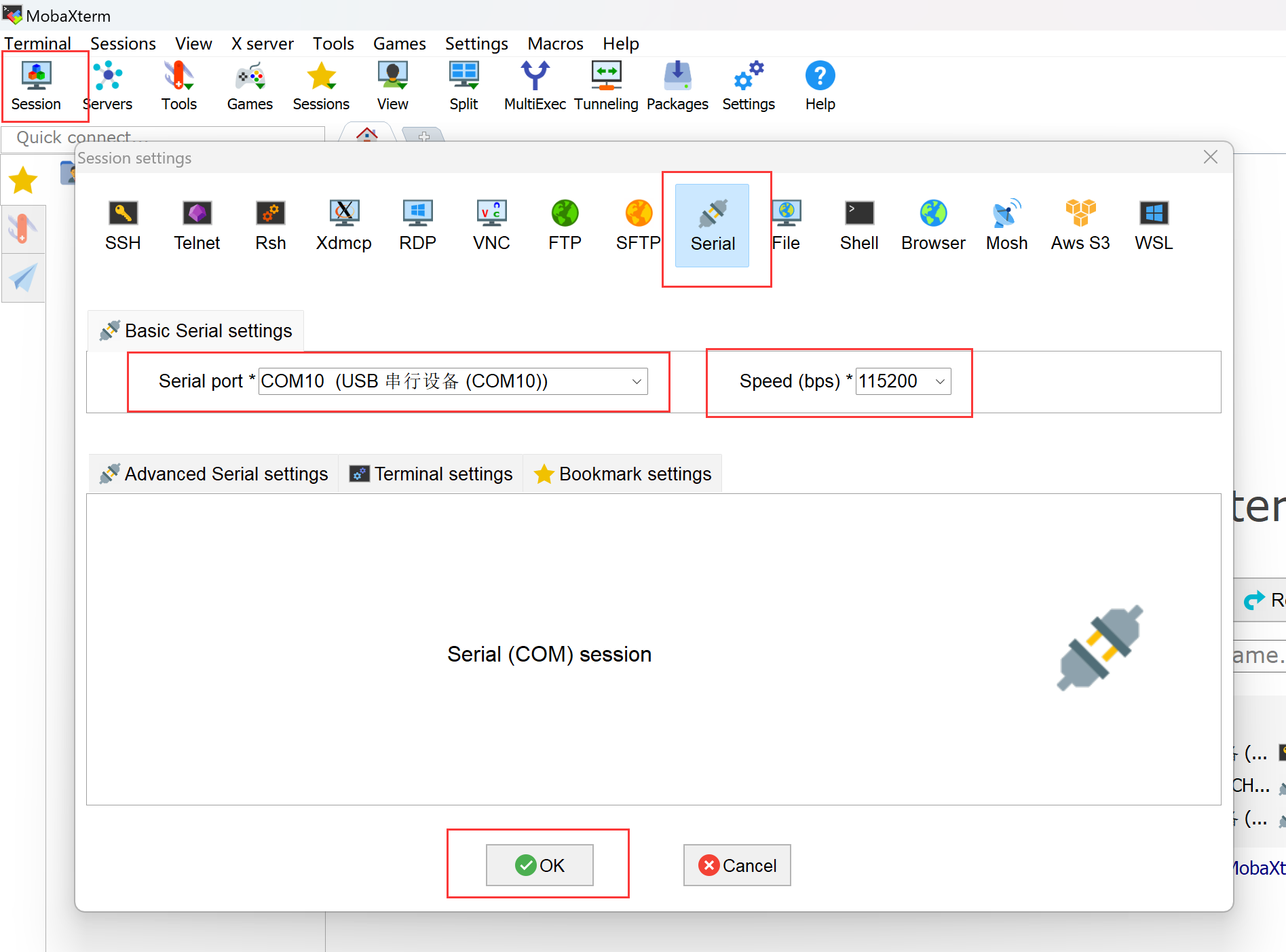
After entering the username and password, you will log in to the terminal of the reComputer Mini via UART-DEBUG.
RTC
The reComputer Mini features RTC interfaces, providing accurate timekeeping even when the system is powered off.
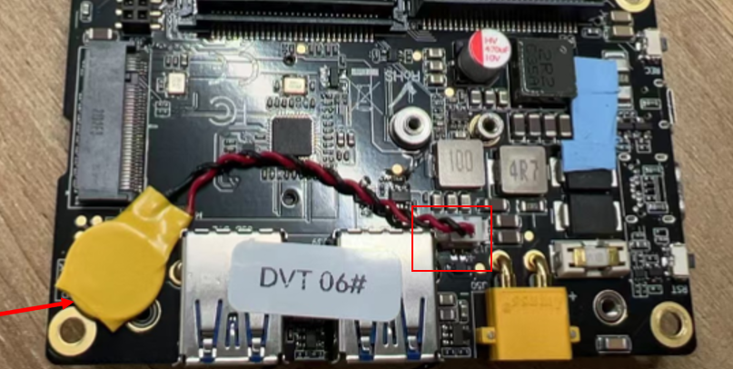
Connect a 3V CR2032 coin cell battery with JST connector to the 2-pin 1.25mm JST socket on the board.
FAN
The onboard fan interface of the reComputer Mini is managed by the nvfancontrol daemon, which adaptively adjusts the fan speed based on the operating status of the Jetson module. We can configure the working mode of the daemon through its configuration file /etc/nvfancontrol.conf.
For more information, please check here.
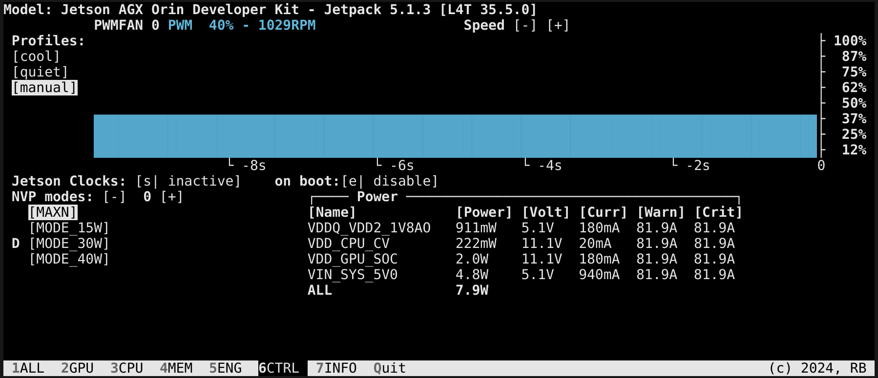
Additionally, we can manually set the fan speed using the jtop tool.
You can enter the following command in the terminal to install jtop.
sudo apt update
sudo apt install python3-pip -y
sudo pip3 install jetson-stats
Then reboot your reComputer Mini:
sudo reboot
After installing jtop, you can lanch it in terminal:
jtop
CAN
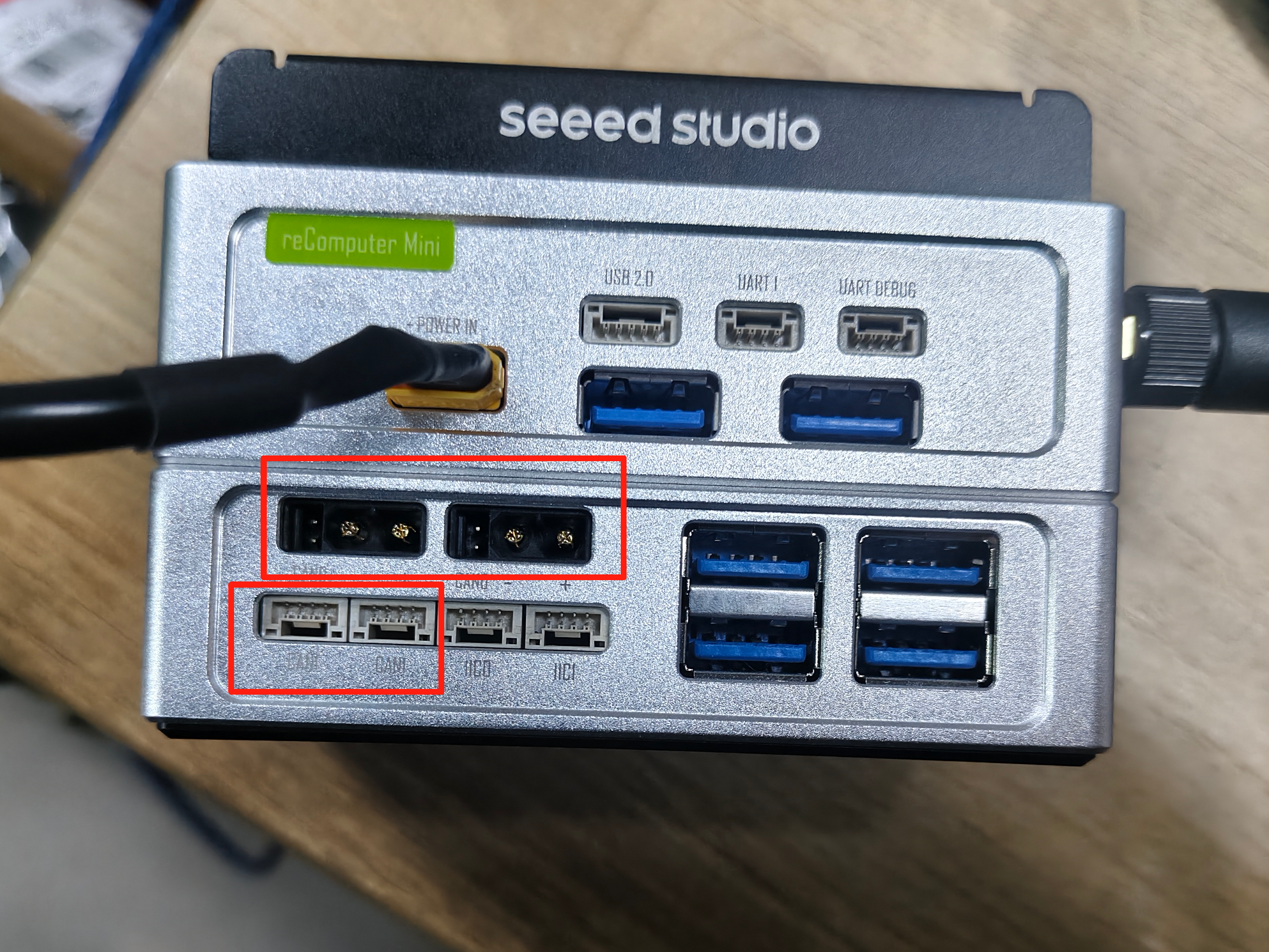
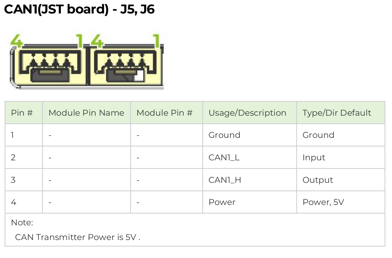
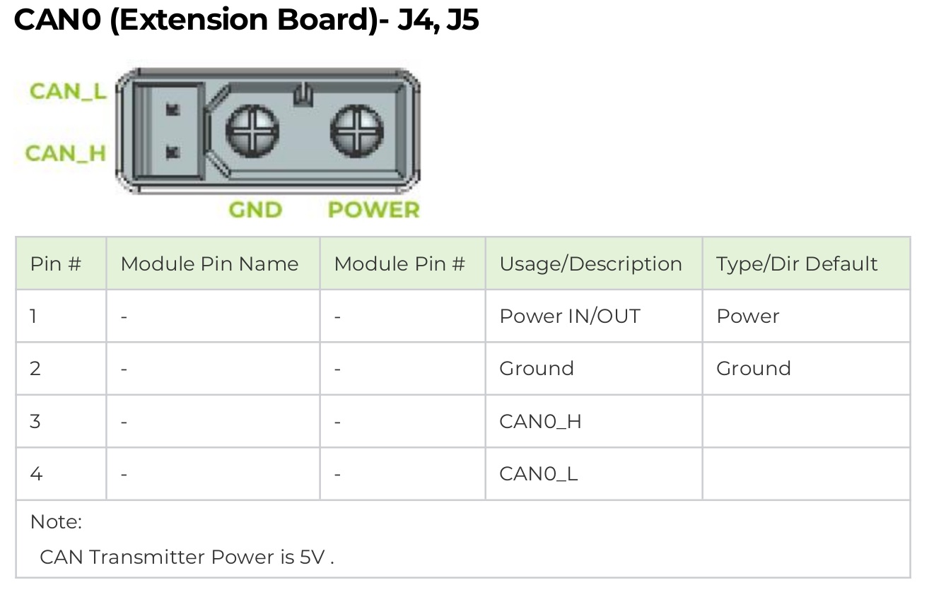
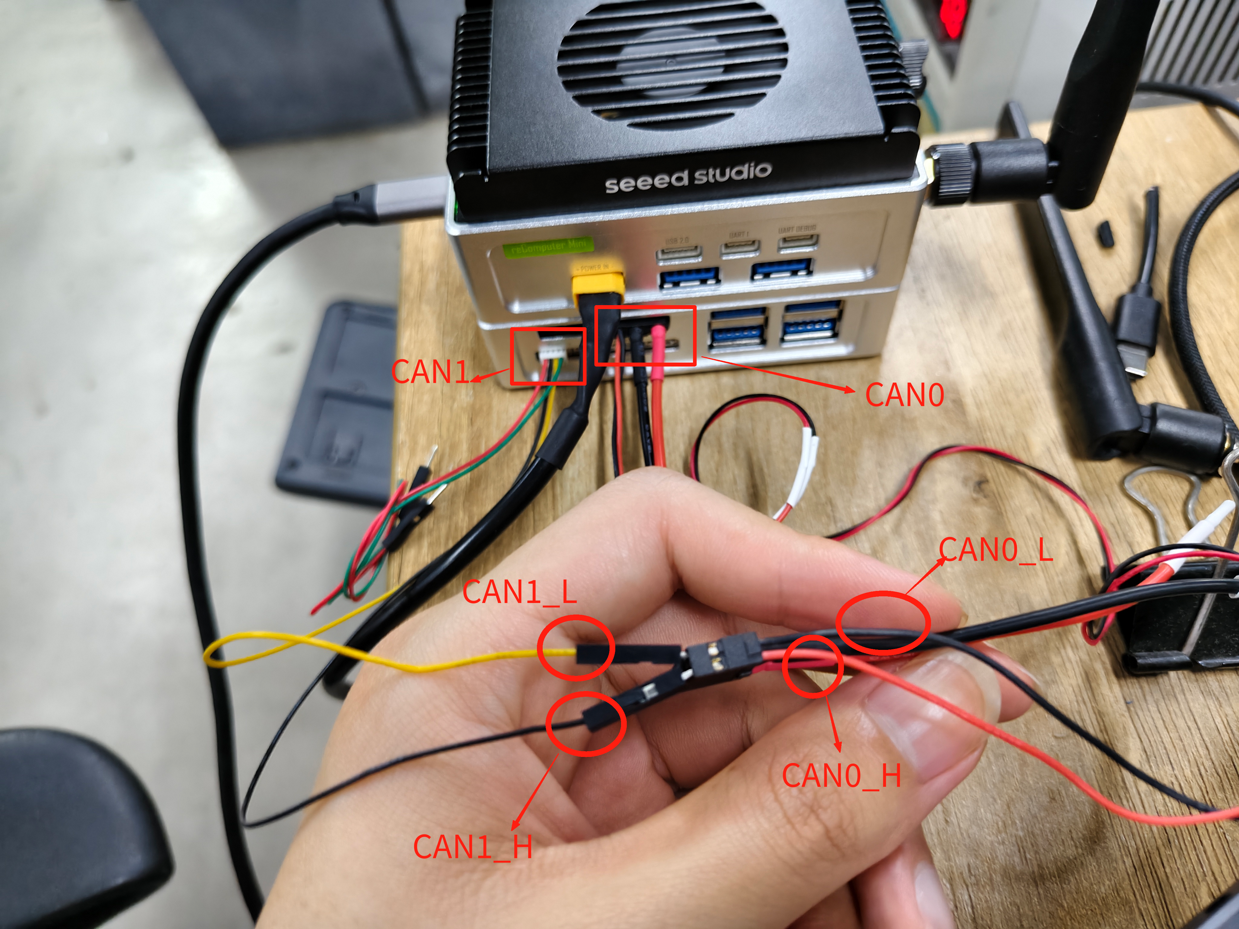
The reComputer mini features two CAN interfaces, with four external CAN interfaces on the expansion board. CAN0 consists of two XT30 connectors (2+2), while CAN1 consists of two 4-pin GH-1.25 connectors.
CAN0/CAN1 Communication
Hardware Connection
In the datasheet, you can find the wiring diagram for the CAN0/CAN1 interface as shown below:
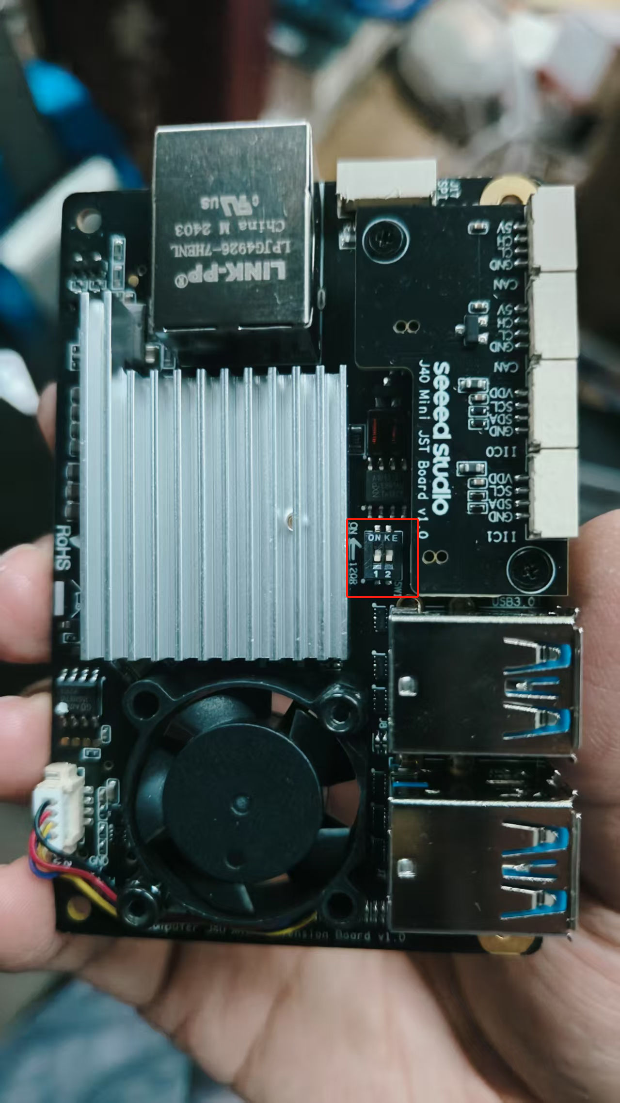
Before using CAN0 and CAN1, please remove the bottom cover and set both 120Ω termination resistors to the ON position.
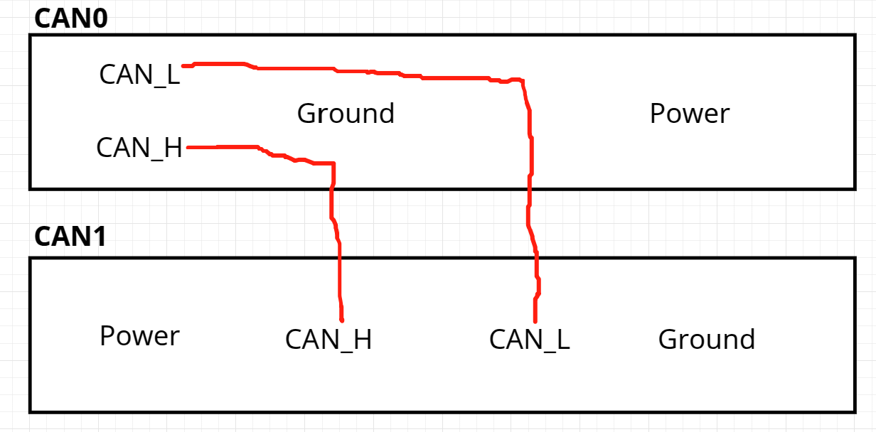
Here, we will demonstrate sending data continuously from CAN0 to CAN1 at a baud rate of 125 kbps for 30 seconds. First, as shown in the figure below, connect the signal lines of CAN0 to those of CAN1. Specifically, connect CAN0_H to CAN1_H and CAN0_L to CAN1_L.
Usage Instruction
After completing the hardware connections.
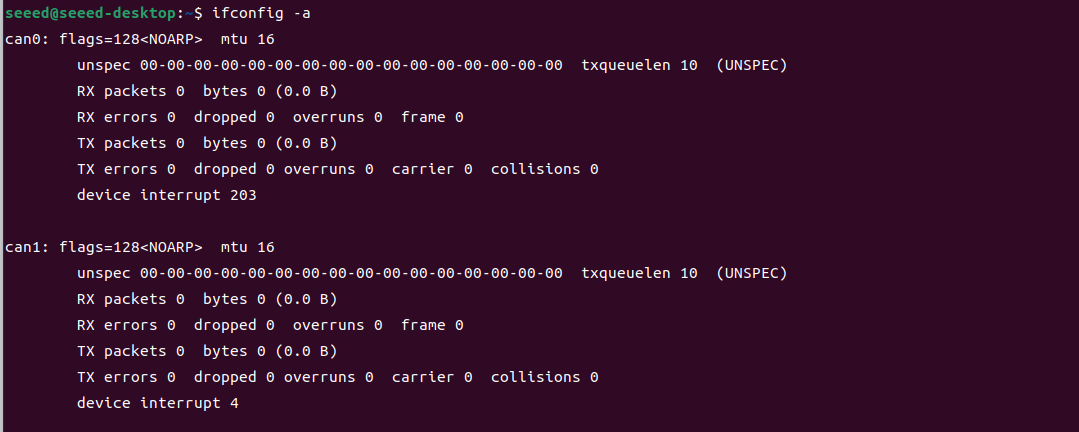
Enter the following command in the terminal to view the device names mapped to CAN0 and CAN1:
ifconfig -a
Here, can0 corresponds to the CAN0 interface, and can1 corresponds to the CAN1 interface.
Install can-utils in terminal:
sudo apt-get update
sudo apt-get install can-utils
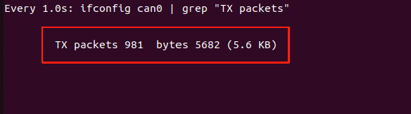
Open a Terminal 1 and enter the following command to monitor the number of bytes of data sent from can0:
watch -n 1 'ifconfig can0 | grep "TX packets"'
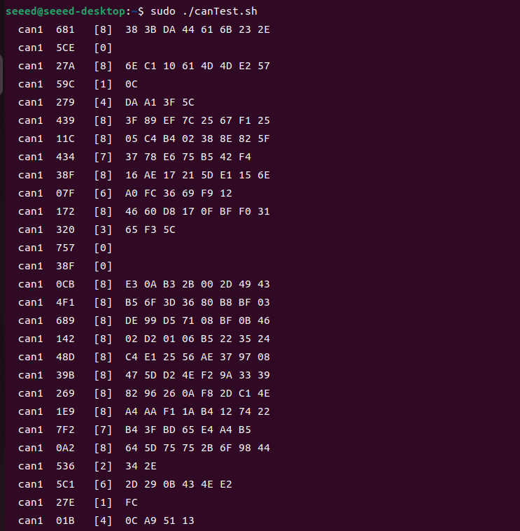
Open a Terminal 2 . Pull the script for testing CAN communication from GitHub and run it:
git clone https://github.com/jjjadand/Mini_CANtest.git
cd Mini_CANtest
sudo ./canTest.sh
By observing the two terminals, you can see that in Terminal 1, the number of bytes sent from CAN0 is increasing.
Terminal 2 will print the data received by CAN1 from CAN0.
You need to enable CAN, before using it in your program. run this command in terminal:
sudo gpioset --mode=wait 0 106=0 #enable CAN1
sudo gpioset --mode=wait 0 43=0 #enable CAN0
CAN0 Power Output
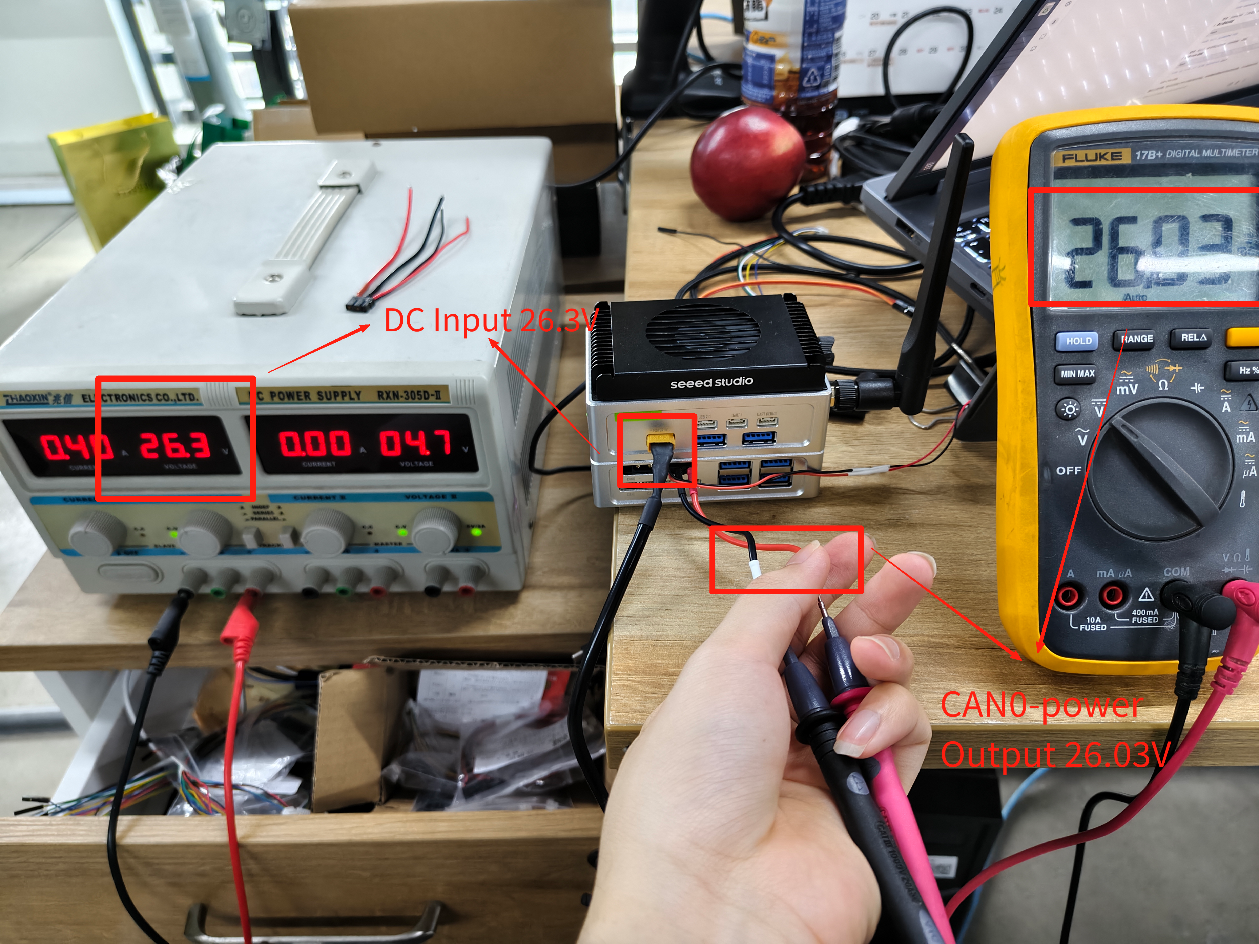
The output voltage of CAN0-PPOWER theoretically equals the current DC input voltage of the reComputer Mini. The DC input voltage range is 12-54V. Therefore, the power output range of CAN0 XT30 (2+2) is also 12-54V.
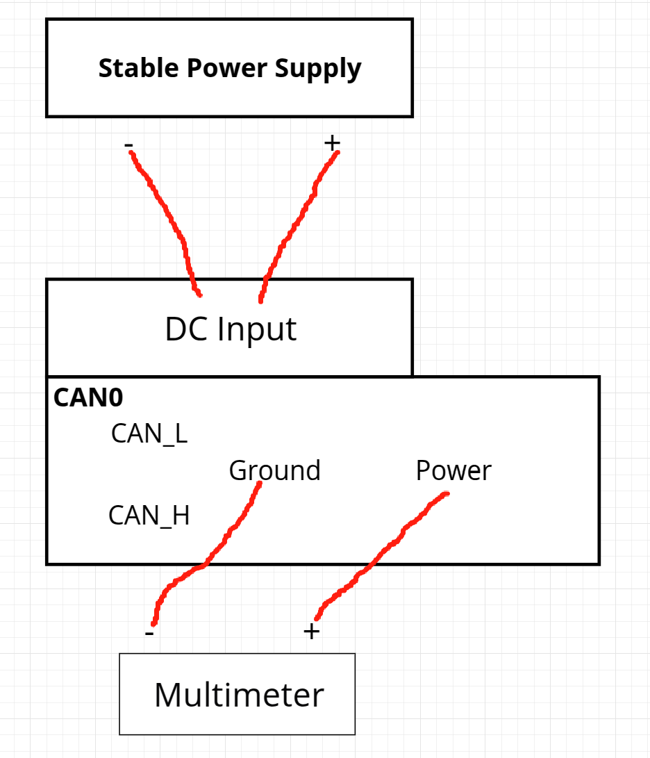
We will supply different voltages to the DC input and then measure the output voltage of CAN0-PPOWER. Use a stable power supply and a multimeter, and connect according to the diagram below.
When the DC input is 26.3V, the multimeter measures the CAN0-POWER output to be 26.03V.
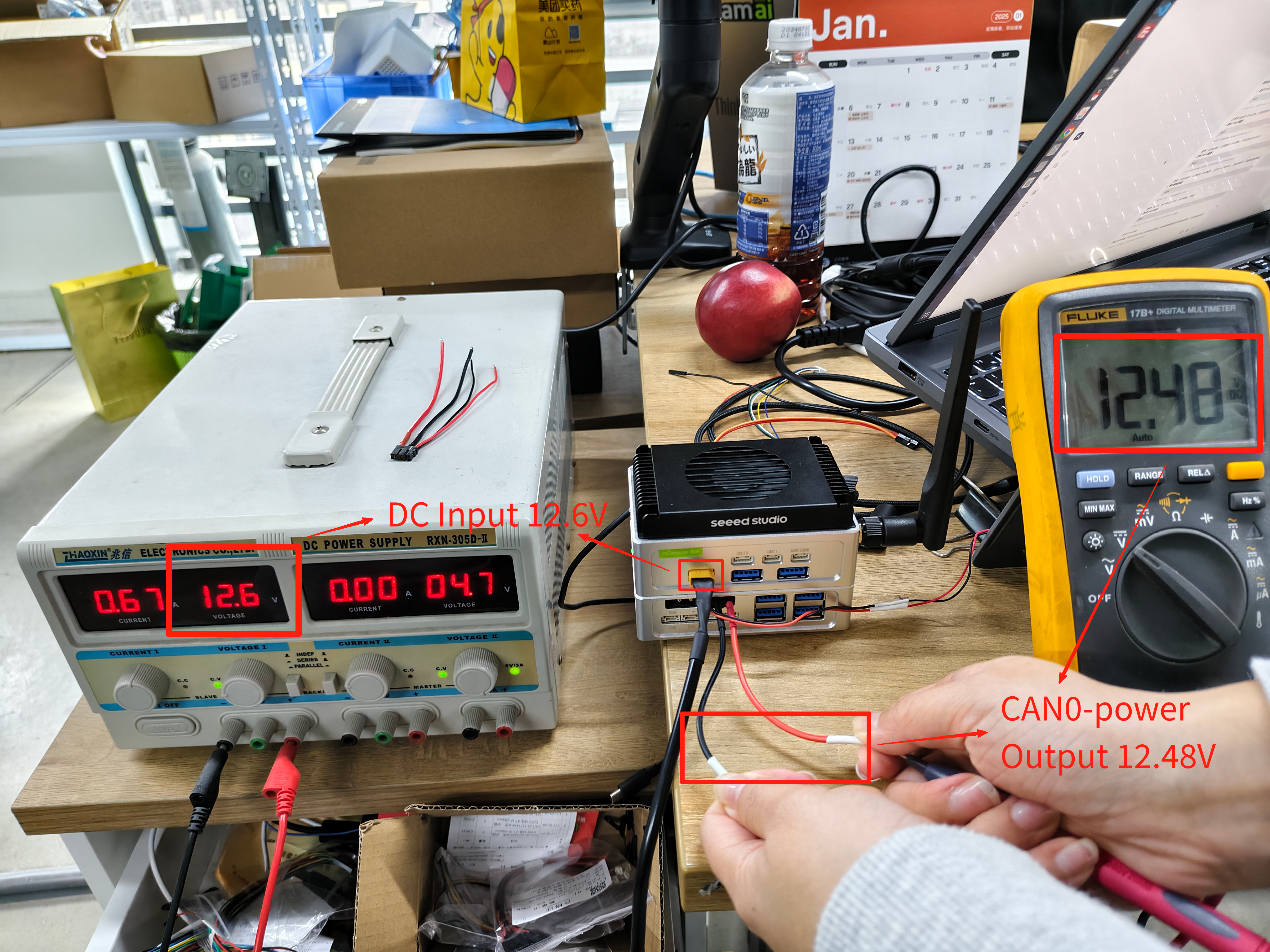
When the DC input is 12.6V, the multimeter measures the CAN0-POWER output to be 12.48V.
Based on the test results above, it can be seen that the output of CAN0-POWER is close to the DC input. If you want to know more details, you can refer to the schematic.
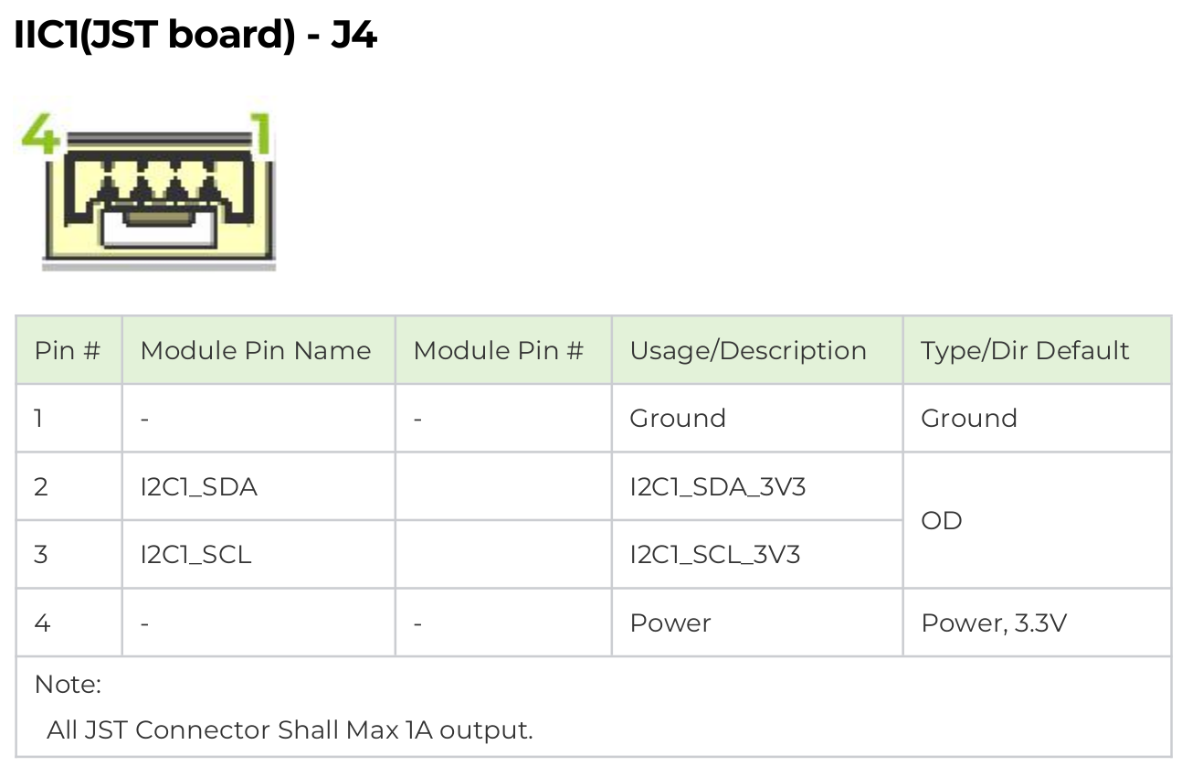
I2C
Hardware Connection
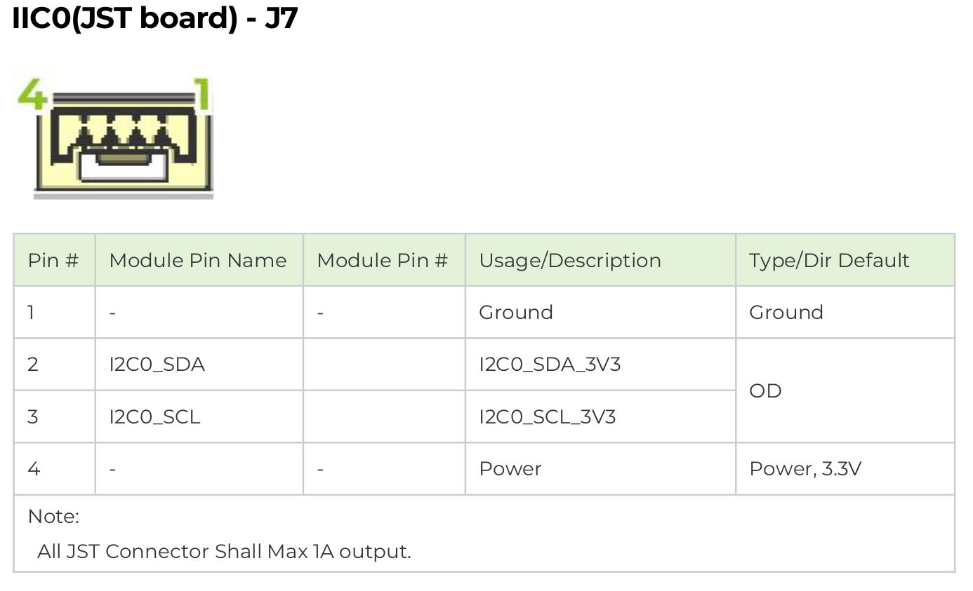
The expansion board of the reComputer features two 4-pin GH-1.25 IIC interfaces, IIC0 and IIC1.
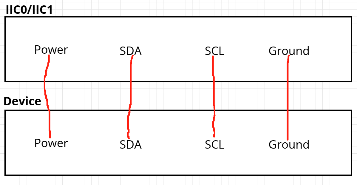
In the datasheet, you can find the wiring diagram for the IIC0/IIC1 4-pin GH-1.25 interface as shown below:
Select an IIC interface device for testing; the choice is up to you. Here, an IIC interface sensor is connected to I2C0/I2C1 for testing purposes.
The testing process here involves scanning for the addresses of externally connected devices on IIC0/IIC1.
Usage Instruction
After completing the hardware connections.
We need to install the tools for IIC testing. Enter the following in the terminal before scanning device:
sudo apt update
sudo apt-get install i2c-tools
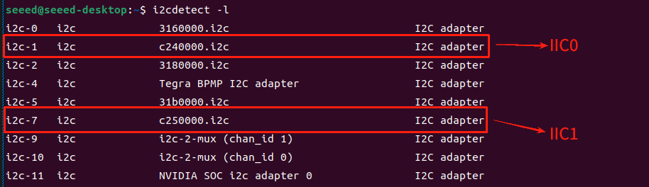
Then, enter the following command in the terminal to view the mapped names on the IIC bus.
i2cdetect -l
The external interface IIC0-J7 on the expansion board corresponds to i2c-1 i2c c240000.i2c, and the external interface IIC1-J7 corresponds to i2c-7 i2c c250000.i2c.
After connecting the external I2C device and setting its address, open two different terminals and enter the following commands to scan on I2C0 and I2C1:
sudo i2cdetect -y -r 1
sudo i2cdetect -y -r 7
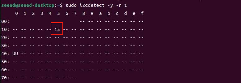
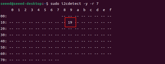
We can see that the device connected to I2C0 is set to address 0x15, and the device connected to I2C1 is set to address 0x19.
SPI
Hardware Connection
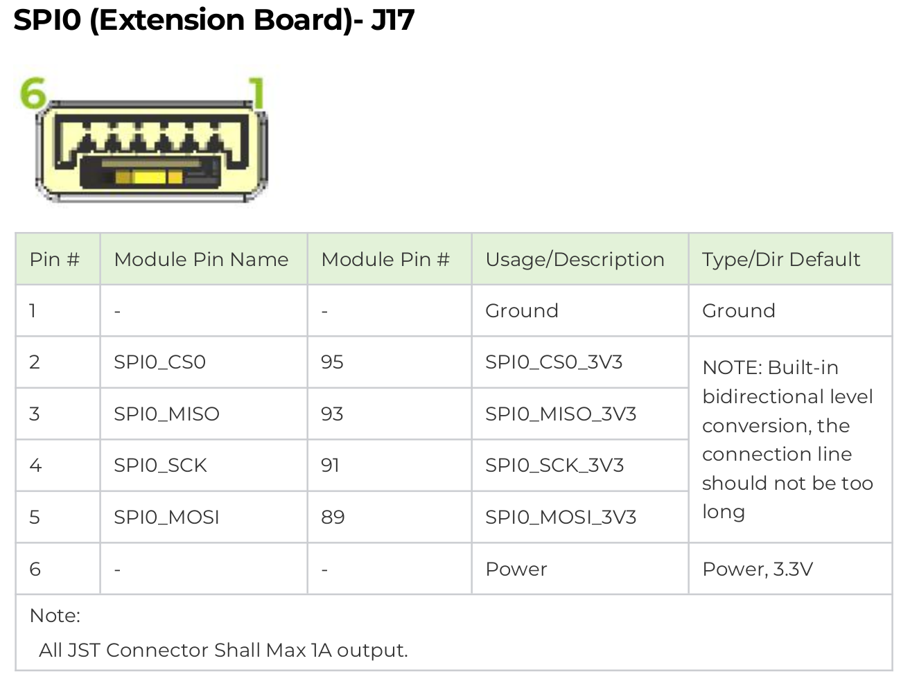
The expansion board of the reComputer features a 6-pin GH-1.25 external SPI interface.
In the datasheet, you can find the wiring diagram for the SPI 6-pin GH-1.25 interface as shown below:
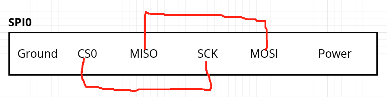
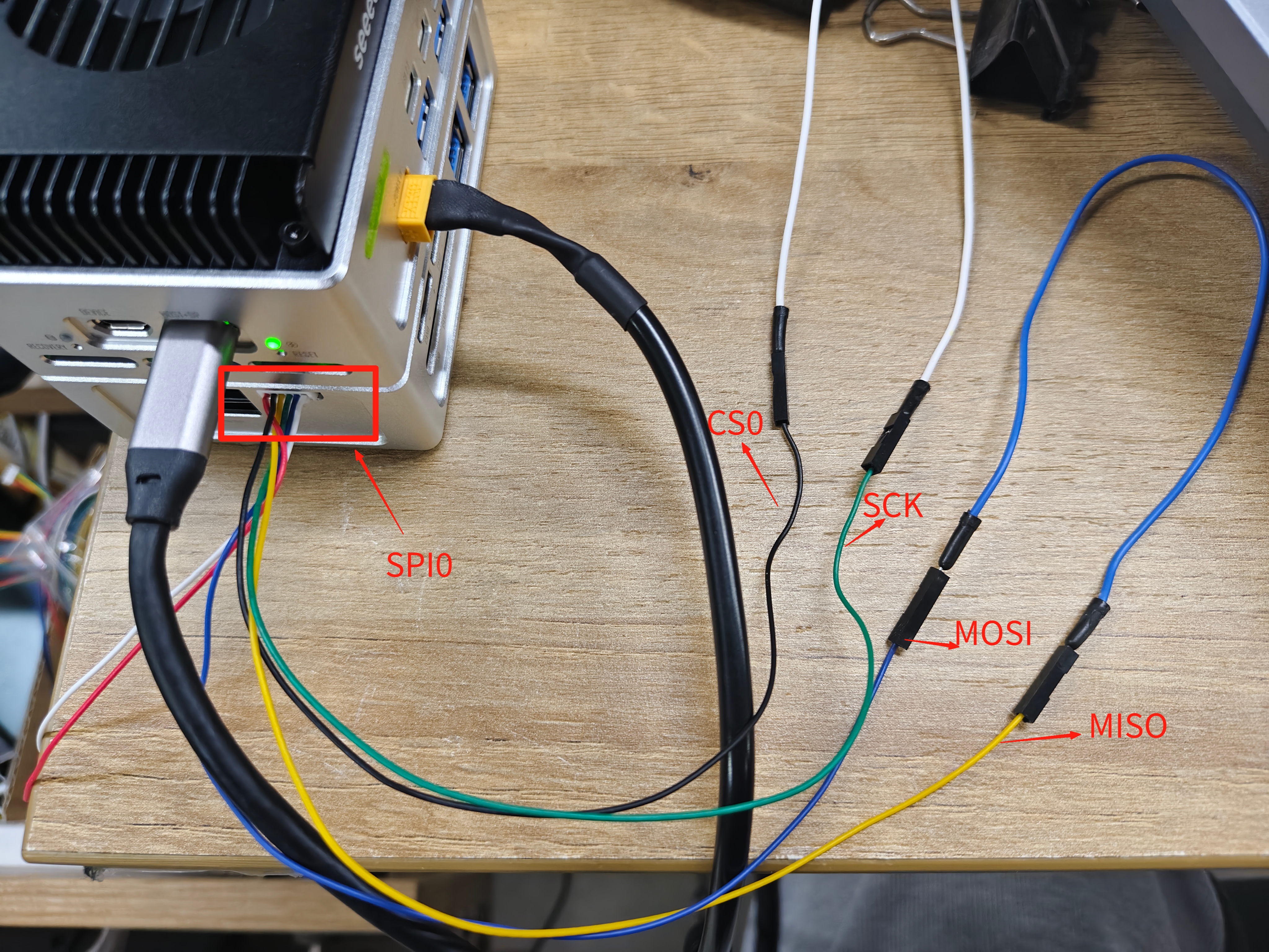
If you do not use an external SPI-to-USB module, you can self-connect the 6-pin GH-1.25 SPI interface to test data transmission and reception. Connect MOSI to MISO, and CS0 to SCK. The wiring diagram is as follows:
Usage Instruction
After completing the hardware connections.
Then, pull the code for SPI testing from GitHub and compile it:
git clone https://github.com/rm-hull/spidev-test
cd spidev-test
gcc spidev_test.c -o spidev_test
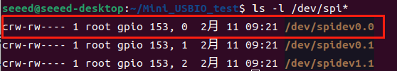
Enter the following command in the terminal to view the device name mapped by SPI. For example, /dev/spidev0.0 corresponds to SPI0 on the Extension Board (J17).
ls -l /dev/spi*
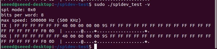
Enter the following command in the terminal to run the program for SPI testing:
sudo ./spidev_test -v
You can observe the data being transmitted and received on SPI0 on the Extension Board (J17).
Resources
Tech Support & Product Discussion
Thank you for choosing our products! We are here to provide you with different support to ensure that your experience with our products is as smooth as possible. We offer several communication channels to cater to different preferences and needs.