Robotics J401 carrier board Hardware and Getting Started
The reComputer Robotics J401 is a compact, high-performance edge AI carrier board designed for advanced robotics. Compatible with NVIDIA Jetson Orin Nano/Orin NX modules in Super/MAXN mode, it delivers up to 157 TOPS of AI performance. Equipped with extensive connectivity options—including dual Gigabit Ethernet ports, M.2 slots for 5G and Wi-Fi/BT modules, 6 USB 3.2 ports, CAN, GMSL2 (via optional expansion), I2C, and UART—it serves as a powerful robotic brain capable of processing complex data from various sensors. Pre-installed with JetPack 6 and Linux BSP, it ensures seamless deployment.
Supporting frameworks like NVIDIA Isaac ROS, Hugging Face, PyTorch, and ROS 2/1, the reComputer Robotics J401 bridges large language model-driven decision-making with physical robotics control, such as motion planning and sensor fusion. Ideal for the rapid development of autonomous robots, it accelerates time-to-market with ready-to-use interfaces and optimized AI frameworks.

reComputer Jetson Robotics J401 Carrier Board overview
| Top View |
|---|
 |
| Top View |
 |
| Top View |
 |
Part List
- reComputer Robotics J401 Carrier Board x 1
- Power Supply and JST expansion board x 1
- XT30 to DC cable x 1
- USB Cable, Type A to Type C x 1
- Heat Sink for expansion board x 1
- Stud(M3*30) x 5
- M3 Hexagon nut x 5
- Screw(CM2.5*L.4) for Jetson Module and M.2 Key M x3
- Screw(CM2*3.0) for M.2 Key E x1
- Stud(M2*2.0) for M.2 Key B x1
- Screw(CM3*4.0) for M.2 Key B x1
- User Manual x 1
1.Please design a robust heat dissipation solution according to the Thermal Design Guide, when in high voltage power supply and operating temperature. 2.Please attach heat sink for module for better performance. 3.During the operation with high voltage input and high load, please do not touch the heat sink to prevent scalding. 4.Power Adapter Recommendation for Validation, please use the power adapter recommended on the Seeed official website.
- 19V/4.74A 5525 Barrel Jack Power Adapter
- Ensure maximum power consumption requirements are met. 2.AC Power Cord Compatibility
- Purchase region-specific AC cloverleaf power cords according to your location. 3.Accessory Compatibility
- Use only officially recommended accessories (e.g., wireless modules, cameras, peripherals) for optimal performance and compatibility.
Specification
Carrier Board Specifications
| Category | Item | Details |
|---|---|---|
| Storage | M.2 KEY M PCIe | 1x M.2 KEY M PCIe (M.2 NVMe 2280 SSD 128G included) |
| Networking | M.2 KEY E | 1x M.2 Key E for WiFi/Bluetooth module |
| M.2 KEY B | 1x M.2 Key B for 5G module | |
| Ethernet | 2x RJ45 Gigabit Ethernet | |
| I/O | USB | 6x USB 3.2 Type-A (5Gbps); 1x USB 3.0 Type-C (Host/DP 1.4); 1x USB 2.0 Type-C (Device Mode/Debug) |
| Camera | 1x 4 in 1 GMSL2 (mini fakra) (optional board) | |
| CAN | 2x CAN0 (XT30(2+2)); 3x CAN1 (4-Pin GH 1.25 Header) | |
| Display | 1x DP1.4 (Type C Host) | |
| UART | 1x UART 4-Pin GH 1.25 Header | |
| I2C | 2x I2C 4-Pin GH 1.25 Header | |
| Fan | 1x 4-Pin Fan Connector (5V PWM); 1x 4-Pin Fan Connector (12V PWM) | |
| Extension Port | 1x Camera Expansion Header (for GMSL2 board) | |
| RTC | 1x RTC 2-pin; 1x RTC Socket | |
| LED | 3x LED (PWR, ACT, and User LED) | |
| Pinhole Button | 1x PWR; 1x RESET | |
| DIP Switch | 1x REC | |
| Antenna Hole | 5x Antenna Hole | |
| Power | 19-54V XT30(2+2) (XT30 to 5525 DC Jack Cable included) | |
| Jetpack Version | Jetpack 6 | |
| Mechanical | Dimensions (W x D x H) | 115mm x 115mm x 38mm |
| Weight | 200g | |
| Installation | Desk, Wall-mounting | |
| Operating Temperature | -20℃~60℃ (25W Mode); -20℃~55℃ (MAXN Mode); (with reComputer Robotics heat sink with fan) | |
| Warranty | 2 Years | |
| Certification | RoHS, REACH, CE, FCC, UKCA, KC | |
Flash JetPack OS
Supported Module
- NVIDIA® Jetson Orin™ Nano Module 4GB
- NVIDIA® Jetson Orin™ Nano Module 8GB
- NVIDIA® Jetson Orin™ NX Module 8GB
- NVIDIA® Jetson Orin™ NX Module 16GB
Prerequisites
- Ubuntu host PC
- Robotics J401 Carrier Board
- NVIDIA® Jetson Orin™ Nano/NX Module
- Nano/NX Module Active Fan
- NVMe M.2 2280 Internal SSD
- USB Type-C data transmission cable
We recommend that you use physical ubuntu host devices instead of virtual machines. Please refer to the table below to prepare the host machine.
| JetPack Version | Ubuntu Version (Host Computer) | ||
| 18.04 | 20.04 | 22.04 | |
| JetPack 6.x | ✅ | ✅ | |
Prepare the Jetpack Image
Here, we need to download the system image to our Ubuntu PC corresponding to the Jetson module we are using:
| Jetpack Version | Jetson Module | GMSL | Download Link1 | SHA256 |
|---|---|---|---|---|
| 6.2 | Orin Nano 4GB | ✅ | Download | c63d1219531245abecc7bbdcafc73d3 4f75547454c7af85de40f08396a87e5ee |
| Orin Nano 8GB | ✅ | Download | 5d1f3cd28eb44ca60132c87ccce5aca f806ee945b486df9061a34de73fbb582b | |
| Orin NX 8GB | ✅ | Download | e7f0c8e6b578d411f81122879f92c76 66adfada5ed493a4cc458dc169ca8c1b7 | |
| Orin NX 16GB | ✅ | Download | b08cbdad8ab6e50222146d3175a9d2 627d499bf1d67cfaf69cc737b5bfa9e33a |
The Jetpack6 image file is approximately 14.2GB in size and should take around 60 minutes to download. Please kindly wait for the download to complete.
To verify the integrity of the downloaded firmware, you can compare the SHA256 hash value.
On an Ubuntu host machine, open the terminal and run the command sha256sum <File> to obtain the SHA256 hash value of the downloaded file. If the resulting hash matches the SHA256 hash provided in the wiki, it confirms that the firmware you downloaded is complete and intact.
Enter Force Recovery Mode
Before we can move on to the installation steps, we need to make sure that the board is in force recovery mode.
Step-by-Step
Step 1. Switch the switch to the RESET mode.

Step 2. Power up the carrier board by connecting the power cable.
Step 3. Connect the board to the Ubuntu host PC with a USB Type-C data transmission cable.
Step 4. On the Linux host PC, open a Terminal window and enter the command lsusb. If the returned content has one of the following outputs according to the Jetson SoM you use, then the board is in force recovery mode.
- For Orin NX 16GB: 0955:7323 NVidia Corp
- For Orin NX 8GB: 0955:7423 NVidia Corp
- For Orin Nano 8GB: 0955:7523 NVidia Corp
- For Orin Nano 4GB: 0955:7623 NVidia Corp
The below image is for Orin Nano 8GB

Flash to Jetson
Step 1: Extract the downloaded image file:
cd <path-to-image>
sudo tar xpf mfi_xxxx.tar.gz
# For example: sudo tar xpf mfi_recomputer-robo-orin-nano-8g-j401-gmsl-6.2-36.4.3-2026-02-06.tar.gz
Step 2: Execute the following command to flash jetpack system to the NVMe SSD:
cd mfi_xxxx
# For example: cd mfi_recomputer-orin-robotics-j401
sudo ./tools/kernel_flash/l4t_initrd_flash.sh --flash-only --massflash 1 --network usb0  --showlogs
You will see the following output if the flashing process is successful
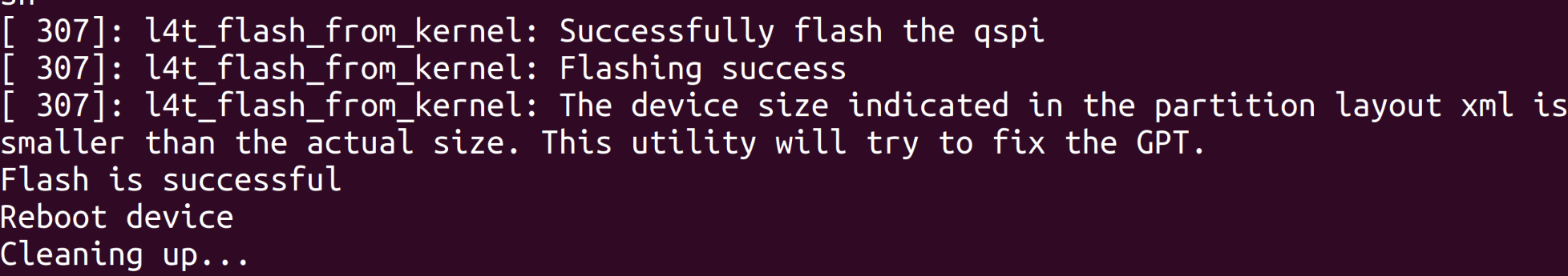
The flash command may run for 2-10 minutes.
Step 3: Connect the Robotics J401 to a display use the PD to HDMI adapter to connect to a display that supports HDMI input, or directly connect to a display that supports PD input using the PD cable, and finish the initial configuration setup:
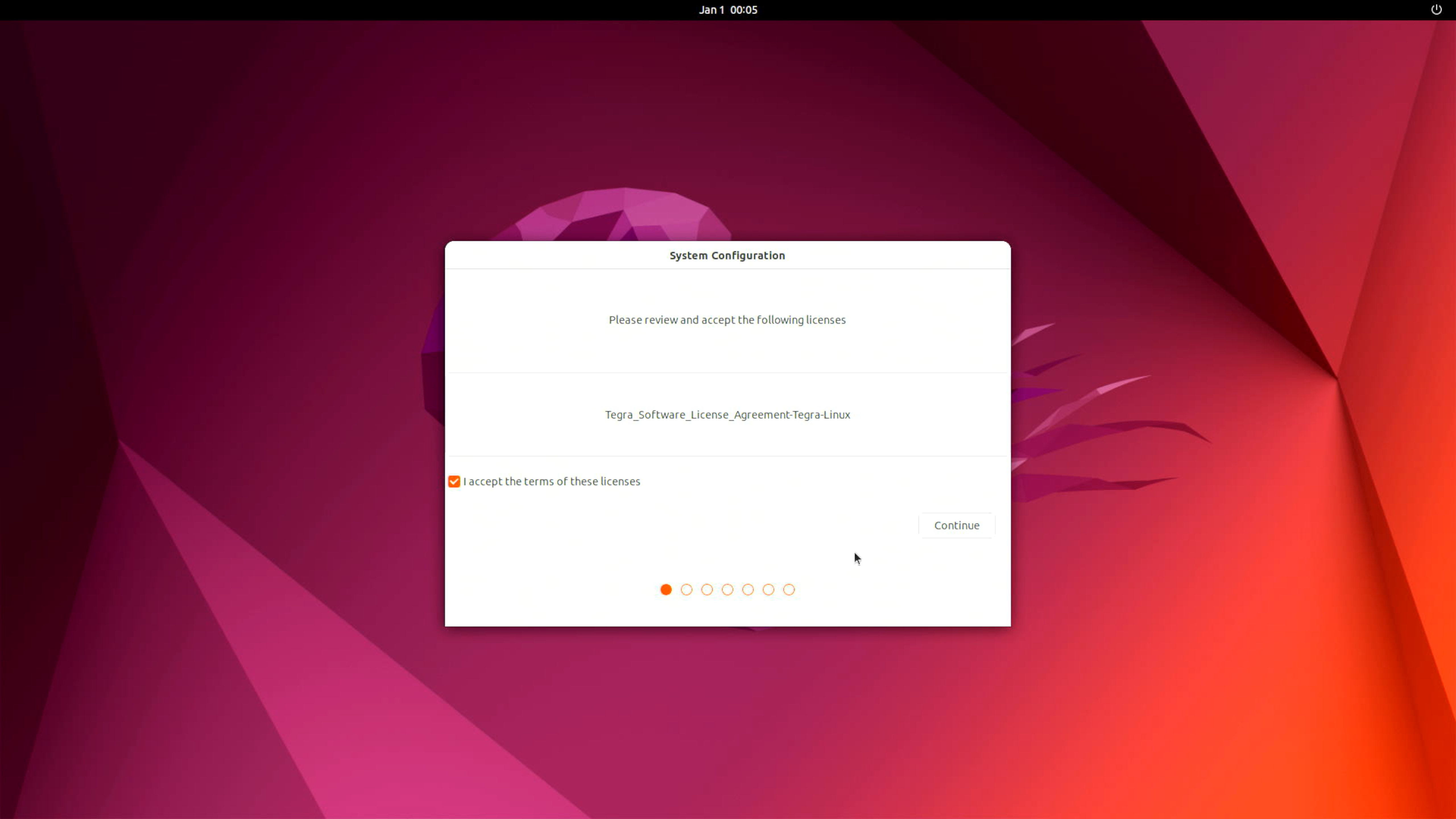
Please complete the System Configuration according to your needs.
Interfaces Usage
The following will introduce the various interfaces of the Robotics J401 board and how to use them.
M.2 Key M
M.2 Key M is designed for high-speed NVMe SSDs, providing ultra-fast data transfer for robotics applications.
Supported SSD are as follows
- 128GB NVMe M.2 PCle Gen3x4 2280 Internal SSD
- 256GB NVMe M.2 PCle Gen3x4 2280 Internal SSD
- 512GB NVMe M.2 PCle Gen3x4 2280 Internal SSD
- 1TB NVMe M.2 PCle Gen3x4 2280 Internal SSD
- 2TB NVMe M.2 PCle Gen3x4 2280 Internal SSD
Hardware Connection

Usage Instruction
Open the terminal in Jetson device and enter the following command to test the SSD's read and write speed.
#You need to create a blank test file first
sudo touch /ssd/test
dd if=/dev/zero of=/home/seeed/ssd/test bs=1024M count=5 conv=fdatasync

Please run sudo rm /home/seeed/ssd/test command to delete the cache files after the test is complete.
M.2 Key B
M.2 Key B slot for 5G Module expansion, enabling high-speed cellular connectivity for robotics and edge AI scenarios.
Hardware Connection

Usage Instruction
Step 1. Check Hardware Recognition
lsusb
This command displays a list of all USB devices connected to the system, along with their manufacturer (ID), type, and other information. For example, the output might show a device from Quectel Wireless Solutions Co., Ltd. EM12-G, indicating that the 5G module is present.

Step 2. Confirm Driver Loading It's essential to ensure that the option driver, which is required for the 5G module, is loaded. We can use the lsmod command to check.
lsmod | grep option
If the option driver is loaded successfully, relevant information about the driver will be displayed in the output.

Step 3. Configure ModemManager ModemManager is a tool for managing modem devices, and it needs to be installed and restarted.
sudo apt install modemmanager
sudo systemctl restart ModemManager
The apt install command is used to install the ModemManager package, while systemctl restart restarts the ModemManager service to ensure that the new settings take effect.
Step 4. Verify Module Identification We can use the mmcli -L command to check if the ModemManager can correctly identify the 5G module.
mmcli -L
If the 5G module is recognized, an output similar to /org/freedesktop/ModemManager1/Modem/0 will be displayed, indicating the path to the detected modem device.

Step 5. Set the APN APN (Access Point Name) is crucial for connecting a mobile device to the network.We'll use the nmcli command to create a bearer profile. Taking China Mobile as an example, we can create a configuration file with the following commands:
sudo nmcli con add type gsm ifname "*" apn "CMNET" ipv4.method auto
This command adds a new GSM (Global System for Mobile Communications) type connection, specifying the APN as "CMNET" and using automatic IPv4 configuration.

Step 6. Activate the Connection After creating the bearer profile, we need to activate the connection.
sudo nmcli con up "gsm"
This command activates the GSM connection, and if successful, a confirmation message will be displayed.
Step 7. Re-verify Module Identification Run the mmcli -L command again to ensure that the module remains recognized after configuring the APN.
mmcli -L
Step 8. Check Module Status Finally, we can use the mmcli -m 0 command to view detailed information about the module, such as IP allocation, carrier, and network connection status.
mmcli -m 0
This command provides comprehensive details about the 5G module, including its manufacturer, model, supported and current network technologies, device status, and connected network operators.

M.2 Key E
The M.2 Key E interface is a standard M.2 connector primarily used for connecting wireless modules, such as Wi-Fi and Bluetooth, to expand wireless communication capabilities.
Hardware Connection

Usage Instruction
To test Wi-Fi performance, use the following command (replace the IP address with your test server):
iperf3 -c 192.168.6.191

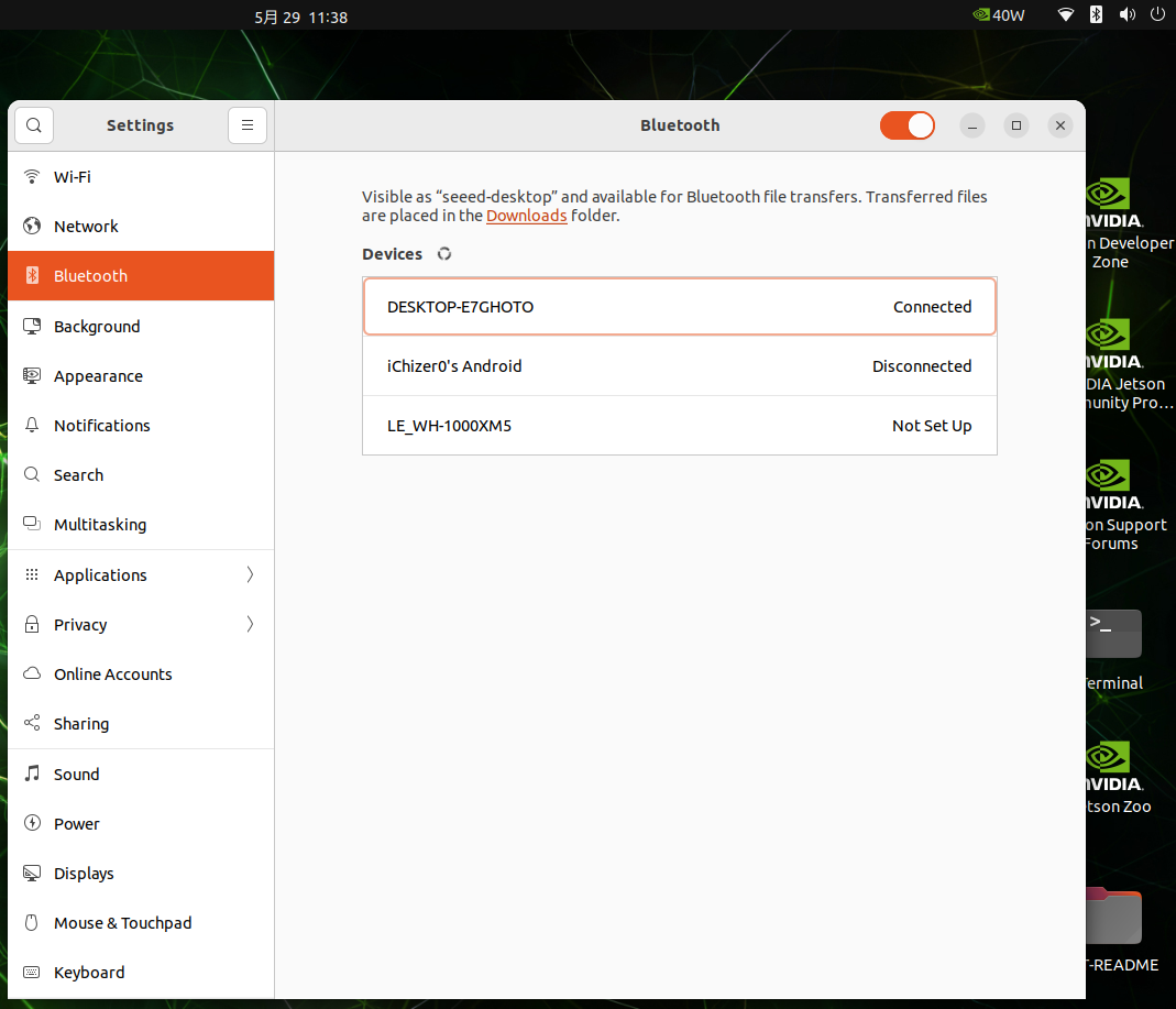
Bluetooth functionality is available via the M.2 Key E slot.
Ethernet
The Robotics j401 carrier board features 2 1Gbps RJ45 Ethernet ports for high-speed wired network connectivity.

To test Ethernet port speed, use iperf3 as follows :
iperf3 -c <server_ip> -B <bind_ip>
<server_ip> is the IP address of the iperf3 server. The client will connect to this server to perform a bandwidth test.
<bind_ip> binds the specified local IP address as the source of the test traffic.

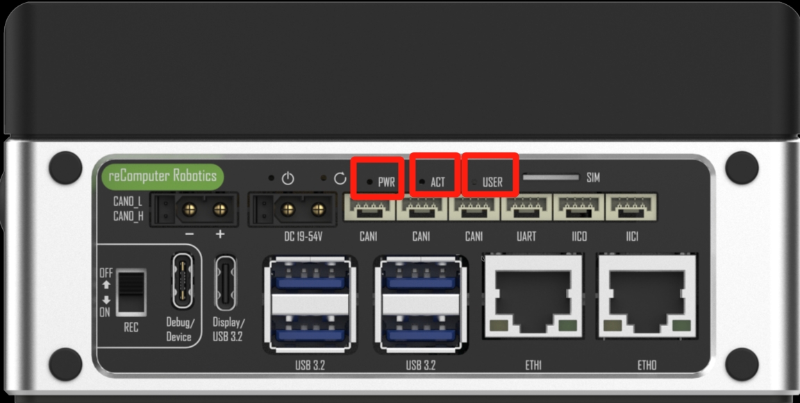
LED
The reComputer Jetson Robotics J401 features 3 LED indicators (PWR, ACT, and User LED) that provide clear status feedback for power, system activity, and user-defined functions.
Usage Instruction
The User LED is an RGB LED can display different colors to indicate various statuses, need to be defined by user.
Here is a test script to control the RGB LED:
touch rgb_test
chmod +x rgb_test
vi rgb_test
Paste the following content:
#!/bin/bash
# RED ON
gpioset --mode=time --sec=1 2 0=1
sleep 2
# RED OFF
gpioset --mode=time --sec=1 2 0=0

# Blue ON
gpioset --mode=time --sec=1 2 1=1
sleep 2
# Blue OFF
gpioset --mode=time --sec=1 2 1=0

# Green ON
gpioset --mode=time --sec=1 2 2=1
sleep 2
# Green OFF
gpioset --mode=time --sec=1 2 2=0
Run the script to test the RGB LED.

USB
The Robotics j401 carrier board is equipped with a variety of USB ports, including 6 USB 3.2 Type-A ports (5Gbps), one USB 3.0 Type-C port with DP 1.4 (Host mode), and one USB 2.0 Type-C port for device mode/debugging, offering versatile connectivity options.
USB Speed Test
Create a script to test USB device speed:
sudo vim test_usb
Paste the following content:
#!/bin/bash
sudo dd if=/dev/zero of=/dev/$1 bs=1000M count=2 conv=fdatasync
sleep 1
sudo sh -c "sync && echo 3 > /proc/sys/vm/drop_caches"
sleep 1
sudo dd if=/dev/$1 of=/dev/null bs=1000M count=2
Make the script executable:
sudo chmod +x test_usb
Run the script with your USB device name as the argument.
USB 2.0 Type-C port
Using this serial port, via the USB C data cable, you can monitor the debugging information of input and output on the PC side.
Step1. Switch the switch to the debug mode.

Step2. Connect the PC via a USB data cable, downloaded the CP210X Driver on your PC.

Step3. Connect the PC via a USB data cable, extract the downloaded file and install driver on your PC.

Step4. Open Open the Device Manager on your Windows PC and check the COM port number assigned to the reComputer Super. It should appear under "Ports (COM & LPT)" as "Silicon Labs CP210x USB to UART Bridge (COMX)", where X is the COM port number.

Step5. Open the serial port tool(Here, we use the MobaXterm tool as an example), create a new session.

Step6. Select the Serial tool.

Step7. Select corresponding serial port, set the baud rate to 115200 and click "OK".

Step8. Login your reComputer Super with the username and password.

USB Camera
Using USB camera through a USB 3.2 Type-A ports, install and run guvcview:
sudo apt-get install guvcview
guvcview -d /dev/video0

Fan
The reComputer Jetson Robotics J401 is equipped with two types of fan connectors to meet different voltage and cooling needs:
-
1x 4-Pin Fan Connector (5V PWM): Designed for low-voltage, low-power silent fans, this connector supports PWM speed control, allowing intelligent fan speed adjustment based on system temperature to improve energy efficiency and reduce noise.
-
1x 4-Pin Fan Connector (12V PWM): Compatible with standard 12V PWM fans, it also supports precise speed control, making it ideal for high-performance cooling requirements.
Hardware Connection

For more information, please check here.
Create a script to set fan speed:
cat test_fanSpeedSet
Paste the following content:
#!/bin/bash
sudo systemctl stop nvfancontrol
sleep 2
echo "000000" | sudo -S chmod 777 /sys/devices/platform/pwm-fan/hwmon/hwmon1/pwm1
echo $1 > /sys/devices/platform/pwm-fan/hwmon/hwmon1/pwm1
Note: For Jetson Nano 4G, the fan path is
/sys/devices/platform/pwm-fan/hwmon/hwmon0/pwm1.
Additionally, we can manually set the fan speed using the jtop tool.
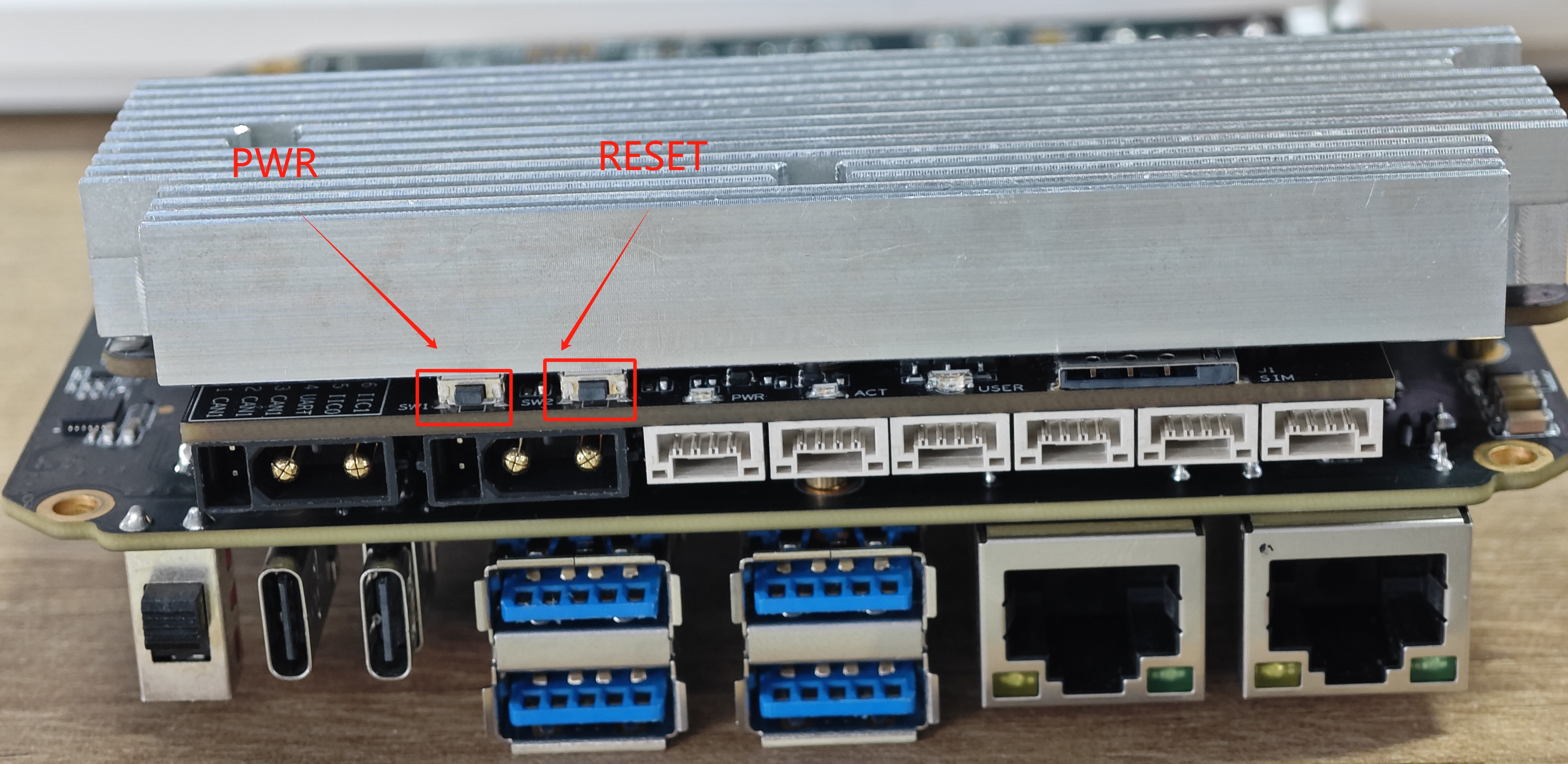
Pinhole Button
The Robotics J401 carrier board features a Pinhole Button for user interaction, including a Power (PWR) button and a Reset (RESET) button. These buttons are essential for powering the device on/off and performing system reboots, respectively.
CAN
CAN (Controller Area Network) is a robust vehicle bus standard that enables microcontrollers and devices to communicate with each other without a host computer. The Robotics J401 provides one CAN0 interface integrated into the XT30 (2+2) power connector for convenient power and data transmission.Additionally, offers 3 CAN1 interface via two standard JST 4-pin headers for flexible CAN bus connectivity.
CAN Communication
In the datasheet, you can find the wiring diagram for the CAN0/CAN1 interface as shown below:

Here we will demonstrate to you how to conduct data communication using the CAN1 interface, by utilizing the USB to CAN Analyzer Adapter.
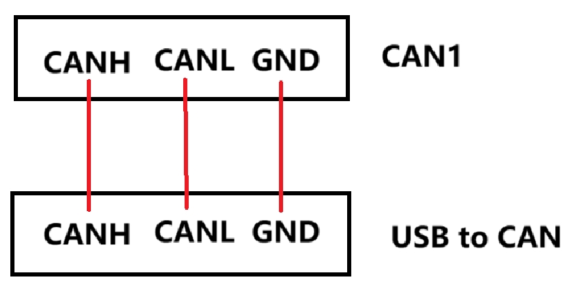
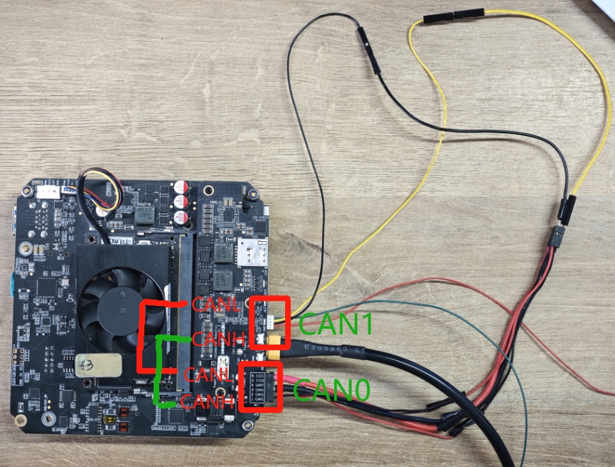
Hardware Connection
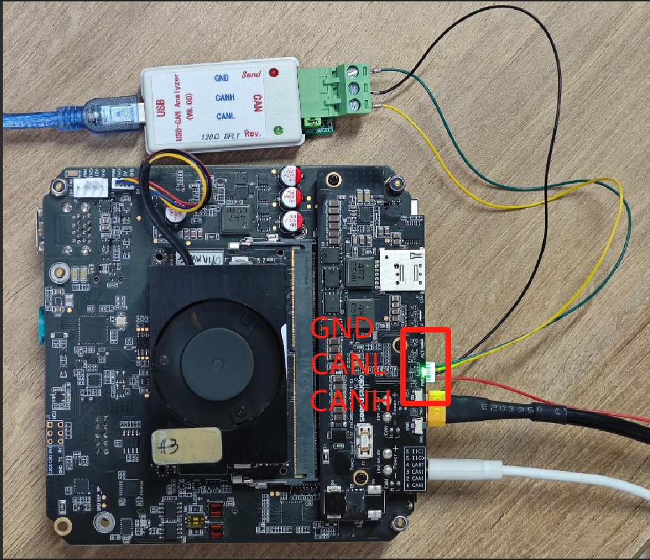
According to the connection method shown in the figure below, connect CAN1's CANL, CANH, and GND to the corresponding CANL, CANH, and GND ports of the USB to CAN tool respectively.
In our case, according to the adapter that we used, we have downloaded and installed the software which can be found here.
Step 1. Configure the CAN1 interface:
#Set the bit rate
sudo ip link set can1 type can bitrate 500000
#Enable CAN1
sudo ip link set can1 up
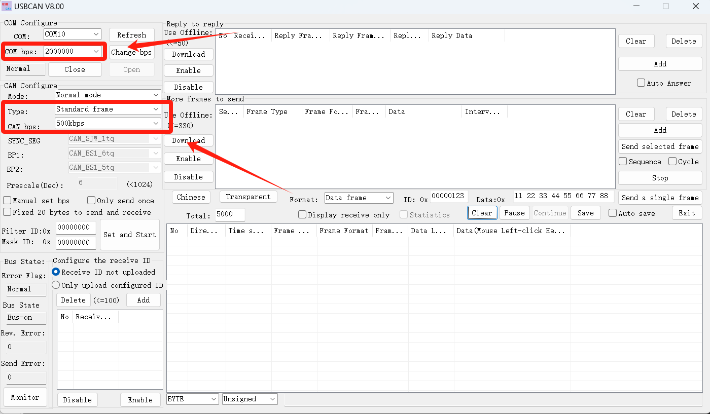
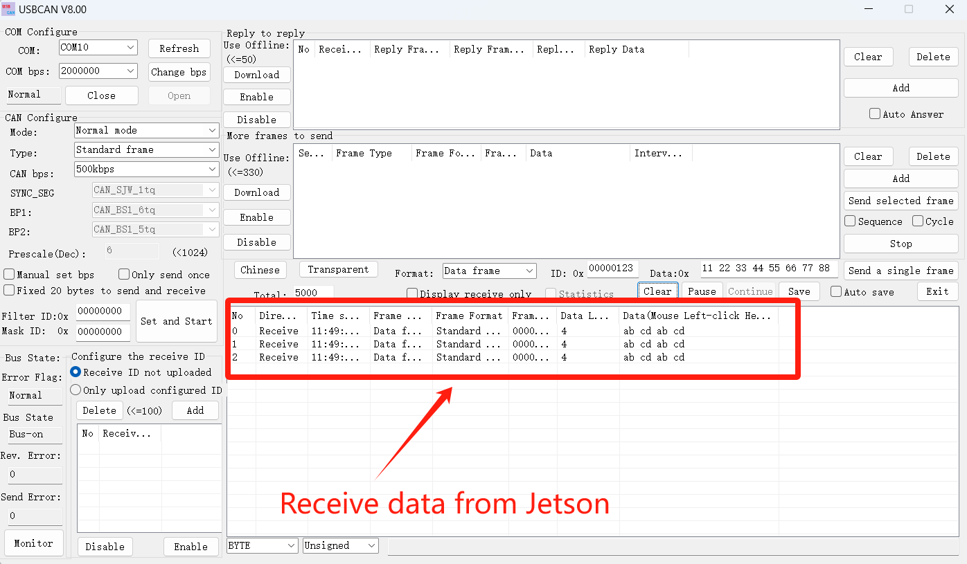
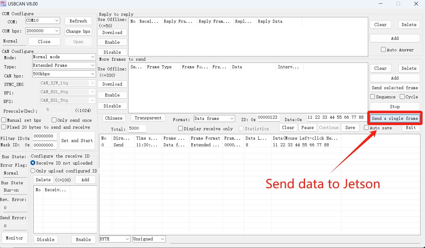
Step 2. Configure the PC data receiving software. Please configure the communication settings as shown in the following picture.
Step 3. Jetson sends data to the PC:
cansend can1 123#abcdabcd
Step 3. PC sends data to the Jetson:
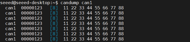
#CAN1 monitors PC data
candump can1
It can be seen that the Jetson terminal has received the data sent by the PC.
CAN FD Mode
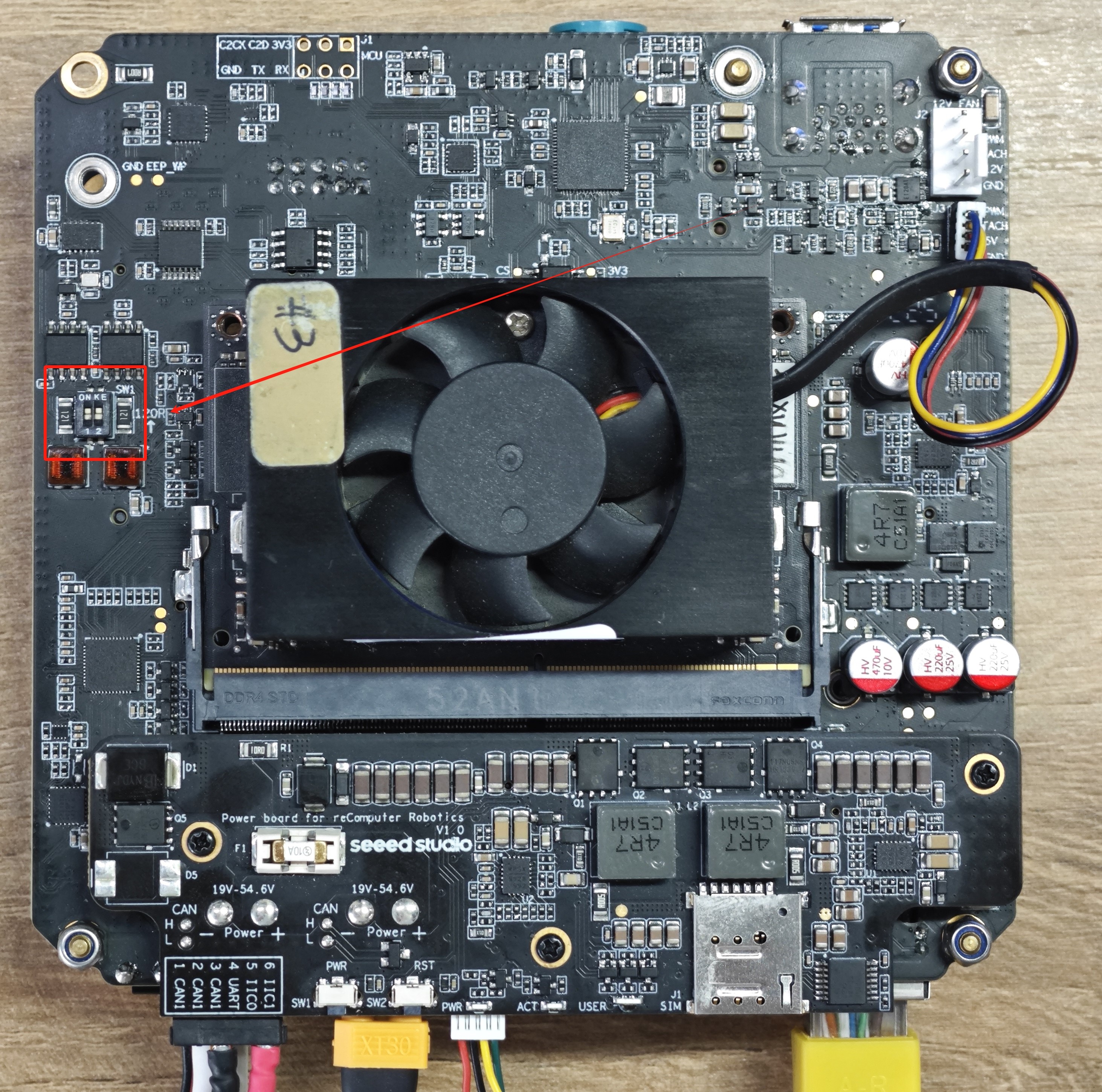
Here, I use CAN0 to connect to CAN1 to demonstrate how multiple Jetson devices can communicate via the CAN interface.
Hardware Connection
Step 1. Remove the bottom cover and set both 120Ω termination resistors to the ON position.
Step 2. Configure CAN0 and CAN1 interfaces:
#close the interface

sudo ip link set can0 down
sudo ip link set can1 down

#Set to FD mode

sudo ip link set can0 type can bitrate 500000 dbitrate 2000000 fd on
sudo ip link set can1 type can bitrate 500000 dbitrate 2000000 fd on

#open the interface
sudo ip link set can0 up
sudo ip link set can1 up
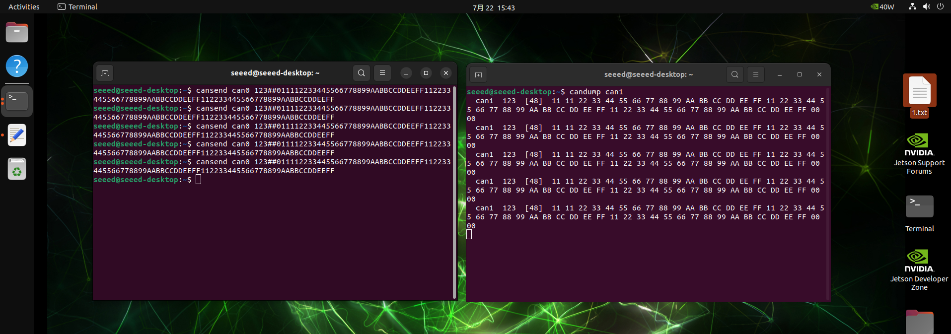
Step 3. Open a new terminal to listen to CAN1 and via CAN0 send data to CAN1:
#open a new terminal and run
candump can1

#another terminal sends data
cansend can0 123##011112233445566778899AABBCCDDEEFF112233445566778899AABBCCDDEEFF112233445566778899AABBCCDDEEFF
123is ID##Indicates CAN FD frame- The following is 64 bytes of data (a total of 128 hexadecimal characters)
UART
The Robotics J401 provides a standard 4-pin JST header for UART serial communication.
Hardware Connection
For UART communication, please follow the following wiring. Here, we use the USB to TTL tool as an example.

Usage Instruction
Step 1. Open the terminal on the Jetson device and run the following command to enable the UART interface:
gpioset --mode=time --sec=100 2 5=0
Step 2. Connect the USB to TTL tool to the Robotics J401 UART port and the PC.
Step 3. Open the serial port tool on the PC side (Here,we use the xcom tool as an example.) and set the baud rate to 115200.
Step 4. Create a simple Python script for serial communication:
import serial
import time

ser = serial.Serial('/dev/ttyTHS1', 115200, timeout=1)
ser.write(b'Hello Jetson!\n')
while True:

    if ser.in_waiting:
        data = ser.readline()
        print("get:", data.decode('utf-8').strip())
    time.sleep(0.1)

ser.close()
Step 5. Run the Python script on the Jetson device:
python3 uart_test.py
Step 6. Now you can see the output on the PC side, and you can also send data from the PC to the Jetson device:


I2C
Robotics J401 provides two I2C interfaces (IIC0 and IIC1) through standard JST 4-pin headers. Enables easy connection of sensors and peripherals for system expansion.
Hardware Connection
The Robotics J401 features two 4-pin GH-1.25 IIC interfaces, IIC0 and IIC1.
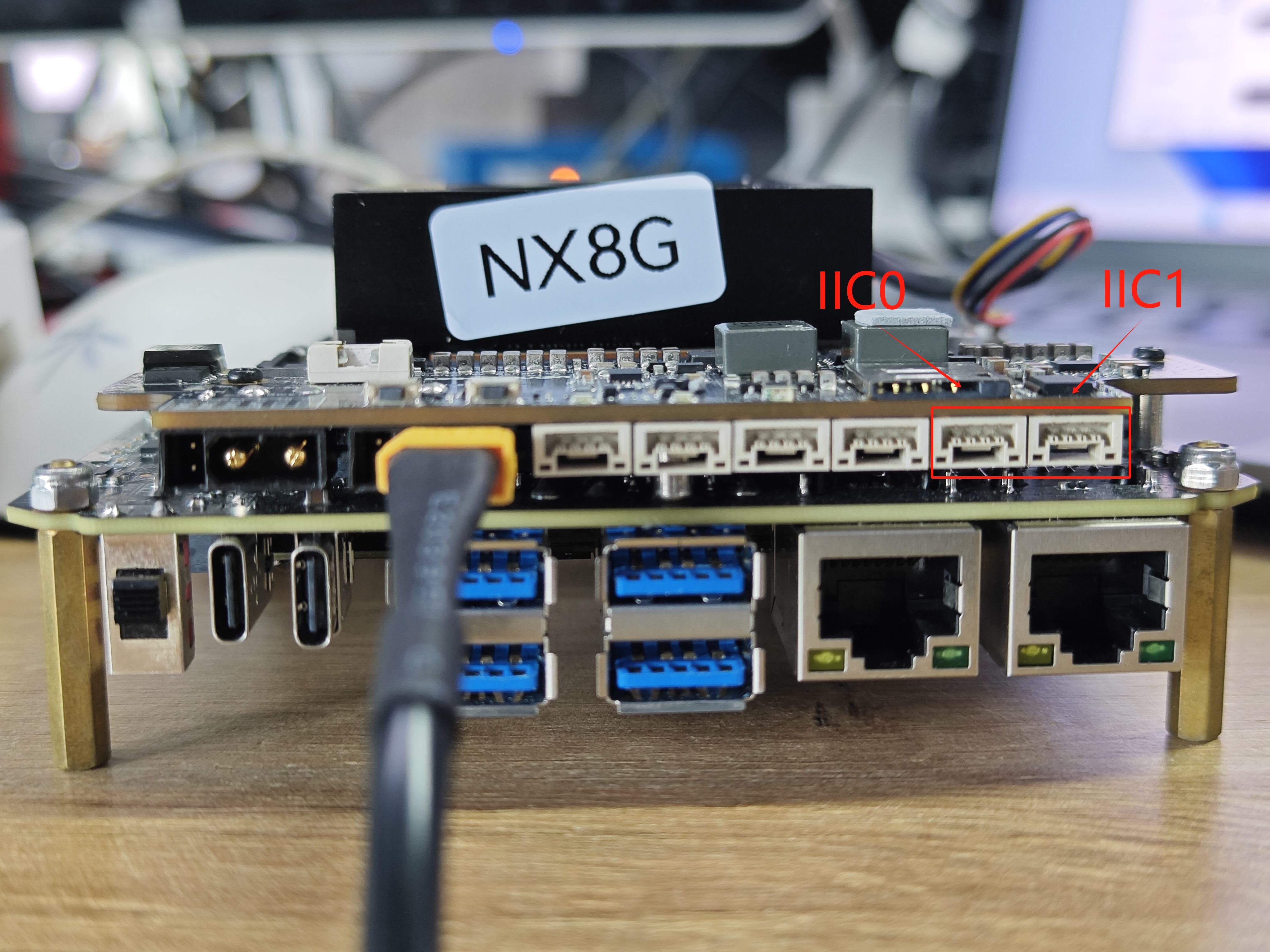
In the datasheet, you can find the wiring diagram for the IIC0/IIC1 4-pin GH-1.25 interface as shown below:

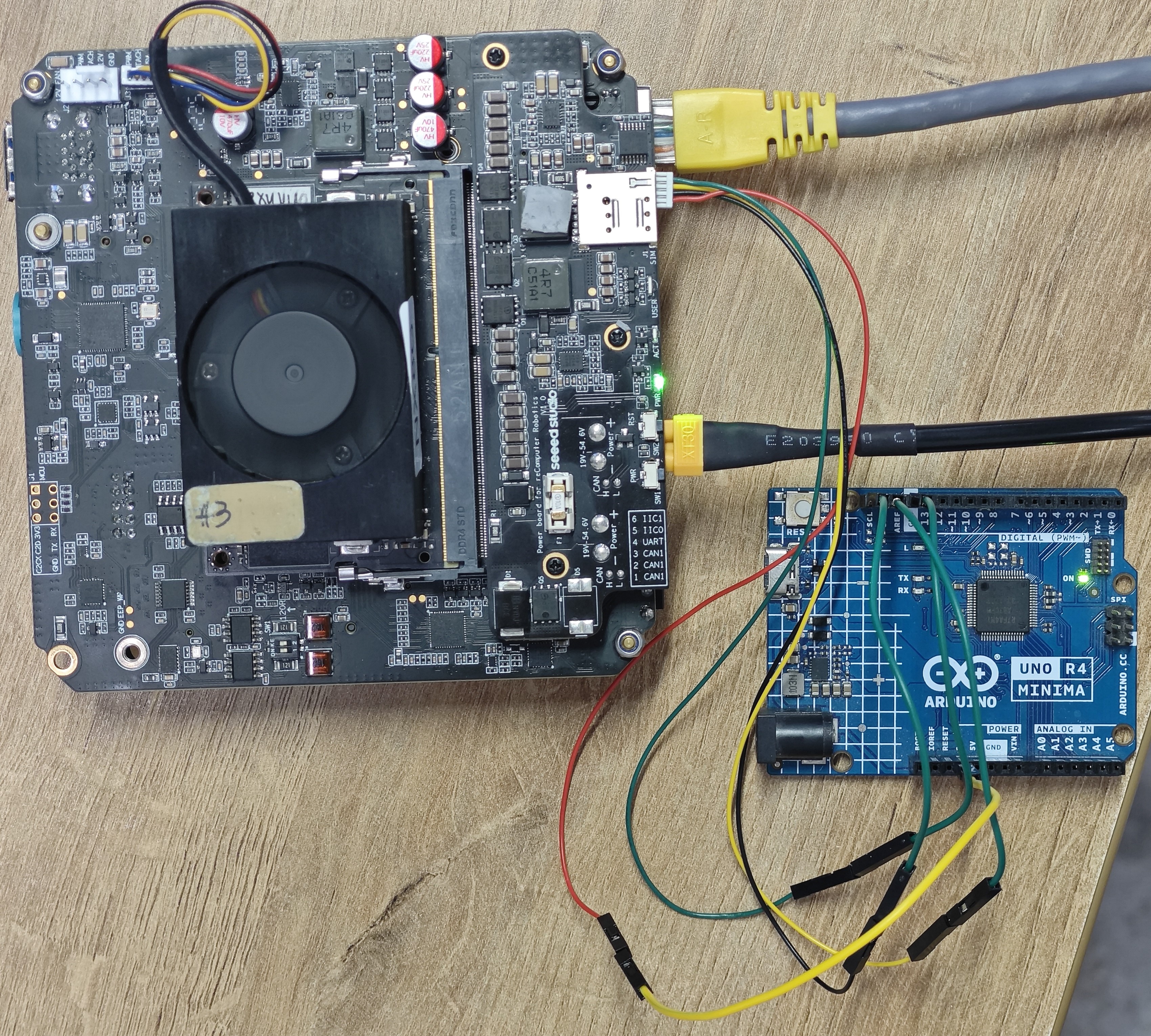
Select an IIC interface device for testing; the choice is up to you. Here, we use a Arduino-Uno-Rev4-Minima to test I2C0/I2C1.
The testing process here involves scanning for the addresses of externally connected devices on IIC0/IIC1.
Please connect the devices(IIC0/IIC1 ↔ Device) according to the following connections:
-
Power → Power
-
SDA → SDA
-
SCL → SCL
-
Ground → Ground
Usage Instruction
Step 1. Download the Arduino IDE to upload he code.
Step 2. Select the type of the development board.
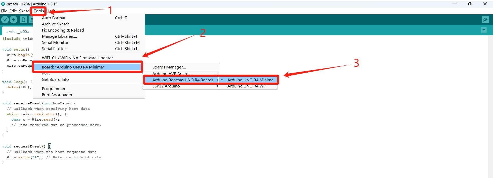
Step 3. Restart the IDE and upload you code.
#code example
#include <Wire.h>

void setup() {
  Wire.begin(0x08); // Set the I2C slave address to 0x08
  Wire.onReceive(receiveEvent);
  Wire.onRequest(requestEvent);
}

void loop() {
  delay(100);
}

void receiveEvent(int howMany) {
  // Callback when receiving host data
  while (Wire.available()) {
    char c = Wire.read();
    // Data received can be processed here.
  }
}

void requestEvent() {
  // Callback when the host requests data
  Wire.write("A"); // Return a byte of data
}
Step 4. Jetson install the tools for IIC testing.
sudo apt update
sudo apt-get install i2c-tools
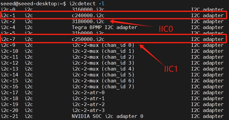
Step 5. Run the following command in the terminal to view the mapped names on the IIC bus:
i2cdetect -l
Step 6. Run the following commands to scan on IIC0:
sudo i2cdetect -y -r 1
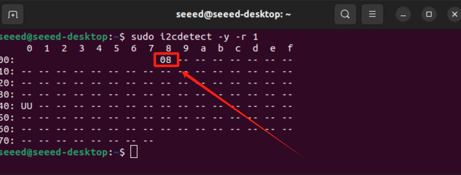
We can see that the device connected to IIC0 is set to address 0x08.
Extension Port
The Robotics j401 carrier board features a Camera Expansion Header for GMSL extension board.It can simultaneously connect and operate four GMSL cameras at the same time.
Hardware Connection
Here are the Robotics j401 carrier board GMSL camera expansion board connection slot(need to prepare an extension board in advance):

The following are the GMSL camera models that we have already supported:
- SG3S-ISX031C-GMSL2F
- SG2-AR0233C-5200-G2A
- SG2-IMX390C-5200-G2A
- SG8S-AR0820C-5300-G2A
- Orbbec Gemini 335Lg
Usage Instruction
Before enabling the GMSL functionality, please ensure that you have installed a JetPack version with the GMSL expansion board driver.
Configure the Jetson IO file
sudo /opt/nvidia/jetson-io/jetson-io.py
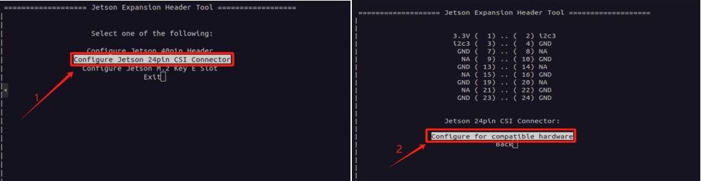
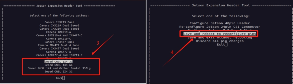
There are three overlay files in total, namely Seeed GMSL 1X4 3G, Seeed GMSL 1X4 6G, Seeed GMSL 1X4, and Orbbec Gemini 335Lg. These correspond to the 3G camera of SG3S, the 6G camera of SG2 and SG8S, and the camera of Orbbec respectively. As shown in Figure 3, please configure the io file according to the model of your camera.
step 2. Install the video interface configuration tools.
sudo apt update
sudo apt install v4l-utils
Use the camera of Gemini 335Lg
#Download the Orbbec Gemini 335Lg visualization tool
wget https://github.com/orbbec/OrbbecSDK_v2/releases/download/v2.4.8/OrbbecViewer_v2.4.8_202507031357_a1355db_linux_aarch64.zip
#unzip and run the UI tool
unzip OrbbecViewer_v2.4.8_202507031357_a1355db_linux_aarch64.zip
cd OrbbecViewer_v2.4.8_202507031357_a1355db_linux_aarch64
./OrbbecViewer
The first time you turn it on, you might need to update the firmware.
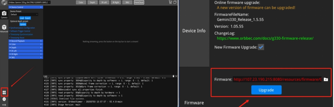
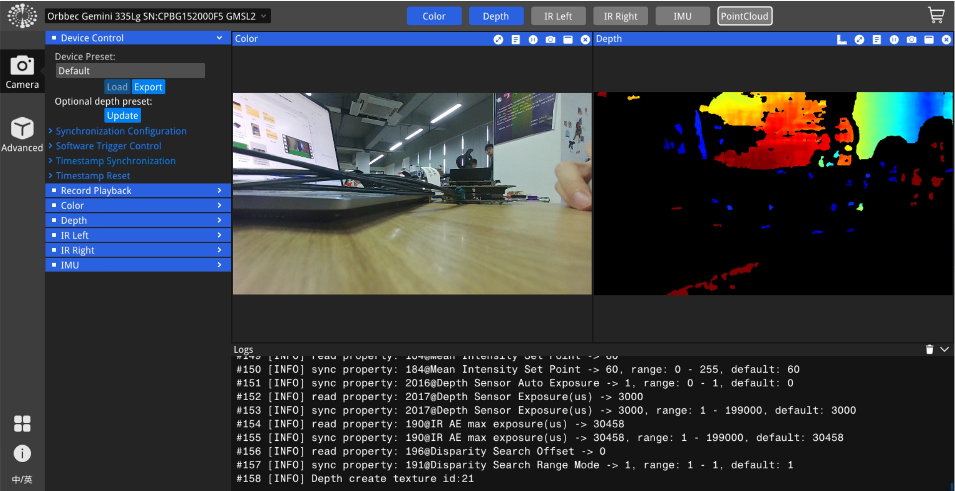
Opening the data stream, you can view the video from the camera.
Use the cameras of SGxxx Series
step 1. Set frame synchronization mode(It is not enabled by default!).
Here we demonstrate how to configure cameras of different models and resolutions.
#enables frame synchronization
v4l2-ctl -d /dev/video0 --set-ctrl=trig_mode=1
#Set the frame rate of the camera
v4l2-ctl -V --set-fmt-video=width=1920,height=1536 -c sensor_mode=0 --stream-mmap -d /dev/video0
#Set the camera format
v4l2-ctl -V --set-fmt-video=width=1920,height=1536 -c sensor_mode=0 -d /dev/video0
trig_mode = 1 enables frame synchronization, while trig_mode = 0 disables frame synchronization. The default setting is to disable frame synchronization.
--set-fmt-video follows the resolution which is selected based on the camera being connected. Currently, there are three sensor_mode options, each corresponding to a different resolution.
- sensor_mode=0 -------> YUYV8_1X16/1920x1536
- sensor_mode=1 -------> YUYV8_1X16/1920x1080
- sensor_mode=2 -------> YUYV8_1X16/3840x2160
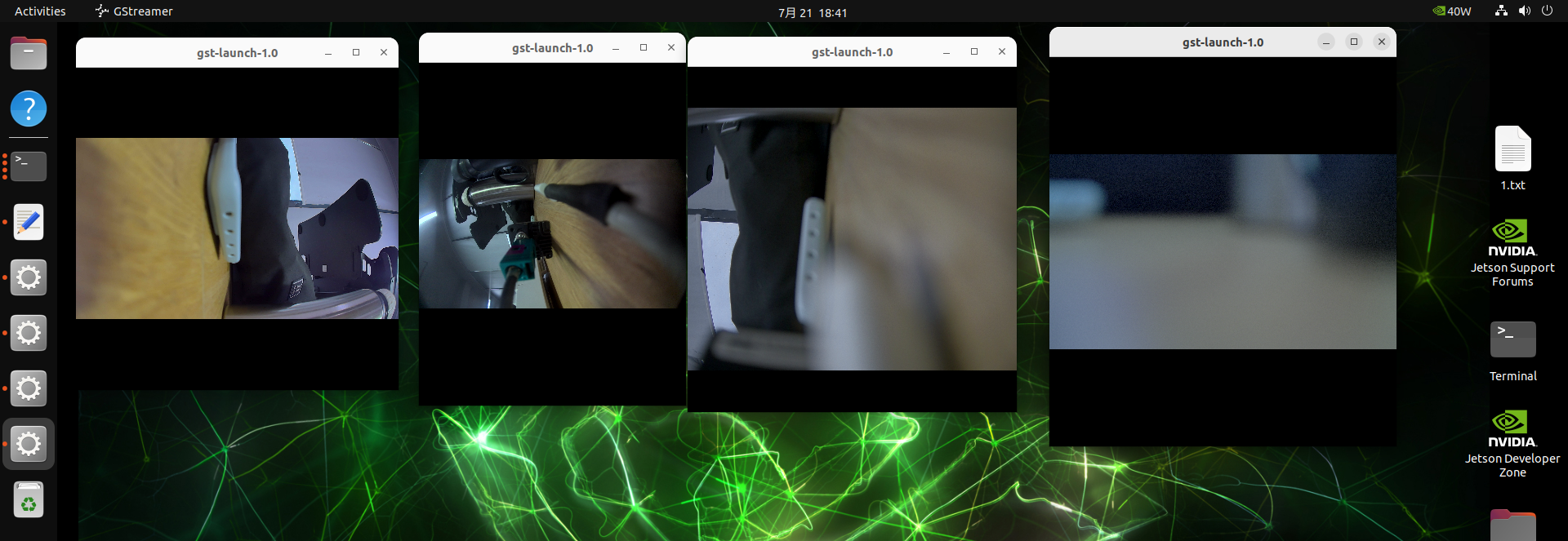
step 2. Start the camera.
gst-launch-1.0 \
    v4l2src device=/dev/video0 ! \
    video/x-raw,format=YUY2,width=1920,height=1080,framerate=30/1 ! \
    videoconvert ! \
    videoscale ! \
    xvimagesink

gst-launch-1.0 \
    v4l2src device=/dev/video1 ! \
    video/x-raw,format=YUY2,width=1920,height=1080,framerate=30/1 ! \
    videoconvert ! \
    videoscale ! \
    xvimagesink

gst-launch-1.0 \
    v4l2src device=/dev/video2 ! \
    video/x-raw,format=YUY2,width=1536,height=1080,framerate=30/1 ! \
    videoconvert ! \
    videoscale ! \
    xvimagesink

gst-launch-1.0 \
    v4l2src device=/dev/video3 ! \
    video/x-raw,format=YUY2,width=3840,height=2160,framerate=30/1 ! \
    videoconvert ! \
    videoscale ! \
    xvimagesink
Display
The reComputer Jetson Robotics J401 is equipped with an DP1.4 (included in Type-C Host) for high-resolution display output.
Resources
- reComputer Robotics J401 Carrier Board Schematic
- reComputer Robotics J401 Carrier Board Datasheet
- reComputer Robotics 3D file
- Mechanical Document-reComputer Robotics PCBA
- Seeed NVIDIA Jetson Product Catalog
- Nvidia Jetson Comparison
- Seeed Nvidia Jetson Success Cases
- Seeed Jetson One Pager
Tech Support & Product Discussion
Thank you for choosing our products! We are here to provide you with different support to ensure that your experience with our products is as smooth as possible. We offer several communication channels to cater to different preferences and needs.