Robotics J601 carrier board Hardware Interfaces Usage
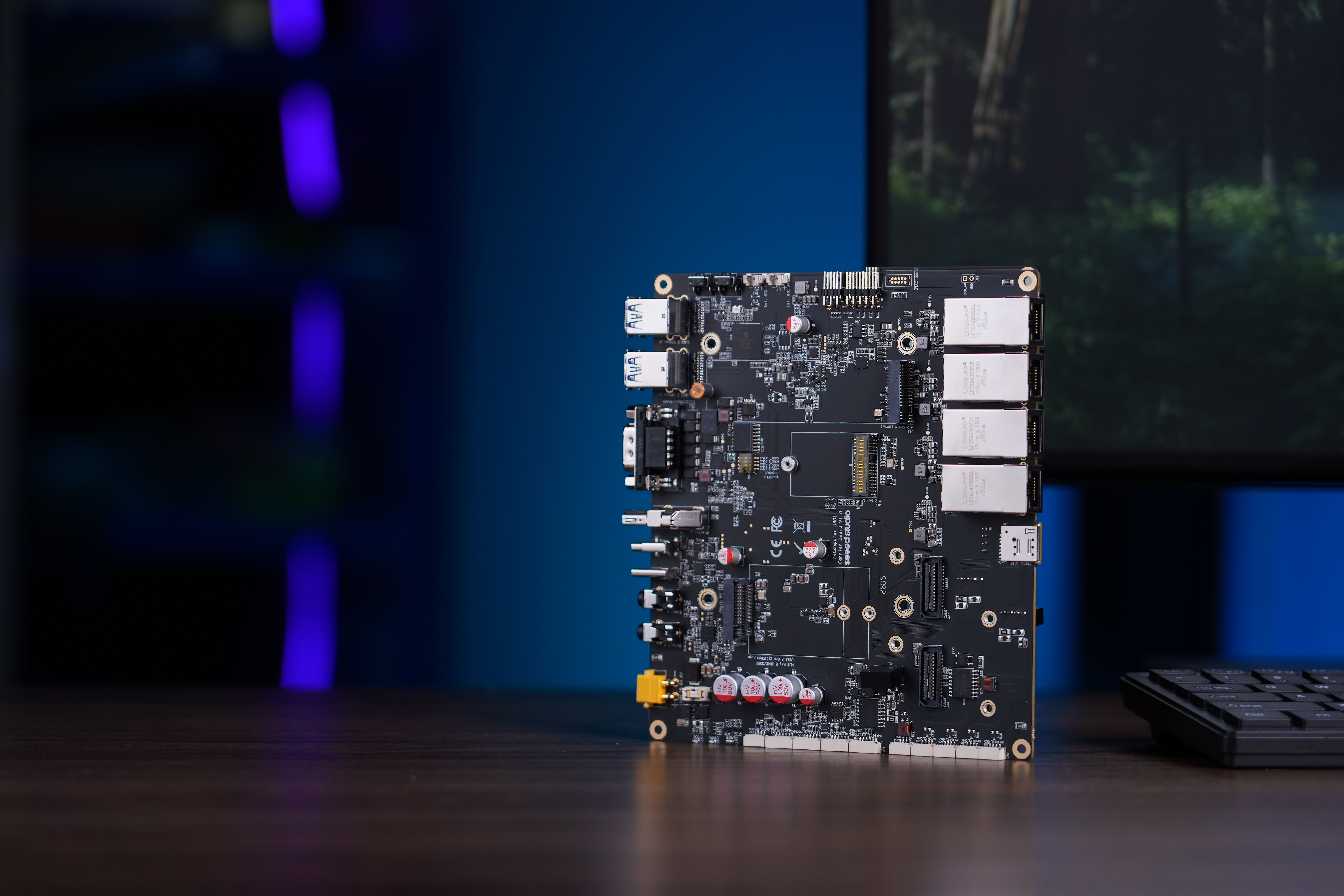
The reComputer Robotics J601 is a high-performance robotics carrier board designed for the NVIDIA Jetson AGX Thor module, targeting advanced embodied AI and robotic control applications. Equipped with extensive connectivity options — including 4x 10GbE Ethernet, M.2 slots for 5G and Wi-Fi/BT modules, USB 3.2 ports, 4x CAN (with CAN FD support), RS-232/422/485, I2C, I2S, UART, GPIO (GPI/GPO), GMSL2 expansion (up to 8 cameras), and wide-range DC input — it serves as a powerful robotic brain capable of processing complex data from various sensors.
Supporting frameworks like NVIDIA Isaac ROS, Hugging Face, PyTorch, and ROS 2/1, the reComputer Robotics J601 bridges large language model-driven decision-making with physical robotics control, such as motion planning and sensor fusion. Ideal for the rapid development of autonomous robots, it accelerates time-to-market with ready-to-use interfaces and optimized AI frameworks.
USB
The Robotics J601 carrier board is equipped with multiple USB ports, including 4x USB 3.2 Type-A ports (Host, 10Gbps) for high-speed peripheral connectivity, one USB 3.2 Type-C port (J4) for recovery/flashing, and one USB 2.0 Type-C port (J3) for device mode/debugging.
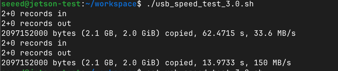
USB 3.2 Speed Test
Plug in a USB 3.0 flash drive and test its read/write speed. Note that actual speeds depend on the USB drive's own performance.
Create a test script:
vim test_usb_speed.sh
Paste the following content:
#!/bin/bash

echo "seeed" | sudo -S dd if=/dev/zero of=/dev/sda bs=1000M count=2 conv=fdatasync
sleep 1
sudo sh -c "sync && echo 3 > /proc/sys/vm/drop_caches"
sleep 1
echo "seeed" | sudo -S dd if=/dev/sda of=/dev/null bs=1000M count=2
Replace /dev/sda with the actual device name of your USB drive. You can use lsblk to check.
Make the script executable and run it:
chmod +x test_usb_speed.sh
./test_usb_speed.sh
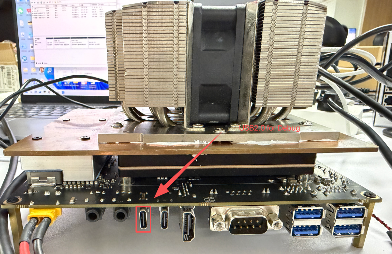
USB 2.0 Type-C Debug Port
Using this serial port, via the USB-C data cable, you can monitor the debugging information of input and output on the PC side.
Windows
Step 1. Connect the J601 to the PC via a USB-C data cable.
Step2. Download the CP210X Driver on your PC.

Step3. Connect the PC via a USB data cable, extract the downloaded file and install driver on your PC.

Step4. Open the Device Manager on your Windows PC and check the COM port number assigned to the reComputer J601. It should appear under "Ports (COM & LPT)" as "Silicon Labs CP210x USB to UART Bridge (COMX)", where X is the COM port number.

Step5. Open the serial port tool(Here, we use the MobaXterm tool as an example), create a new session.

Step6. Select the Serial tool.

Step7. Select corresponding serial port, set the baud rate to 115200 and click "OK".

Step8. Login your reComputer J601 with the username and password.

Linux
Step 1. Connect the J601 to the Linux PC via a USB-C data cable.
Step 2. Find the serial device:
ls /dev/ttyUSB*

Step 3. Connect to the serial console:
screen /dev/ttyUSB0 -b 115200
You should now see the J601 serial console output and can log in with your username and password.
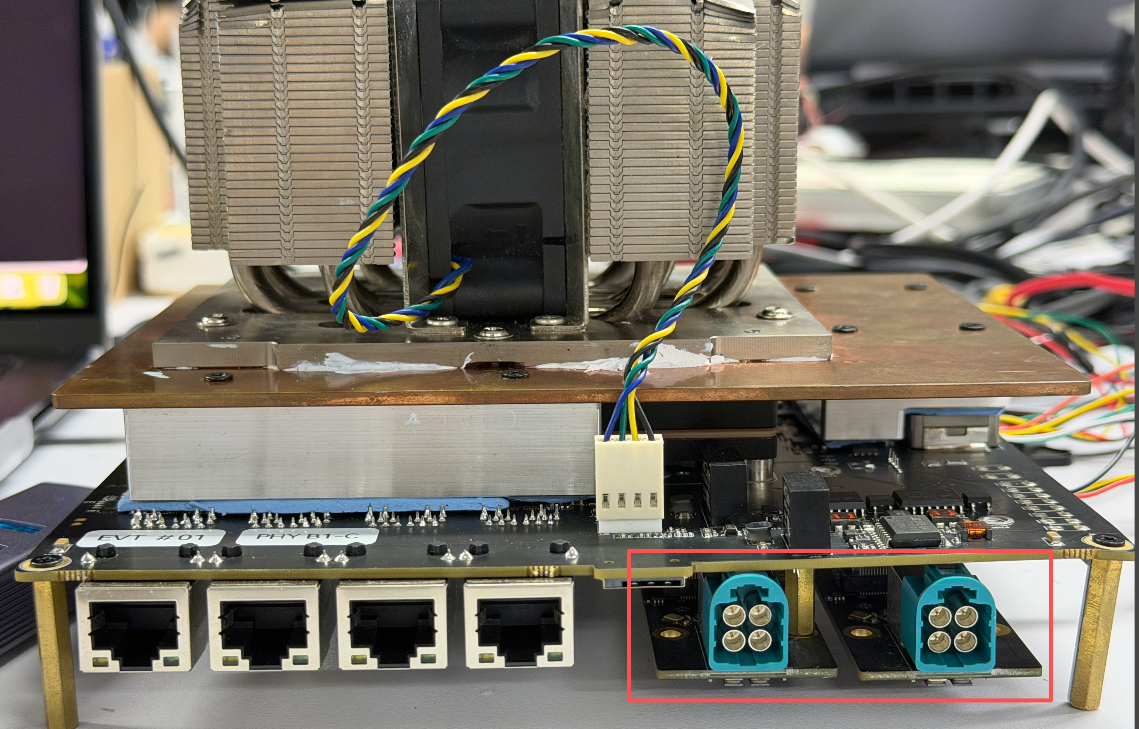
GMSL
The Robotics J601 features a GMSL camera expansion header that supports up to 8 GMSL cameras simultaneously, enabling multi-camera robotic vision applications.
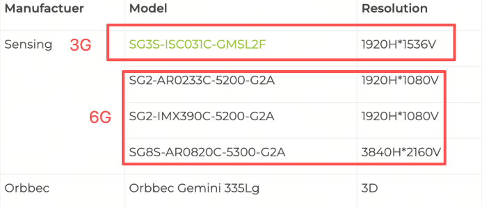
Supported GMSL Camera Models
- SG3S-ISX031C-GMSL2F
- SG2-AR0233C-5200-G2A
- SG2-IMX390C-5200-G2A
- SG8S-AR0820C-5300-G2A
- Orbbec Gemini 335Lg
Hardware Connection
Connect the GMSL expansion board to the camera expansion header on the J601 carrier board, then connect your GMSL cameras to the expansion board.
Usage Instruction
Before enabling the GMSL functionality, please ensure that you have installed a JetPack version with the GMSL expansion board driver.
Step 1. Install the video interface configuration tools:
sudo apt update
sudo apt install v4l-utils wmctrl
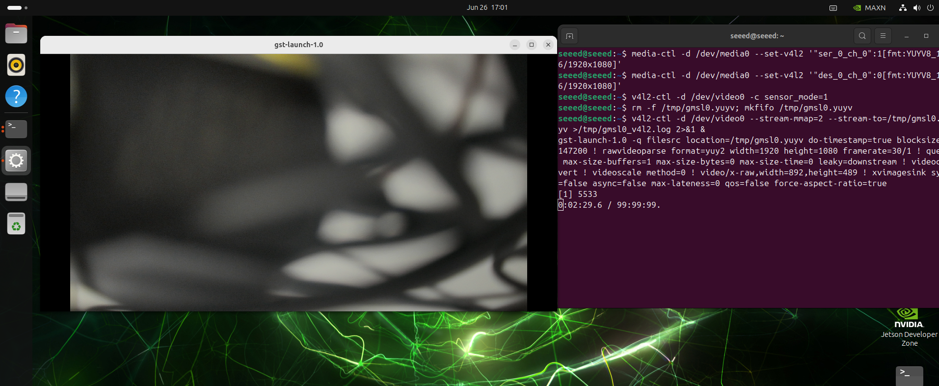
#example
media-ctl -d /dev/media0 --set-v4l2 '"ser_0_ch_0":1[fmt:YUYV8_1X16/1920x1080]'
media-ctl -d /dev/media0 --set-v4l2 '"des_0_ch_0":0[fmt:YUYV8_1X16/1920x1080]'
v4l2-ctl -d /dev/video0 -c sensor_mode=1
rm -f /tmp/gmsl0.yuyv; mkfifo /tmp/gmsl0.yuyv
v4l2-ctl -d /dev/video0 --stream-mmap=2 --stream-to=/tmp/gmsl0.yuyv >/tmp/gmsl0_v4l2.log 2>&1 &
gst-launch-1.0 -q filesrc location=/tmp/gmsl0.yuyv do-timestamp=true blocksize=4147200 ! rawvideoparse format=yuy2 width=1920 height=1080 framerate=30/1 ! queue max-size-buffers=1 max-size-bytes=0 max-size-time=0 leaky=downstream ! videoconvert ! videoscale method=0 ! video/x-raw,width=892,height=489 ! xvimagesink sync=false async=false max-lateness=0 qos=false force-aspect-ratio=true
Use the Camera of Gemini 335Lg
# Download the Orbbec Gemini 335Lg visualization tool
wget https://github.com/orbbec/OrbbecSDK_v2/releases/download/v2.4.8/OrbbecViewer_v2.4.8_202507031357_a1355db_linux_aarch64.zip
# Unzip and run the UI tool
unzip OrbbecViewer_v2.4.8_202507031357_a1355db_linux_aarch64.zip
cd OrbbecViewer_v2.4.8_202507031357_a1355db_linux_aarch64
./OrbbecViewer
The first time you turn it on, you might need to update the firmware. Opening the data stream, you can view the video from the camera.
UART
The Robotics J601 provides a UART interface via a standard JST header for serial communication with external devices. The UART port is connected to /dev/ttyTHS1 on the Jetson system with a default baud rate of 115200.
Hardware Connection
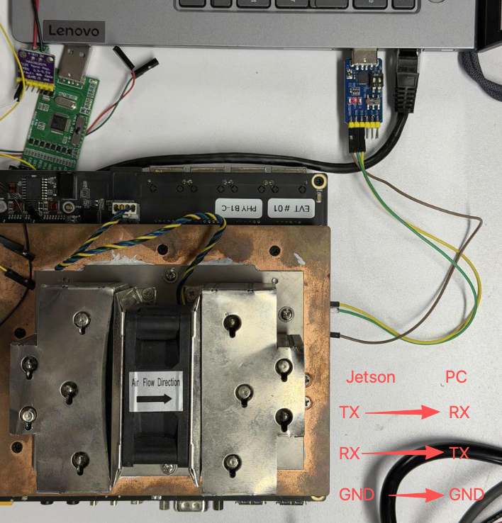
For UART communication, connect the USB-to-TTL tool according to the following wiring:
- TX → RX
- RX → TX
- GND → GND
Usage Instruction
Connect the USB-to-TTL tool to the Robotics J601 UART port and the PC, then open the serial port tool on the PC side and set the baud rate to 115200.
You can use a simple Python script for serial communication testing:
import serial
import time

ser = serial.Serial('/dev/ttyTHS1', 115200, timeout=1)
ser.write(b'Hello Jetson!\n')
while True:
    if ser.in_waiting:
        data = ser.readline()
        print("get:", data.decode('utf-8').strip())
    time.sleep(0.1)

ser.close()
Run the script on the Jetson device:
python3 uart_test.py
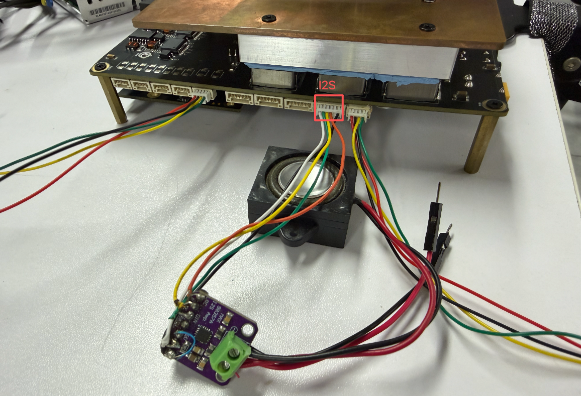
I2S
The Robotics J601 provides an I2S audio interface with amplifier output and microphone input for audio playback and recording. The I2S interface is exposed via the J14 JST GH-1.25 connector.
Pin Definition
| Pin # | Module Pin Name | Module Pin # | Usage/Description | Type/Dir |
|---|---|---|---|---|
| 1 | - | - | 3V3 Power Supply | Power |
| 2 | I2S2_DIN | F6 | I2S2 Audio Port 2 Data In (Level Shifted from 1.8V to 3.3V) | Input |
| 3 | I2S2_FS | E4 | I2S2 Audio Port 2 Left/Right Clock (Level Shifted from 1.8V to 3.3V) | Bidir |
| 4 | I2S2_CLK | G4 | I2S2 Audio Port 2 Clock (Level Shifted from 1.8V to 3.3V) | Bidir |
| 5 | I2S2_DOUT | F5 | I2S2 Audio Port 2 Data Out (Level Shifted from 1.8V to 3.3V) | Output |
| 6 | - | - | Ground | Ground |
Hardware Connection
Usage Instruction
Step 1. Configure the I2S2 audio mux and test tone output:
# Configure I2S2 mux
amixer -c 2 sset "I2S2 Mux" "ADMAIF1"

# Play a 440Hz sine wave test tone (one iteration)
speaker-test -D hw:2,0 -c 2 -r 48000 -t sine -f 440 -l 1
The -l 1 flag means the test tone will play only once and then stop.
Step 2. Play your own audio file:
aplay -D hw:2,0 -c 2 -r 48000 your_audio_file.wav
Replace your_audio_file.wav with the path to your actual audio file. Ensure the audio file format matches the specified sample rate (48000 Hz) and channel count (2).
I2C
The Robotics J601 provides an I2C interface via the J12 JST GH-1.25 connector, enabling easy connection of sensors and peripherals for system expansion.
Pin Definition
| Pin # | Module Pin Name | Module Pin # | Usage/Description | Type/Dir |
|---|---|---|---|---|
| 1 | - | - | Ground | Ground |
| 2 | DP_AUX_CH2_N | E18 | I2C4_SDA_3V3 | Bidir |
| 3 | DP_AUX_CH2_P | E19 | I2C4_SCL_3V3 | Output |
| 4 | - | - | 3V3 Power Supply | Power |
The I2C connector uses the I2C4 bus on the Jetson AGX Thor SoC.
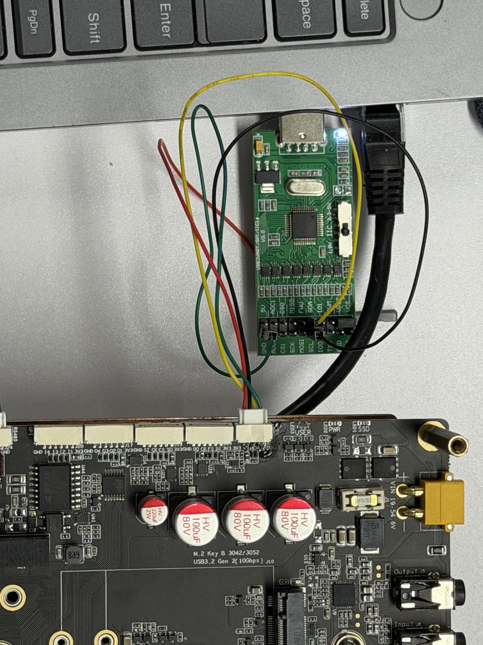
Hardware Connection
Connect your I2C device to the I2C interface on the carrier board:
- Ground → Ground (Pin 1)
- SDA → SDA (Pin 2)
- SCL → SCL (Pin 3)
- Power → 3V3 (Pin 4)
Usage Instruction
Step 1. Install the I2C testing tools:
sudo apt update
sudo apt-get install i2c-tools
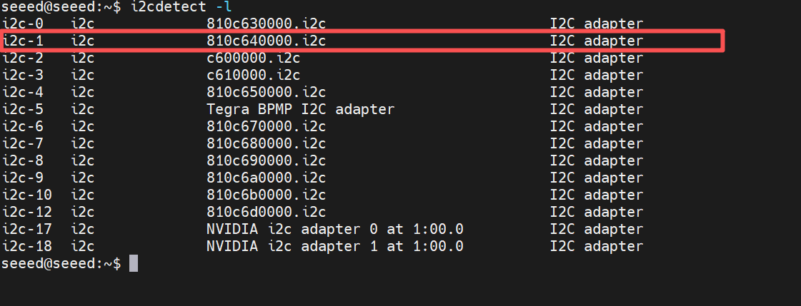
Step 2. View the I2C bus mappings:
i2cdetect -l
Step 3. Scan for devices on the I2C bus:
sudo i2cdetect -y -r 1
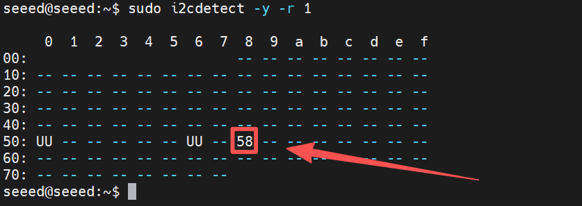
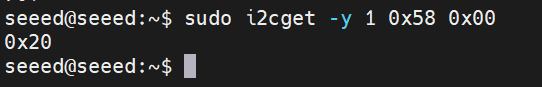
Step 4. Read a register from an I2C device. For example, to read register 0x00 from a device at address 0x58 on bus i2c-1:
sudo i2cget -y 1 0x58 0x00
GPIO (GPI/GPO)
The Robotics J601 provides digital GPIO interfaces via two JST GH-1.25 connectors: a GPI (General Purpose Input) connector J20 with 4 input channels, and a GPO (General Purpose Output) connector J14 with 4 output channels. All GPIO signals are level-shifted from 1.8V (SoC domain) to 3.3V, making them directly compatible with standard 3.3V sensors and peripherals.
Pin Definition
GPI Connector - J20 (Input)
| Pin # | Module Pin Name | Module Pin # | Usage/Description | Type/Dir |
|---|---|---|---|---|
| 1 | - | - | 3V3 Power Supply | Power |
| 2 | SPI2_MISO | D62 | GPI_1_3V3 (Level Shifted from 1.8V to 3.3V) | Input, 3.3V |
| 3 | GPIO64 | J6 | GPI_2_3V3 (Level Shifted from 1.8V to 3.3V) | Input, 3.3V |
| 4 | GPIO65 | J7 | GPI_3_3V3 (Level Shifted from 1.8V to 3.3V) | Input, 3.3V |
| 5 | GPIO49 | G6 | GPI_4_3V3 (Level Shifted from 1.8V to 3.3V) | Input, 3.3V |
| 6 | - | - | Ground | Ground |
GPO Connector - J14 (Output)
| Pin # | Module Pin Name | Module Pin # | Usage/Description | Type/Dir |
|---|---|---|---|---|
| 1 | - | - | 3V3 Power Supply | Power |
| 2 | GPIO13 | G7 | GPO_1_3V3 (Level Shifted from 1.8V to 3.3V) | Output, 3.3V |
| 3 | SPI2_CS0_N | D60 | GPO_2_3V3 (Level Shifted from 1.8V to 3.3V) | Output, 3.3V |
| 4 | SPI2_CLK | E61 | GPO_3_3V3 (Level Shifted from 1.8V to 3.3V) | Output, 3.3V |
| 5 | SPI2_MOSI | F60 | GPO_4_3V3 (Level Shifted from 1.8V to 3.3V) | Output, 3.3V |
| 6 | - | - | Ground | Ground |
Hardware Connection
Connect your GPIO device to the GPI or GPO connector on the carrier board using a GH-1.25 cable:
- VCC → 3V3 (Pin 1)
- Signal → GPI/GPO pin (Pin 2–5)
- GND → Ground (Pin 6)
Usage Instruction
The GPI and GPO pins are accessible via libgpiod (gpioset/gpioget). You can find the GPIO chip and line numbers using gpioinfo.
Step 1. Install the GPIO utilities:
sudo apt update
sudo apt-get install gpiod
Step 2. View all available GPIO chips and lines:
gpioinfo
Step 3. Read a GPI pin. For example, to read GPI_2 (GPIO64, Pin 3 on J20):
# Replace <chip> and <line> with the actual GPIO chip/line numbers from gpioinfo
gpioget <chip> <line>
Step 4. Write a GPO pin. For example, to set GPO_1 (GPIO13, Pin 2 on J14) high:
# Replace <chip> and <line> with the actual GPIO chip/line numbers from gpioinfo
gpioset <chip> <line>=1
Step 5. Use the pins in a Python script with the gpiod library:
import gpiod

# Replace chip and line numbers based on your gpioinfo output
chip = gpiod.Chip('<chip_number>')

# Read GPI example
gpi_line = chip.get_line(<gpi_line_number>)
gpi_line.request(consumer="gpi_test", type=gpiod.LINE_REQ_DIR_IN)
print("GPI value:", gpi_line.get_value())

# Write GPO example
gpo_line = chip.get_line(<gpo_line_number>)
gpo_line.request(consumer="gpo_test", type=gpiod.LINE_REQ_DIR_OUT)
gpo_line.set_value(1)  # Set high
CAN
CAN (Controller Area Network) is a robust vehicle bus standard that enables microcontrollers and devices to communicate with each other without a host computer. The Robotics J601 provides 4 CAN interfaces (CAN0, CAN1, CAN2, CAN3) via JST GH-1.25 connectors, all supporting CAN FD mode.
CAN Connector Pin Mapping
| CAN Interface | Connector | Pin 1 | Pin 2 | Pin 3 | Pin 4 |
|---|---|---|---|---|---|
| CAN0 | J31 | Ground | CAN0_L_ISO | CAN0_H_ISO | 5V Power |
| CAN1 | J30 | Ground | CAN1_L_ISO | CAN1_H_ISO | 5V Power |
| CAN2 | J28 | Ground | CAN2_L_ISO | CAN2_H_ISO | 5V Power |
| CAN3 | J25 | Ground | CAN3_L_ISO | CAN3_H_ISO | 5V Power |
All 4 CAN interfaces are isolated. Each connector provides a 5V power supply on Pin 4.
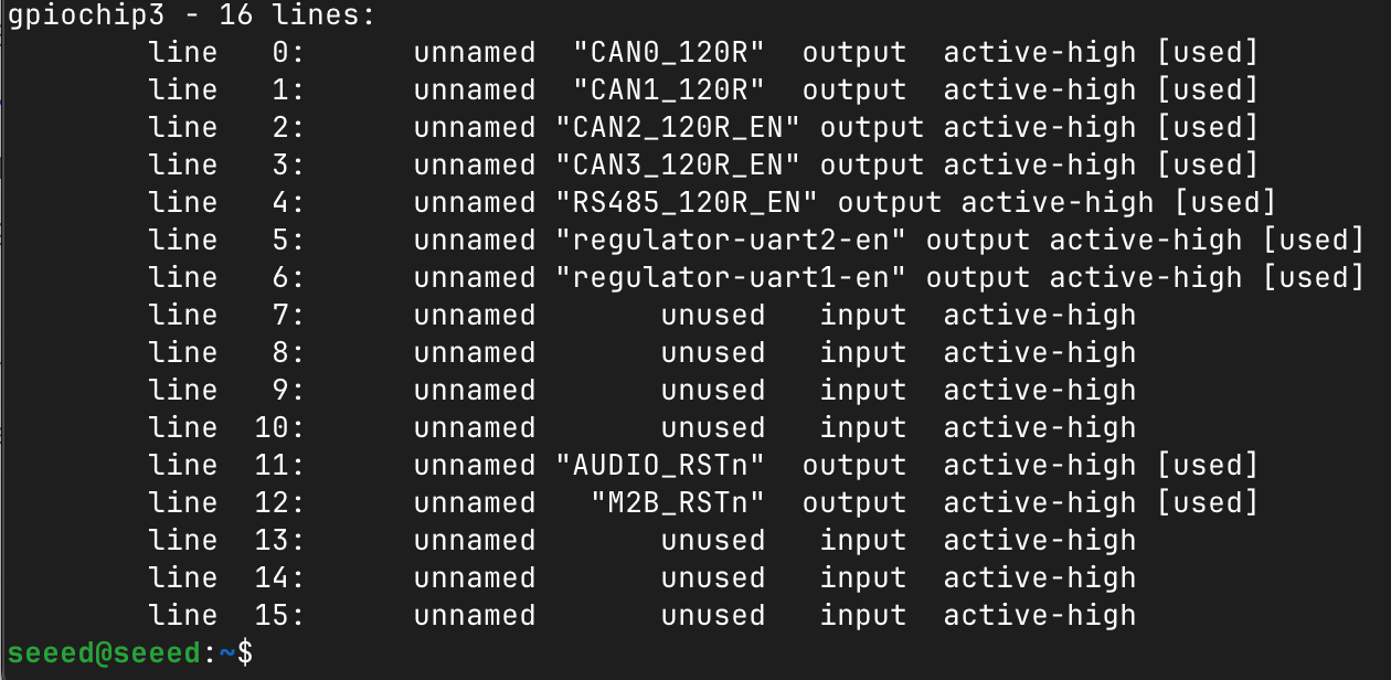
120Ω Termination Resistor Control
Each CAN interface has a software-controlled 120Ω termination resistor. The GPIO mappings are as follows:
| Interface | GPIO Chip | GPIO Line | Control Name |
|---|---|---|---|
| CAN0_120R_EN_3V3 | 3 | 0 | CAN0 termination |
| CAN1_120R_EN_3V3 | 3 | 1 | CAN1 termination |
| CAN2_120R_EN_3V3 | 3 | 2 | CAN2 termination |
| CAN3_120R_EN_3V3 | 3 | 3 | CAN3 termination |
| RS485_120R_EN_3V3 | 3 | 4 | RS485 termination |
You can view the corresponding GPIO lines using:
gpioinfo
CAN Classic Communication
Here we demonstrate data communication between CAN0 and CAN1.
Step 1. Install the CAN utilities:
sudo apt update
sudo apt install can-utils -y
Step 2. Configure the CAN interfaces:
sudo ip link set down can0
sudo ip link set down can1

sudo ip link set can0 type can bitrate 500000
sudo ip link set can1 type can bitrate 500000

sudo ip link set up can0
sudo ip link set up can1
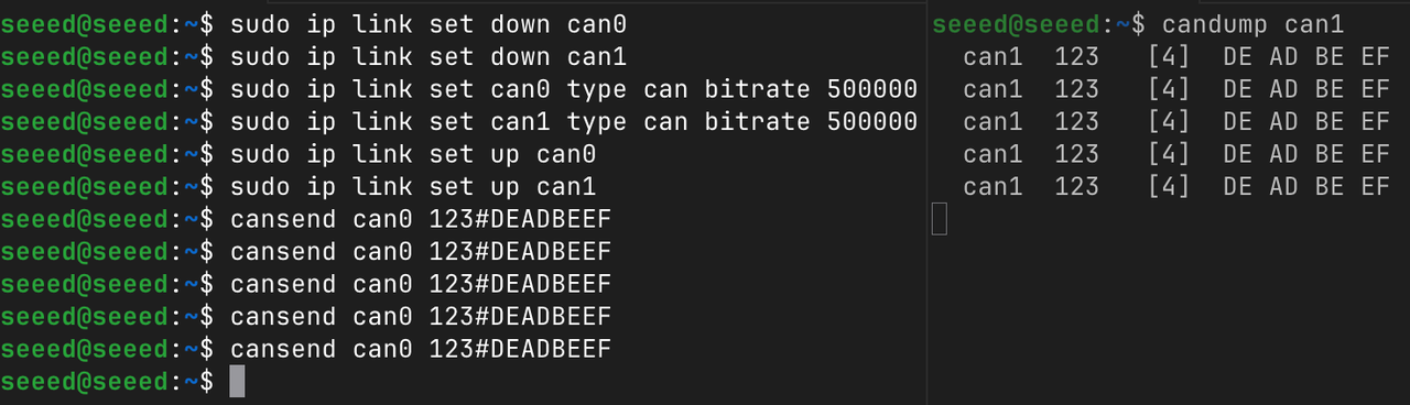
Step 3. Open a new terminal to receive data on CAN1, and send data from CAN0:
# In a new terminal, listen on CAN1
candump can1

# In another terminal, send data from CAN0
cansend can0 123#DEADBEEF
CAN FD Mode
CAN FD (Flexible Data-Rate) extends the classic CAN protocol to support higher data rates and larger payloads (up to 64 bytes).
Step 1. Configure CAN0 and CAN1 for FD mode:
sudo ip link set down can0
sudo ip link set down can1

sudo ip link set can0 type can bitrate 500000 dbitrate 2000000 fd on
sudo ip link set can1 type can bitrate 500000 dbitrate 2000000 fd on

sudo ip link set can0 txqueuelen 2000
sudo ip link set can1 txqueuelen 2000

sudo ip link set up can0
sudo ip link set up can1
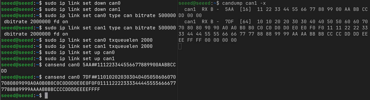
Step 2. Open a new terminal and test CAN FD communication:
# Listen on CAN1 with extended output
candump can1 -x

# Test 1: Send a 16-byte frame with BRS active
cansend can0 5AA##111223344556677889900AABBCCDD

# Test 2: Send a full 64-byte payload frame with BRS active
cansend can0 7DF##1101020203030404050506060707080809090A0A0B0B0C0C0D0D0E0E0F0F0111122223333444455556666777788889999AAAABBBBCCCCDDDDEEEEFFFF
5AA/7DFis the CAN ID##indicates a CAN FD frame- The digit after
##is the BRS (Bit Rate Switch) flag:1= BRS active - The following is the data payload (up to 128 hexadecimal characters for 64 bytes)
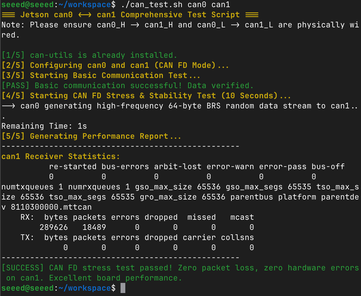
CAN Comprehensive Test Script
The following script performs a complete CAN FD test including dependency check, interface configuration, basic communication verification, and a 10-second stress test.
Create the test script:
vim can_test.sh
Paste the following content:
Click to expand CAN test script
#!/bin/bash

# Color output definitions
GREEN='\033[0;32m'
RED='\033[0;31m'
YELLOW='\033[1;33m'
NC='\033[0m' # No Color

# Assign interfaces from arguments, default to can0 and can1 if empty
TX_DEV=${1:-can0}
RX_DEV=${2:-can1}

echo -e "${YELLOW}=== Jetson $TX_DEV <-> $RX_DEV Comprehensive Test Script ===${NC}"
echo -e "Note: Please ensure ${TX_DEV}_H -> ${RX_DEV}_H and ${TX_DEV}_L -> ${RX_DEV}_L are physically wired.\n"

# 1. Dependency Check
if ! command -v candump &> /dev/null; then
    echo -e "${YELLOW}[1/5] Installing can-utils...${NC}"
    sudo apt update && sudo apt install can-utils -y
else
    echo -e "${GREEN}[1/5] can-utils is already installed.${NC}"
fi

# 2. Reset and Configure Interfaces (Arbitration: 500K, Data: 2M, FD & BRS enabled)
echo -e "${YELLOW}[2/5] Configuring $TX_DEV and $RX_DEV (CAN FD Mode)...${NC}"
for dev in "$TX_DEV" "$RX_DEV"; do
    # Check if the interface exists in the system
    if ! ip link show "$dev" &> /dev/null; then
        echo -e "${RED}[ERROR] Interface $dev does not exist. Please check your spelling or hardware.${NC}"
        exit 1
    fi
    sudo ip link set down "$dev" 2>/dev/null
    sudo ip link set "$dev" type can bitrate 500000 dbitrate 2000000 fd on
    # Increase transmit queue length to prevent packet loss under heavy load
    sudo ip link set "$dev" txqueuelen 2000
    sudo ip link set up "$dev"
done
sleep 1

# 3. Basic Communication Test (Classic CAN Frame)
echo -e "${YELLOW}[3/5] Starting Basic Communication Test...${NC}"
# Listen for 1 frame on the receiver interface in the background and dump to a temp file
candump "$RX_DEV" -n 1 > /tmp/can_test_rx.log &
DUMP_PID=$!
sleep 0.5

# Send a single classic CAN frame from the transmitter interface
cansend "$TX_DEV" 123#DEADBEEF

# Wait for the background dump process to finish
wait $DUMP_PID 2>/dev/null

# Validate basic data
if grep -q "DE AD BE EF" /tmp/can_test_rx.log; then
    echo -e "${GREEN}[PASS] Basic communication successful! Data verified.${NC}"
else
    echo -e "${RED}[FAIL] Basic communication failed! No data received or data corrupted.${NC}"
    tail -n 2 /tmp/can_test_rx.log 2>/dev/null
    exit 1
fi

# 4. CAN FD High-Load Stress Test
echo -e "${YELLOW}[4/5] Starting CAN FD Stress & Stability Test (10 Seconds)...${NC}"
echo -e "--> $TX_DEV generating high-frequency 64-byte BRS random data stream to $RX_DEV..."

# Flood the bus using cangen (-f for FD, -b for BRS, -g 1 for 1ms interval)
cangen "$TX_DEV" -f -b -g 1 >/dev/null 2>&1 &
GEN_PID=$!

# Countdown timer
for i in {10..1}; do
    echo -ne "Remaining Time: ${i}s \r"
    sleep 1
done
echo ""

# Stop data generation
kill $GEN_PID 2>/dev/null
wait $GEN_PID 2>/dev/null
sleep 1

# 5. Analyze and Print Performance Report
echo -e "${YELLOW}[5/5] Generating Performance Report...${NC}"
echo "--------------------------------------------------"
echo -e "${YELLOW}$RX_DEV Receiver Statistics:${NC}"
# Extract packets and hardware error counters
ip -details -statistics link show "$RX_DEV" | grep -E -A 3 "(RX:|errors)"
echo "--------------------------------------------------"

# Smart assessment based on RX errors
ERRORS=$(ip -details -statistics link show "$RX_DEV" | grep -A 1 "RX: errors" | tail -n 1 | awk '{print $1}')
if [ "$ERRORS" ] && [ "$ERRORS" -gt 0 ]; then
    echo -e "${RED}[WARNING] Test completed, but $RX_DEV encountered $ERRORS errors/dropped packets during stress testing. Check your wiring and termination resistors!${NC}"
else
    echo -e "${GREEN}[SUCCESS] CAN FD stress test passed! Zero packet loss, zero hardware errors on $RX_DEV. Excellent board performance.${NC}"
fi

# Cleanup and tear down interfaces
for dev in "$TX_DEV" "$RX_DEV"; do sudo ip link set down "$dev"; done
rm -f /tmp/can_test_rx.log
Make the script executable and run it to test any two CAN interfaces:
chmod +x can_test.sh
./can_test.sh can0 can1
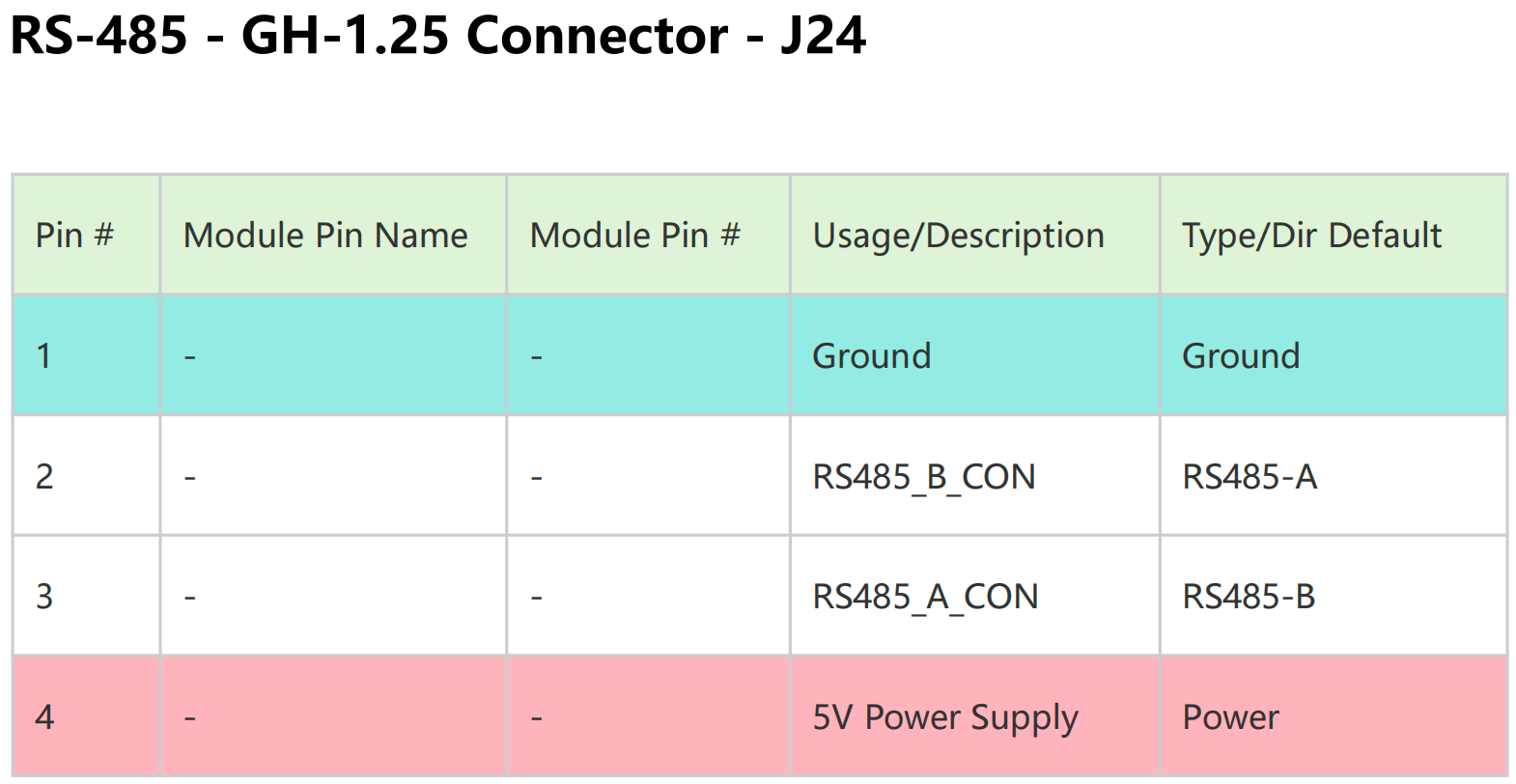
RS485
The reComputer J601 Carrier Board features a dedicated isolated RS-485 port exposed via the J24 JST GH-1.25 4-pin connector. Pin definitions are as follows:
Hardware connection
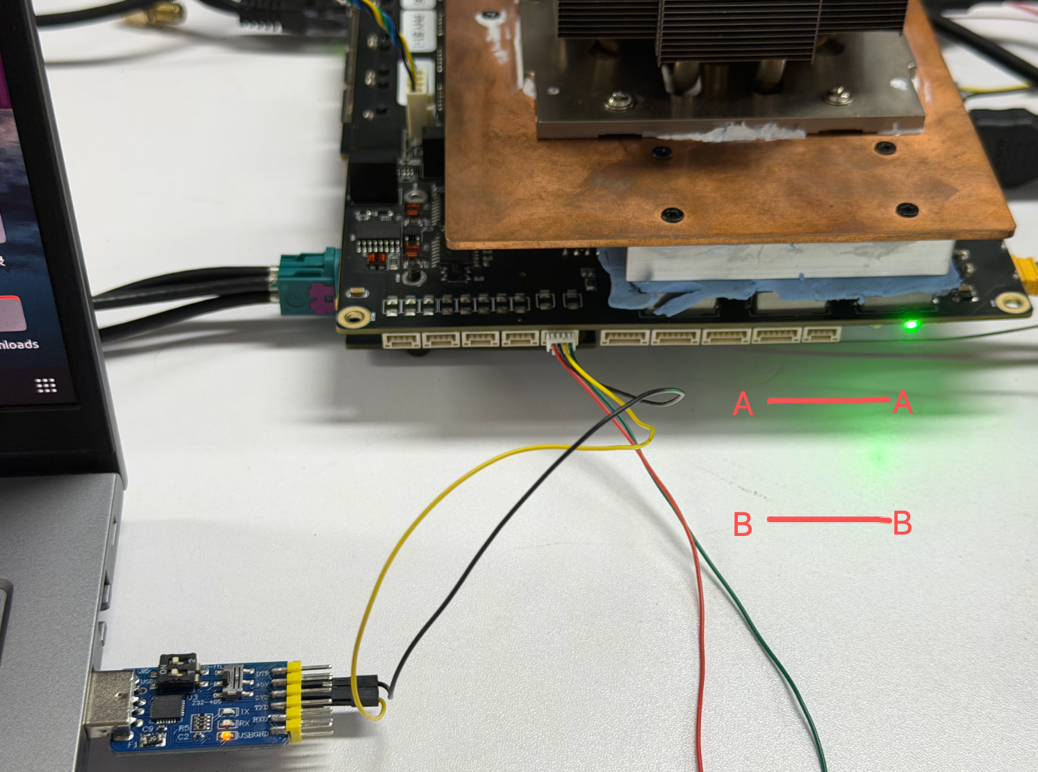
Here we use a usb-to-rs485 to test:
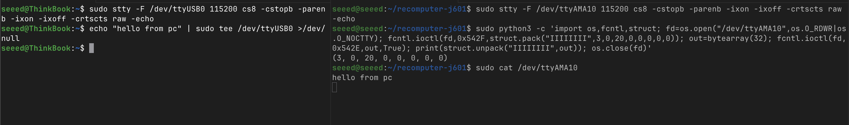
#[Jetson] Init UART: 115200 baud, 8N1, raw mode, no flow control.
sudo stty -F /dev/ttyAMA10 115200 cs8 -cst -parenb -ixon -ixoff -crtscts raw -echo
# [Jetson] Enable and verify RS485 mode via ioctl (TIOCSRS485 / TIOCGRS485).
sudo python3 -c 'import os,fcntl,struct; fd=os.open("/dev/ttyAMA10",os.O_RDWR|os.O_NOCTTY); fcntl.ioctl(fd,0x542F,struct.pack("IIIIIIII",3,0,20,0,0,0,0,0)); out=bytearray(32); fcntl.ioctl(fd,0x542E,out,True); print(struct.unpack("IIIIIIII",out)); os.close(fd)'
# Verification output:(3, 0, 20, 0, 0, 0, 0, 0)
#[PC] Init USB UART with identical parameters.
sudo stty -F /dev/ttyUSB0 115200 cs8 -cstopb -parenb -ixon -ixoff -crtscts raw -echo
#[Jetson] Listen for data.
sudo cat /dev/ttyAMA10
#[PC] Send message.
echo "hello from pc" | sudo tee /dev/ttyUSB0 >/dev/null
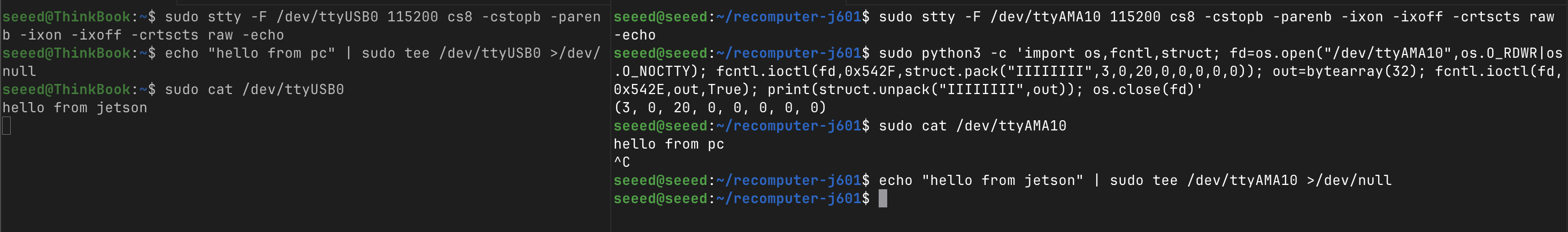
#[PC] Listen for data.
sudo cat /dev/ttyUSB0
#[Jetson] Send message.、
echo "hello from jetson" | sudo tee /dev/ttyAMA10 >/dev/null
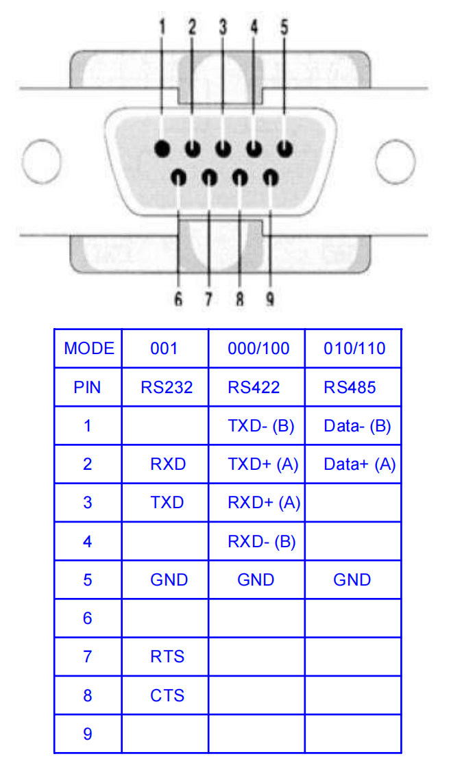
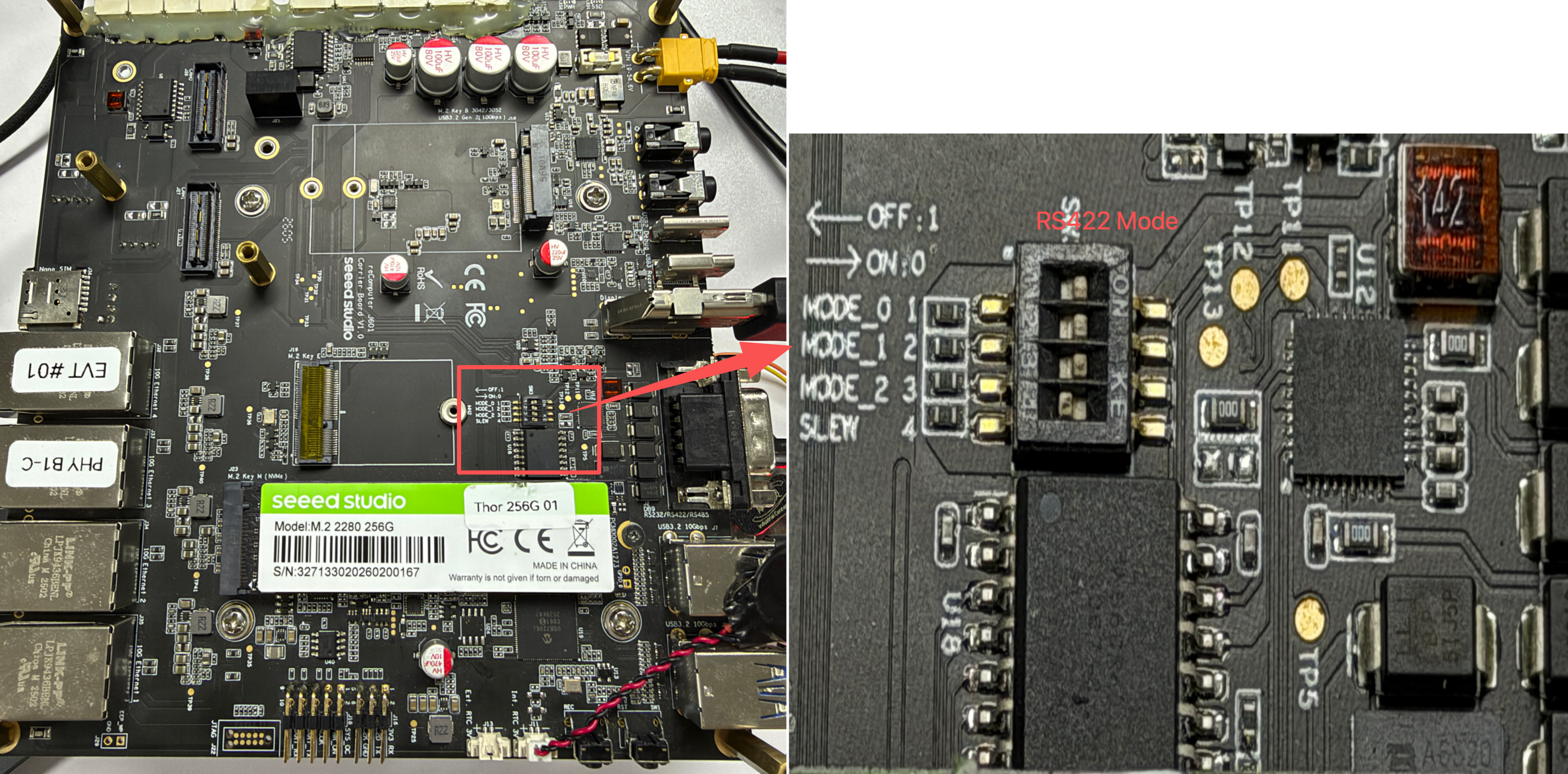
DB9 (RS232 / RS422 / RS485)
The Robotics J601 provides one software-selectable DB9 serial interface. The DB9 port is connected to /dev/ttyAMA9 on the Jetson system and can be configured as RS232, RS422, or RS485 by setting the SW3 DIP switch.
Pin definition
The function of each DB9 pin depends on the selected communication mode. Refer to the table and the connector diagram below before wiring the adapter.
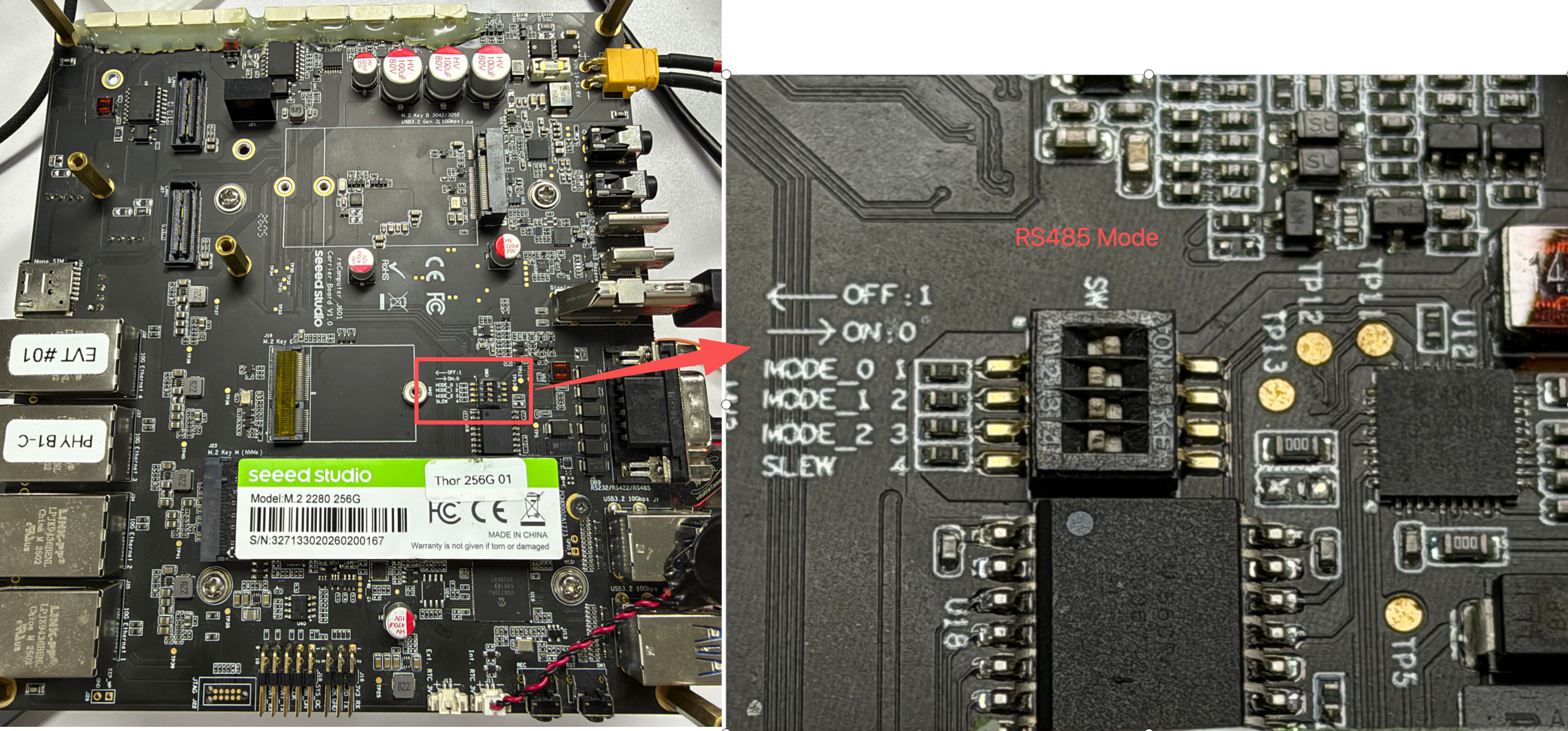
RS485 Mode
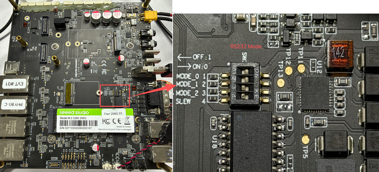
Hardware Configuration
Switch the switch at the bottom of the board to the RS485 mode as shown in the figure below.
Hardware connection
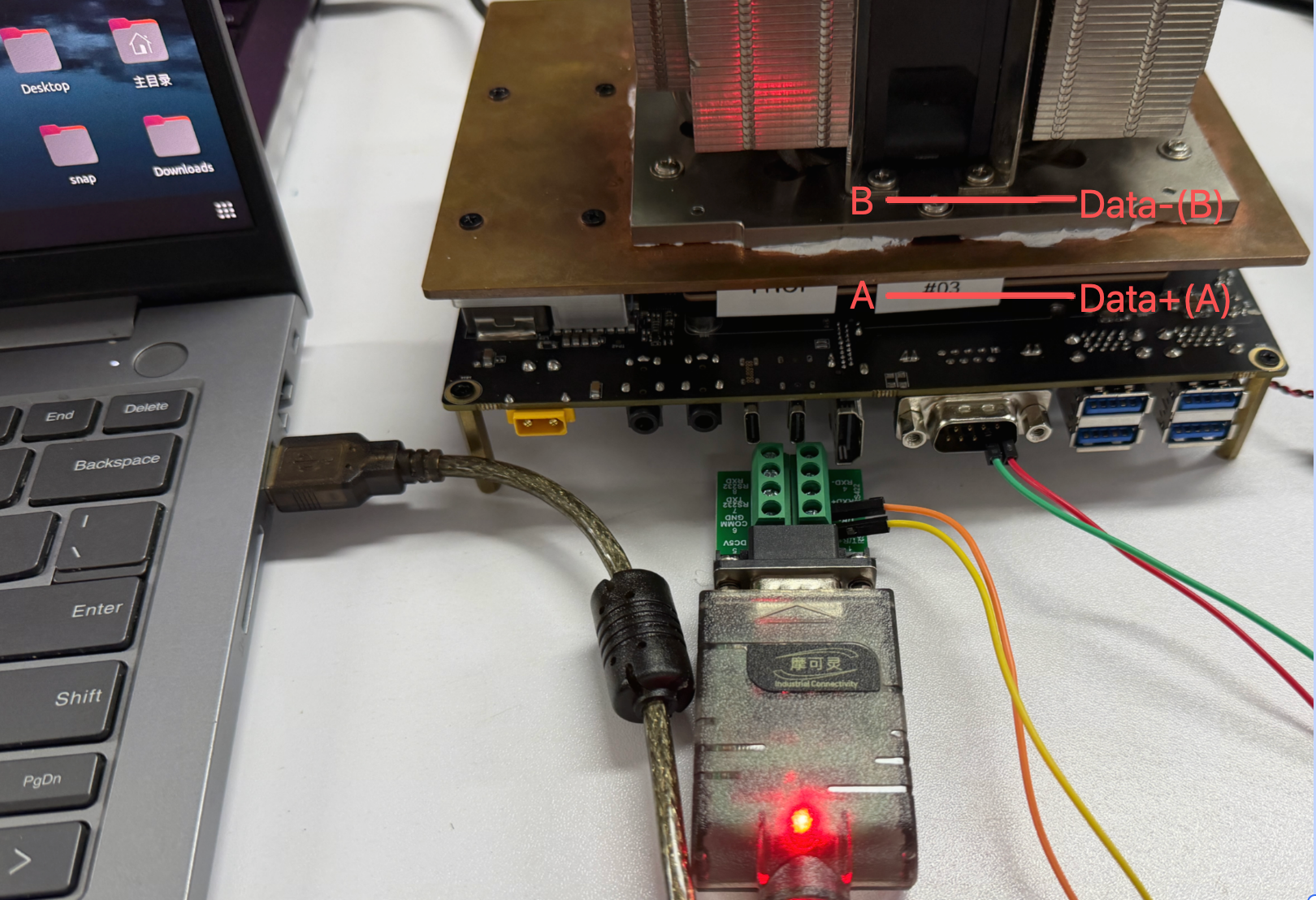
For RS485 wiring, connect the USB-RS485 adapter A/D+ to DB9 pin 2, B/D- to DB9 pin 1. Some USB-RS485 adapters label A/B in the opposite way. If the Jetson receives random bytes while the PC is not sending, swap A and B and test again.
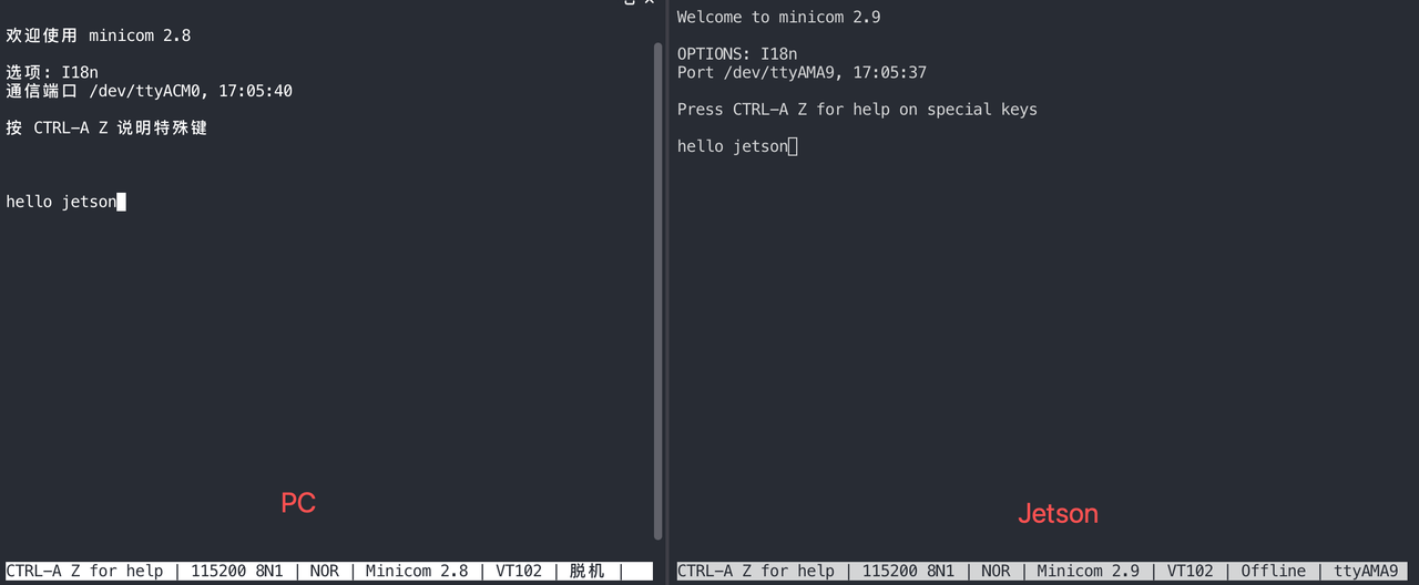
Communication Test
Here, we use minicom to conduct the test:
# Set pin 6 on GPIO chip 3 to low level to enable the DB9 transceiver
sudo gpioset 3 6=0

# On Jetson terminal
sudo minicom -D /dev/ttyAMA9 -b 115200

# On PC terminal
sudo minicom -D /dev/ttyACM0 -b 115200
To see the text you type in minicom, you need to enable the Local Echo feature. By default, minicom does not display your keystrokes, so this is a very common issue.
- step 1. Press
Ctrl+A - step 2. Then, press
E
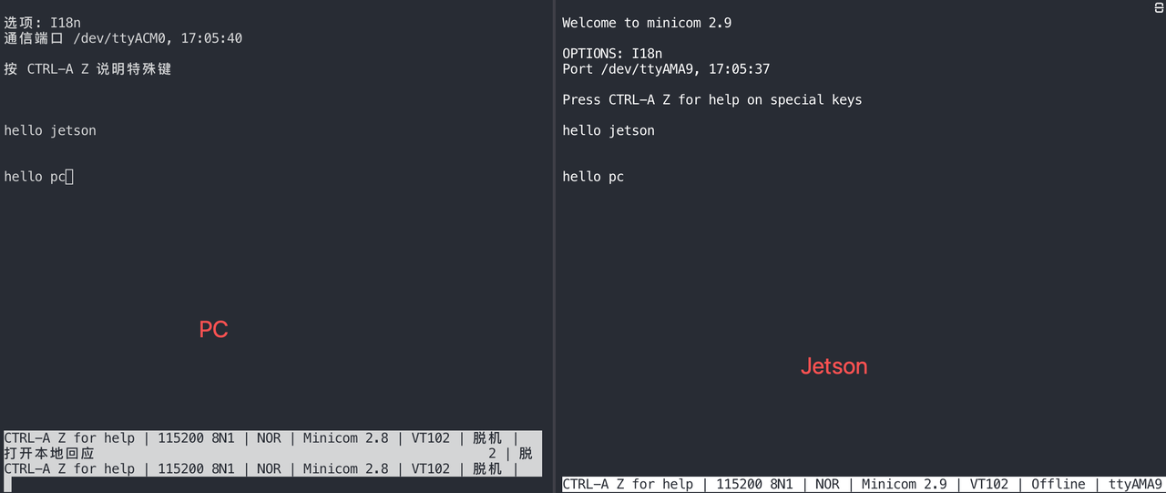
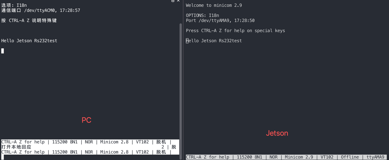
Test the PC to send a message to Jetson.
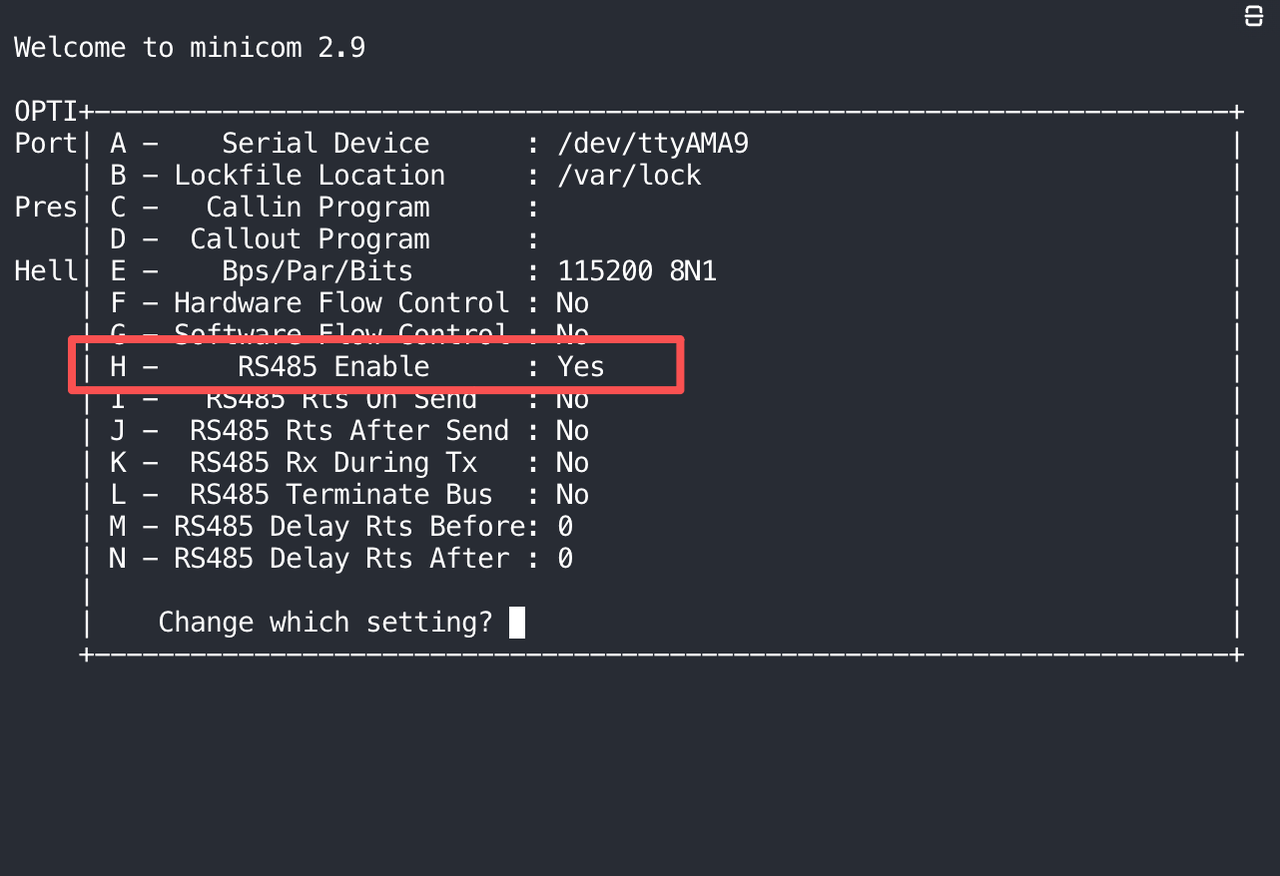
Since RS485 is a half-duplex protocol, in order to test that Jetson can send information to the PC via RS485, it is necessary to activate the RS485 mode.
- step 1. Press
Ctrl+A - step 2. Then, press
Oopen the config option.
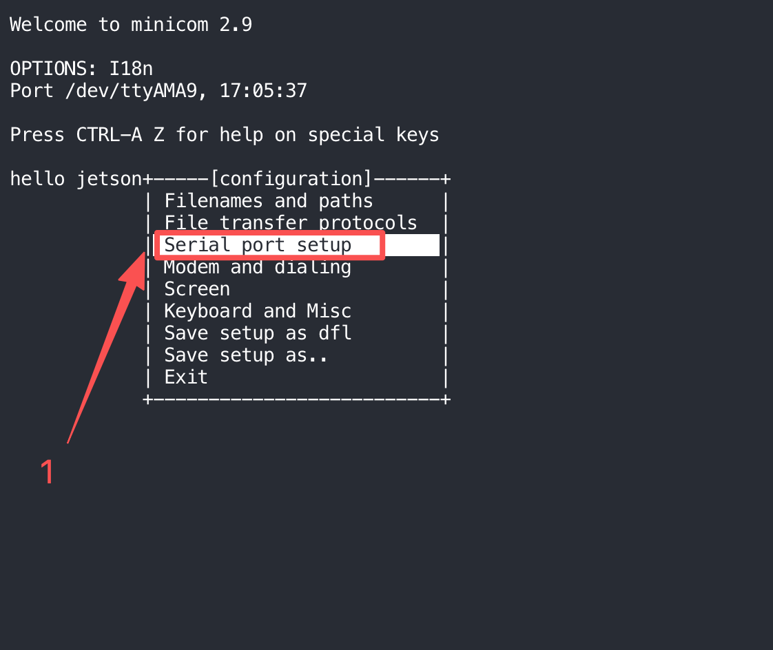
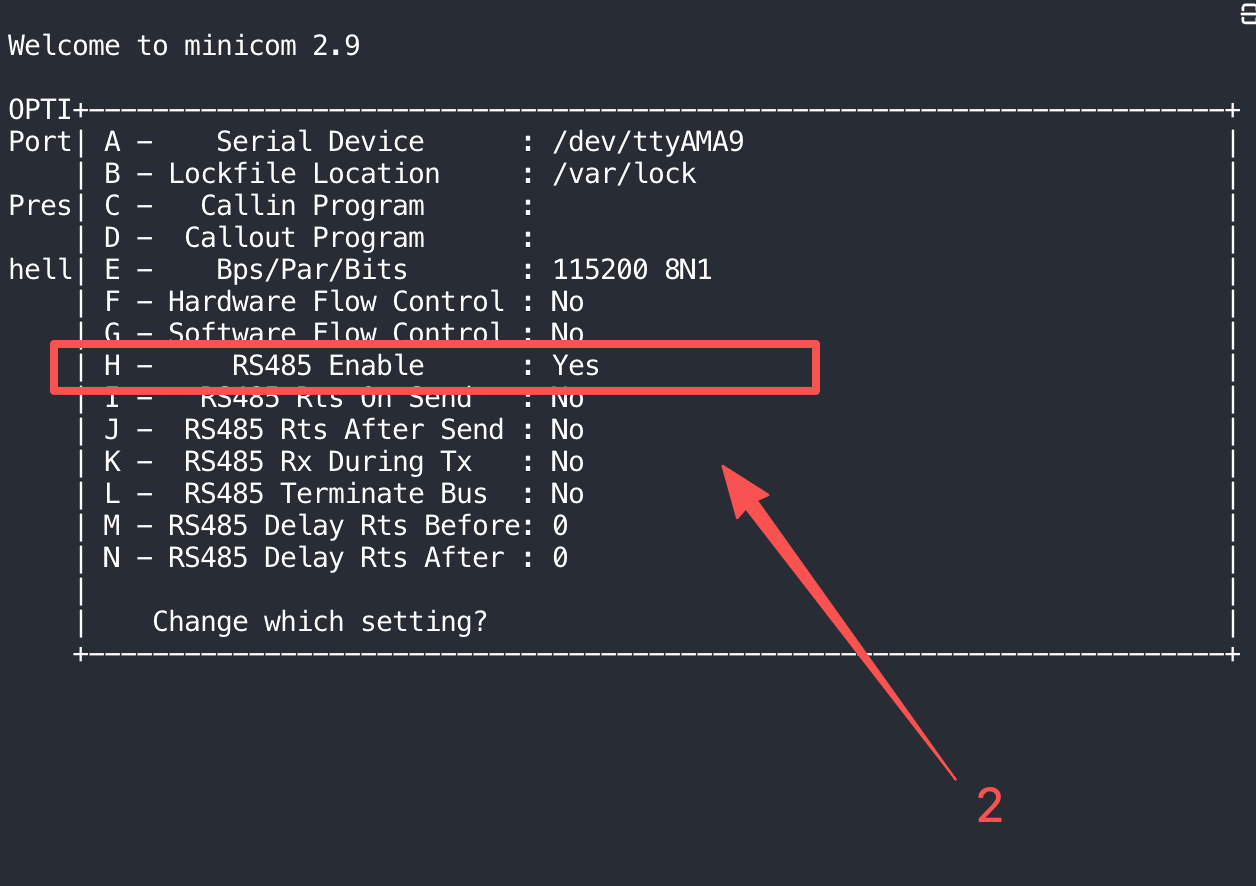
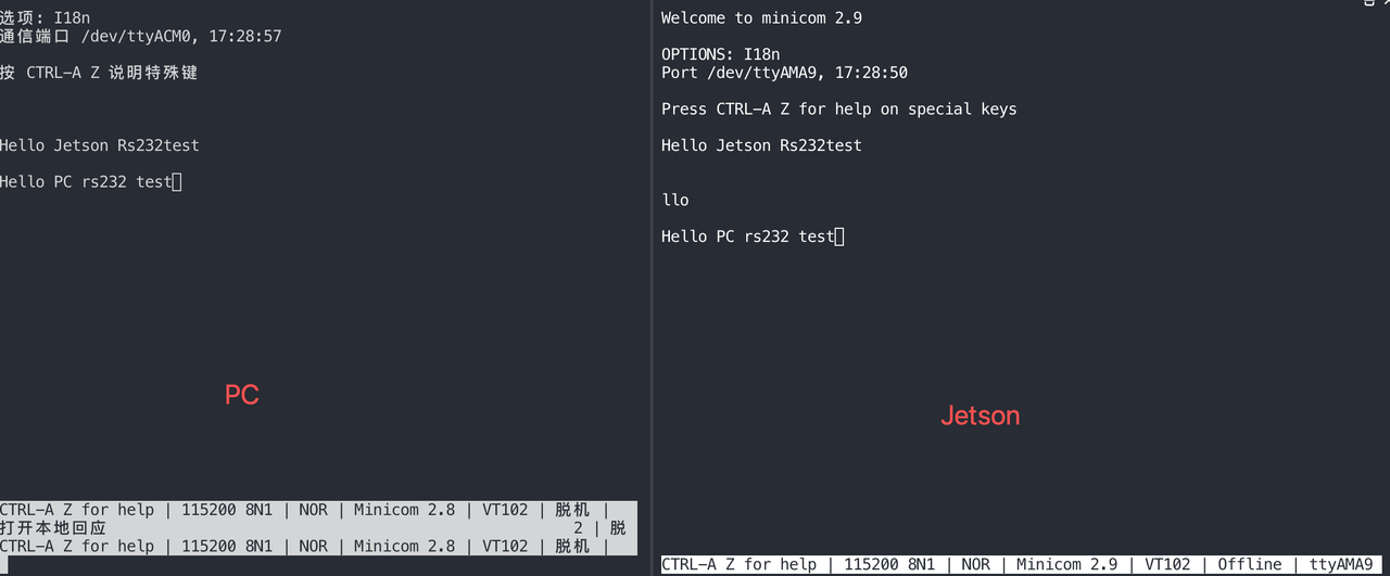
Finally, you will be able to send messages from Jetson to your PC.
RS232 Mode
Hardware Configuration
Switch the switch at the bottom of the board to the RS232 mode as shown in the figure below.
Hardware connection
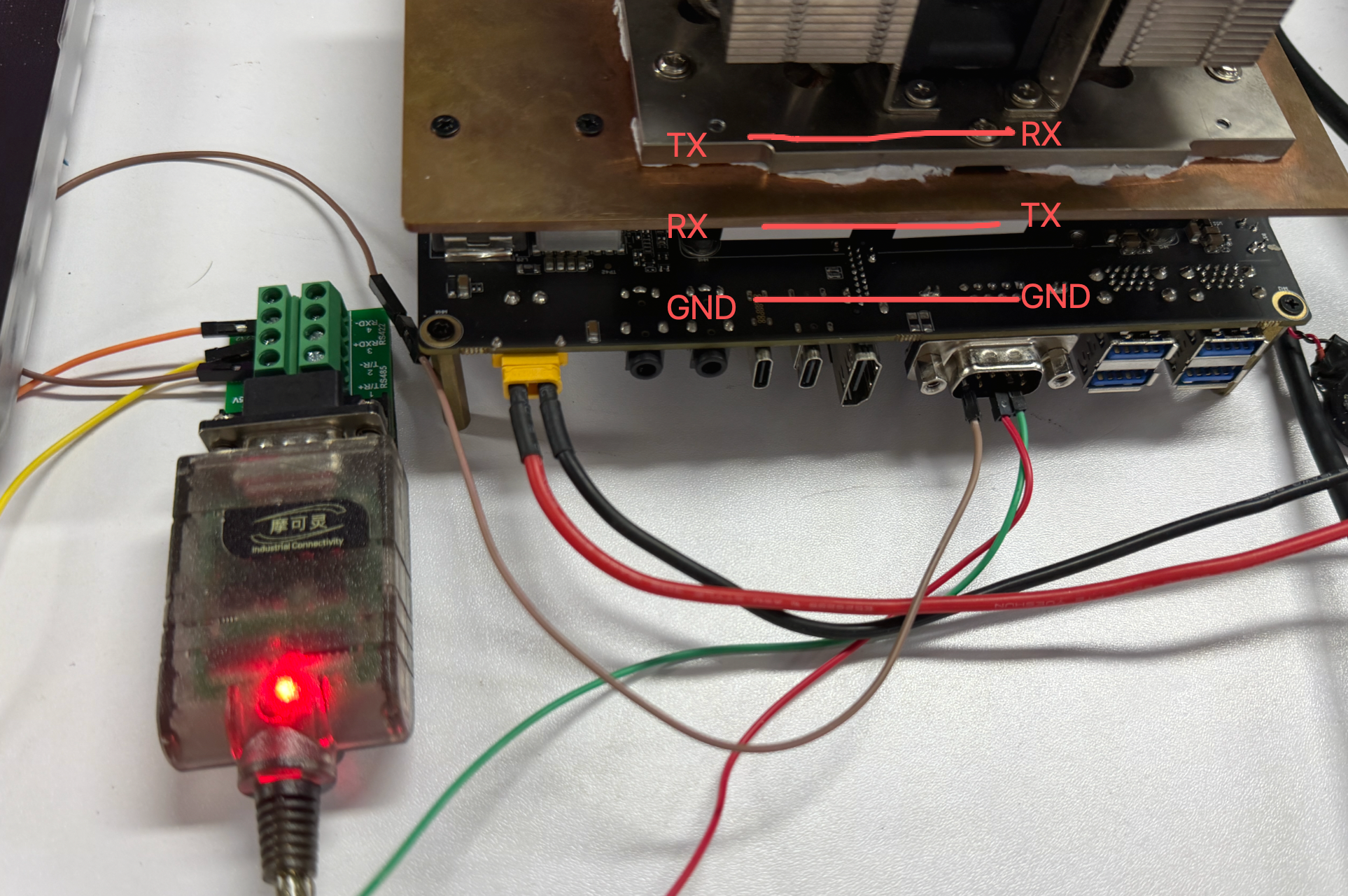
- TX → RX
- RX → TX
- GND → GND
Communication Test
Here, we use minicom to conduct the test:
# Set pin 6 on GPIO chip 3 to low level to enable the DB9 transceiver
sudo gpioset 3 6=0

# On Jetson terminal
sudo minicom -D /dev/ttyAMA9 -b 115200

# On PC terminal
sudo minicom -D /dev/ttyACM0 -b 115200
To see the text you type in minicom, you need to enable the Local Echo feature. By default, minicom does not display your keystrokes, so this is a very common issue.
- step 1. Press
Ctrl+A - step 2. Then, press
E
Test the PC to send a message to Jetson.
Also turn on the test mode.
Send messages from Jetson to your PC.
RS422 Mode
Hardware Configuration
Switch the switch at the bottom of the board to the RS422 mode as shown in the figure below.
Hardware connection
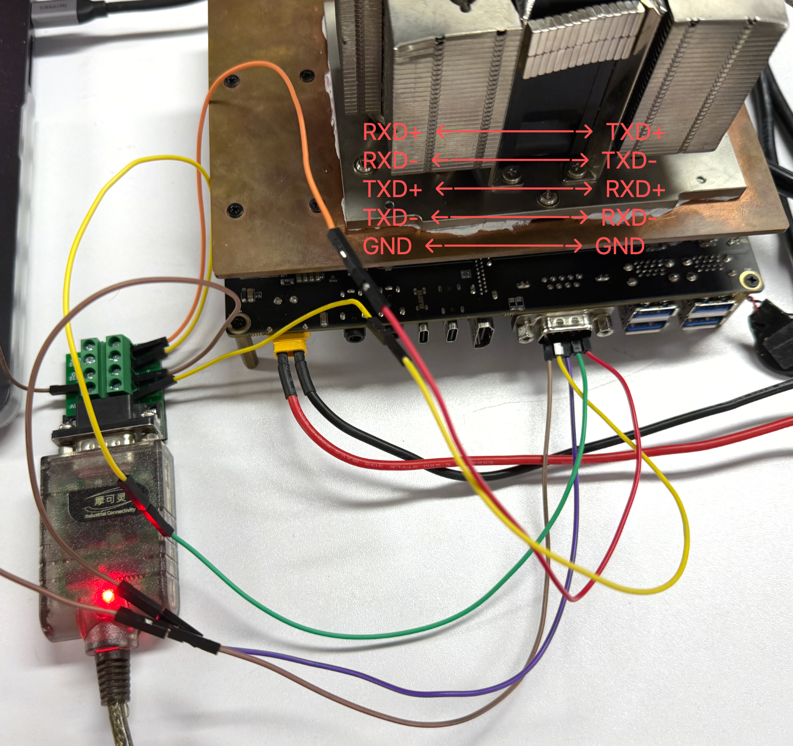
- RXD+ ←─────→ TXD+
- RXD- ←─────→ TXD-
- TXD+ ←─────→ RXD+
- TXD- ←─────→ RXD-
- GND ←─────→ GND
Communication Test
Here, we use minicom to conduct the test:
# Set pin 6 on GPIO chip 3 to low level to enable the DB9 transceiver
sudo gpioset 3 6=0

# On Jetson terminal
sudo minicom -D /dev/ttyAMA9 -b 115200

# On PC terminal
sudo minicom -D /dev/ttyACM0 -b 115200
To see the text you type in minicom, you need to enable the Local Echo feature. By default, minicom does not display your keystrokes, so this is a very common issue.
- step 1. Press
Ctrl+A - step 2. Then, press
E
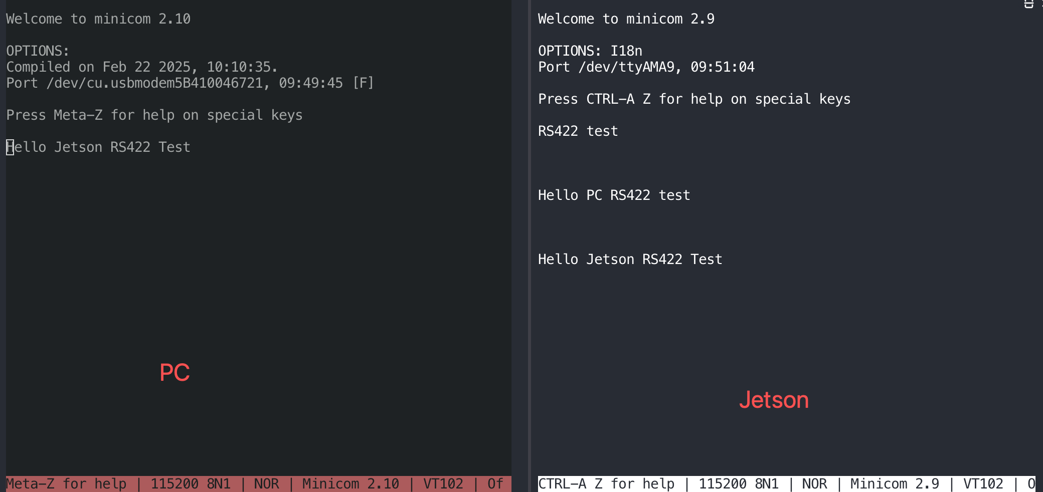
Test the PC to send a message to Jetson.
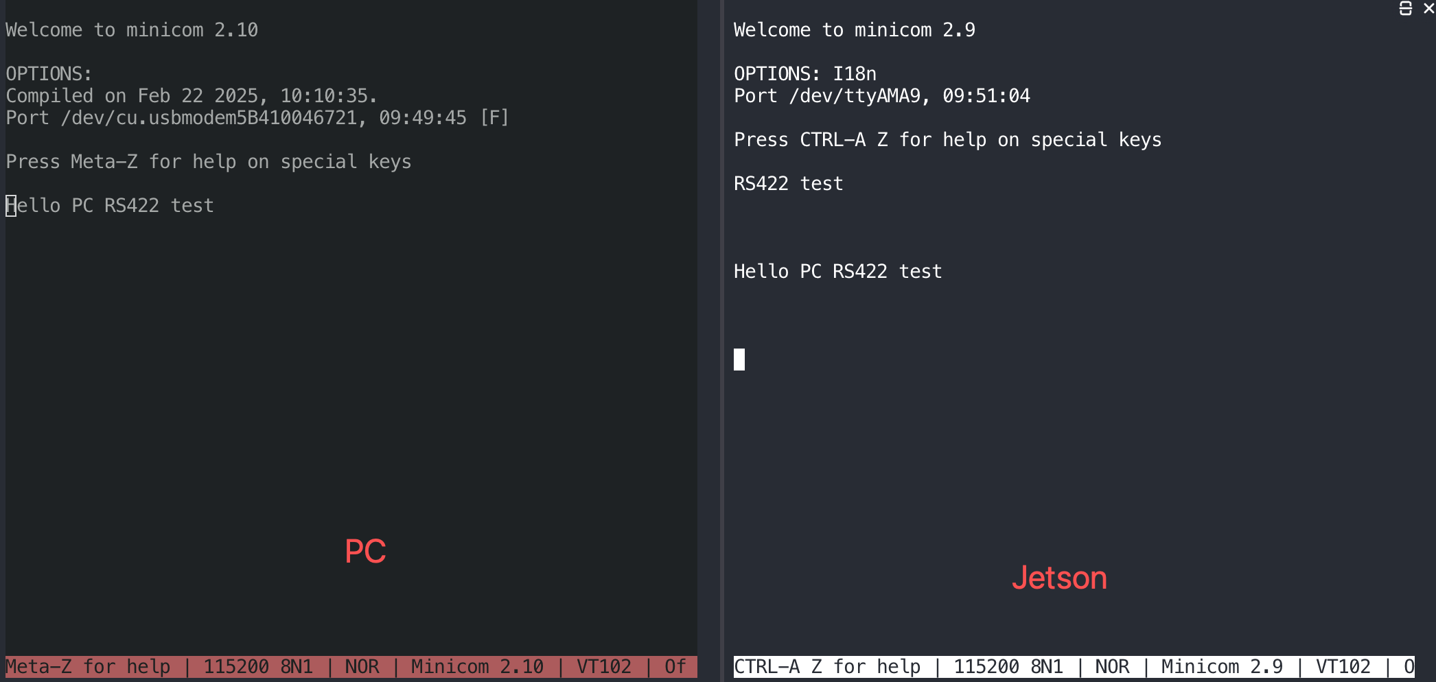
Also turn on the test mode.
RGB
test_rgb.sh
#!/bin/bash

# ==============================================================================
# Script Name: test_rgb.sh
# Target Platform: Seeed reComputer J601 (Jetson)
# Description: Automatically tests RGB LEDs by lighting up Red, Green, Blue,
#              and White colors sequentially for 1 second each.
# Usage: sudo ./test_rgb.sh
# ==============================================================================

# Define LED paths
LED_DIR="/sys/class/leds"
RED="$LED_DIR/red/brightness"
GREEN="$LED_DIR/green/brightness"
BLUE="$LED_DIR/blue/brightness"

# Check if running as root (sysfs write access requires root privileges)
if [ "$EUID" -ne 0 ]; then
    echo "Error: Please run this script with sudo!"
    echo "Example: sudo $0"
    exit 1
fi

# Check if the hardware paths exist
if [ ! -d "$LED_DIR/red" ] || [ ! -d "$LED_DIR/green" ] || [ ! -d "$LED_DIR/blue" ]; then
    echo "Error: RGB LED hardware paths not found. Please check your driver or device model."
    exit 1
fi

# Helper function: Control LED states
# Arguments: set_leds <Red(0/1)> <Green(0/1)> <Blue(0/1)>
set_leds() {
    echo "$1" > "$RED"
    echo "$2" > "$GREEN"
    echo "$3" > "$BLUE"
}

echo "========================================"
echo "         Starting Jetson RGB LED Test    "
echo "========================================"

# 1. Initialization: Turn off all LEDs
echo "-> Initializing: Turning off all LEDs"
set_leds 0 0 0
sleep 0.5

# 2. Red LED on for 1 second
echo "-> [ON] Red Light"
set_leds 1 0 0
sleep 1

# 3. Green LED on for 1 second
echo "-> [ON] Green Light"
set_leds 0 1 0
sleep 1

# 4. Blue LED on for 1 second
echo "-> [ON] Blue Light"
set_leds 0 0 1
sleep 1

# 5. Mixed White LED on for 1 second (Red + Green + Blue mixed)
echo "-> [ON] White Light (RGB Mixed)"
set_leds 1 1 1
sleep 1

# 6. Test completed, turn off all LEDs
echo "-> Test completed: Turning off all LEDs"
set_leds 0 0 0

echo "========================================"
echo "             LED Test Ended             "
echo "========================================"
sudo chmod +x test_rgb.sh
sudo ./test_rgb.sh
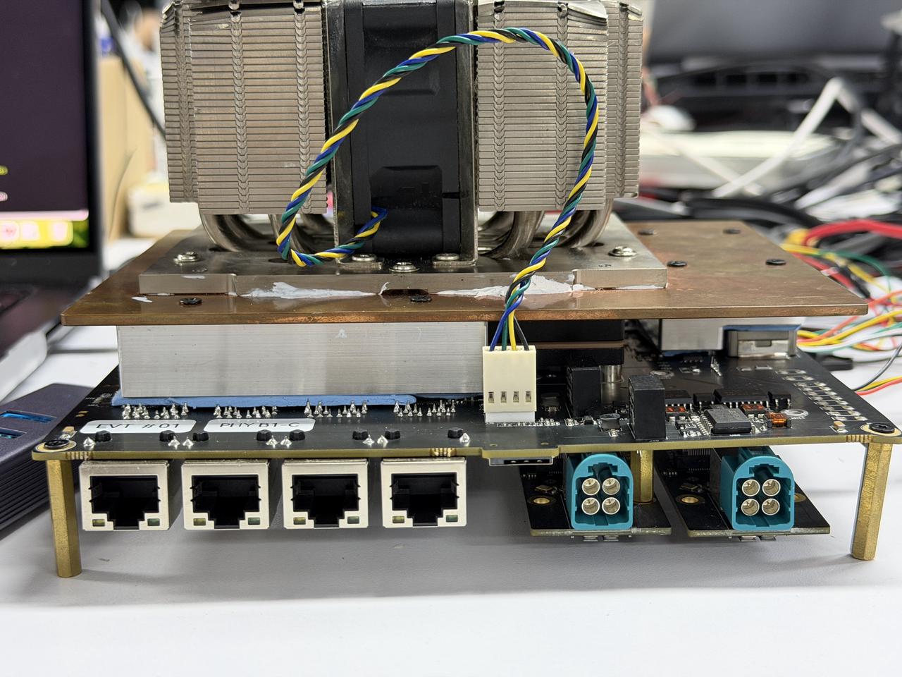
Ethernet
The Robotics J601 carrier board features 4x 10GbE RJ45 Ethernet ports for wired network connectivity, with planned support for PTP and EtherCAT protocols. (Note: T4000 modules support 3x 10GbE.)
Hardware Connection
Usage Instruction
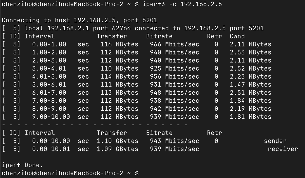
To test Ethernet port speed, use iperf3 as follows:
Upload speed test:
iperf3 -c <server_ip> -B <bind_ip>
Download speed test:
iperf3 -c <server_ip> -B <bind_ip> -R
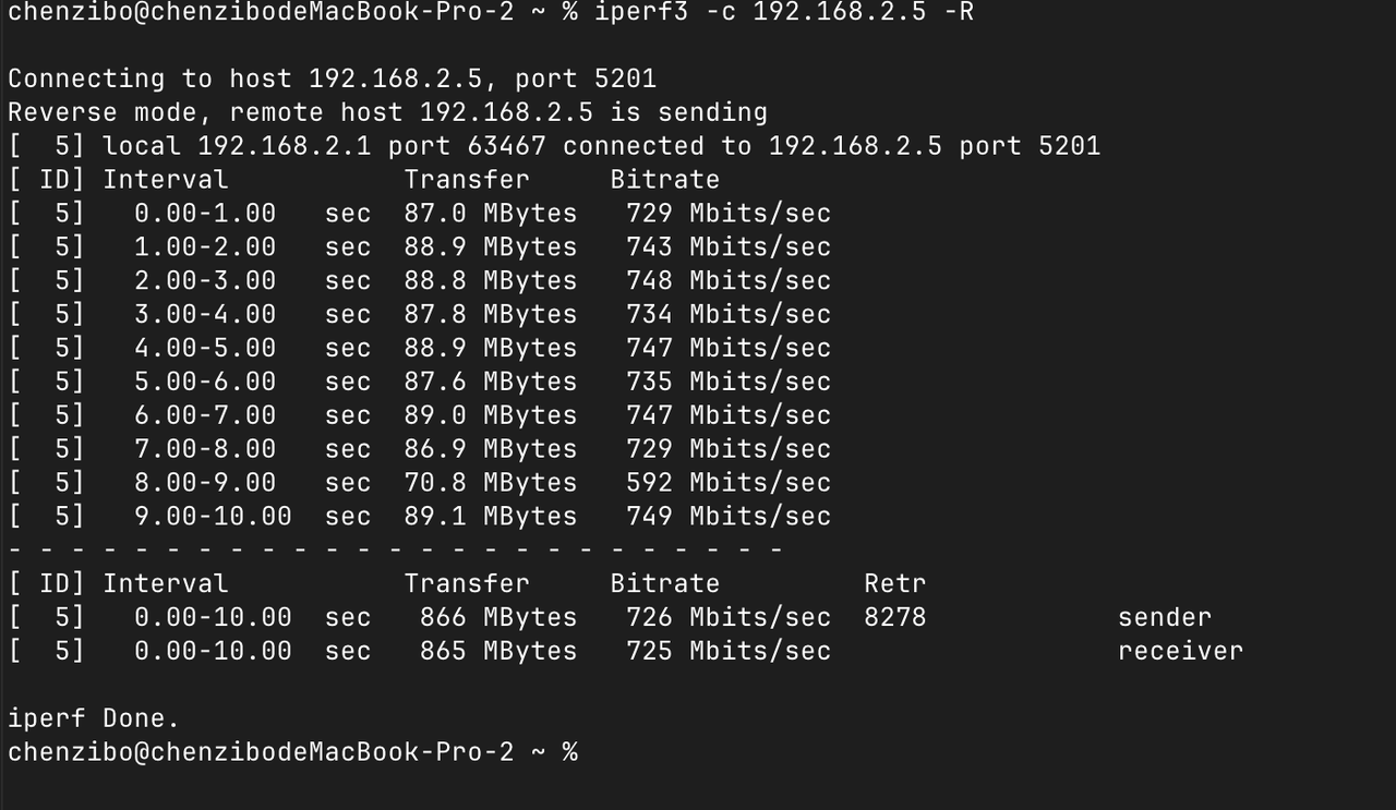
<server_ip>is the IP address of the iperf3 server. The client will connect to this server to perform a bandwidth test.<bind_ip>binds the specified local IP address as the source of the test traffic.- The
-Rflag reverses the test direction for download speed testing.
M.2 Key E
The M.2 Key E interface is a standard M.2 connector primarily used for connecting wireless modules, such as Wi-Fi and Bluetooth, to expand wireless communication capabilities.
Hardware Connection
Usage Instruction
Step 1. Install the Wi-Fi driver firmware:
# Decompress firmware files
cd /lib/firmware/rtw88/
sudo zstd -d rtw8822c_fw.bin.zst -o rtw8822c_fw.bin
sudo zstd -d rtw8822c_wow_fw.bin.zst -o rtw8822c_wow_fw.bin

# Load the driver modules
sudo modprobe rtw88_core
sudo modprobe rtw88_pci
sudo modprobe rtw88_8822c
sudo modprobe rtw88_8822ce
Step 2. Reboot the device:
sudo reboot
Step 3. After reboot, bring up the wireless interface:
sudo ip link set wlP1p1s0 up
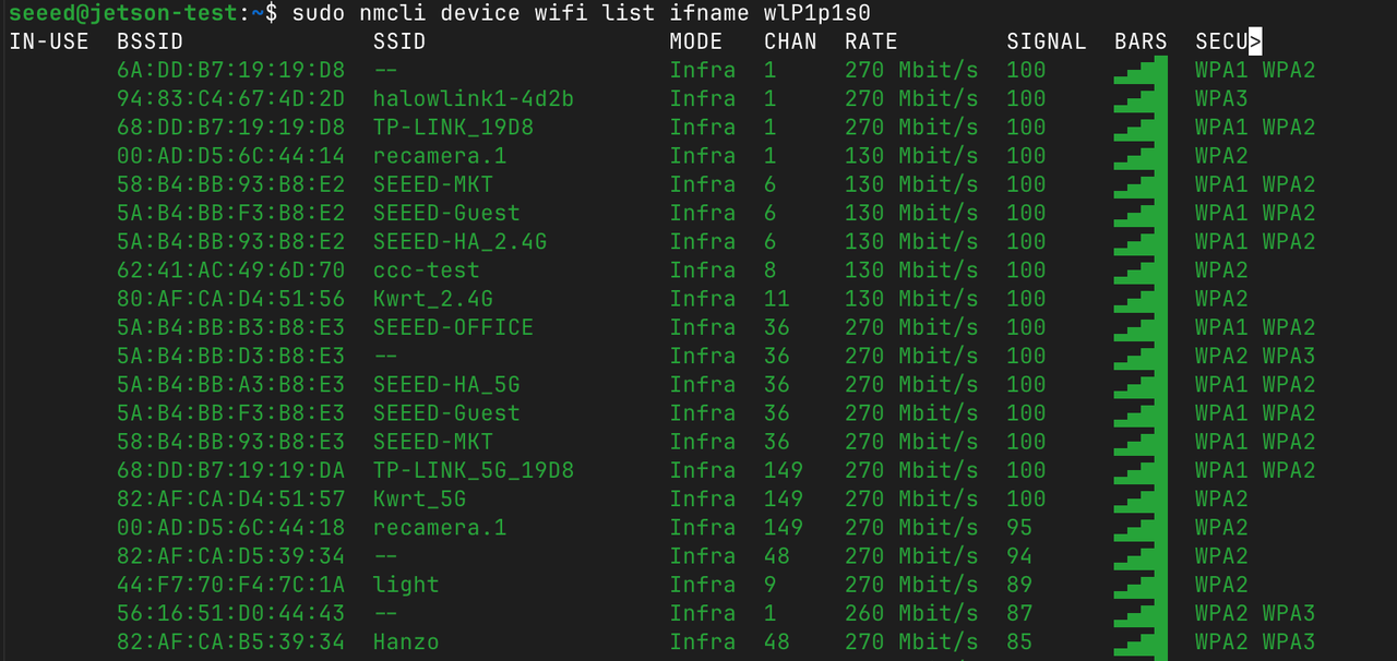
Step 4. Scan for available Wi-Fi networks:
sudo nmcli device wifi list ifname wlP1p1s0
Step 5. Connect to a Wi-Fi network:
sudo nmcli device wifi connect "your WiFi name" password "WiFi password" ifname wlP1p1s0

Bluetooth
Bluetooth functionality is available via the M.2 Key E slot.
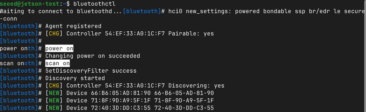
Step 1. Open the Bluetooth control tool:
bluetoothctl
Step 2. Power on and scan for nearby Bluetooth devices:
power on
scan on
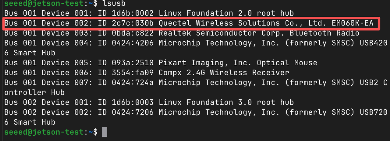
5G Module (M.2 Key B)
The M.2 Key B slot supports 5G module expansion, enabling high-speed cellular connectivity for robotics and edge AI scenarios.
Hardware Connection
Install the 5G module into the M.2 Key B slot and connect the antennas.
Usage Instruction
Step 1. Open the 5G module serial console:
sudo apt install -y minicom
sudo minicom -D /dev/ttyUSB3
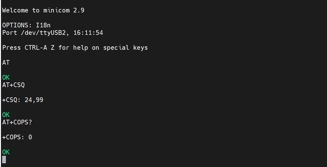
Step 2. Enter interactive mode by pressing Ctrl+A then E.
Step 3. Test AT commands:
AT
Step 4. Check signal strength:
AT+CSQ
Step 5. Check the registered network operator:
AT+COPS?
Nano SIM
GPS
The 5G module on the M.2 Key B slot also provides GPS functionality for location tracking.
Usage Instruction
Step 1. Open the GPS AT command port:
sudo minicom -D /dev/ttyUSB2 -b 115200
Step 2. Enable the GPS receiver:
AT+QGPS=1
- If the response is
OK, the GPS receiver has been successfully started. - If the response is
+CME ERROR: 549, GPS is already enabled — no need to enable it again.
Step 3. Exit minicom by pressing Ctrl+A then X, and select Yes to exit.
Step 4. After GPS is enabled, satellite data will stream from the GPS data port (typically /dev/ttyUSB1). Read the raw NMEA data:
sudo cat /dev/ttyUSB1
You should see standard GPS NMEA sentences such as:
$GPRMC,023011.00,A,2232.12345,N,11356.54321,E,0.026,,100626,,,A*7A
$GPGGA,023011.00,2232.12345,N,11356.54321,E,1,06,1.2,45.3,M,-2.3,M,,*6D
$GPGSV,3,1,11,01,65,120,42,03,45,210,38,08,30,045,35,11,15,290,31*74
Ensure you have a clear view of the sky for GPS signal acquisition. It may take a few minutes to get a valid fix.
Resources
Tech Support & Product Discussion
Thank you for choosing our products! We are here to provide you with different support to ensure that your experience with our products is as smooth as possible. We offer several communication channels to cater to different preferences and needs.