reComputer Super Hardware and Interfaces Usage

This wiki introduces the various different hardware and interfaces on the reComputer Super and how to use them to expand your project ideas.
CSI Camera
The reComputer Super supports standard 4 MIPI CSI cameras for image and video capture. Please follow the steps below to connect and test your camera.
Hardware Connection

Step1. Open the back cover of the Recomputer Super.
Step2. Connect the MIPI CSI camera to the appropriate CSI port on the reComputer Super board.
Step3. Secure the camera and ensure the connection is firm.
Usage Instruction
Before using the CSI camera, please ensure you have installed a JetPack version with the necessary camera drivers.
Step1. Check if the camera is recognized by the system:
ls /dev/video*
Step2. (Optional) Install video utilities if not already present:
sudo apt install v4l-utils
Step3. Start the camera and display the video stream using the following command:
nvgstcapture-1.0 --sensor-id=0
Change --sensor-id to the appropriate value if you have multiple cameras.

USB
The reComputer Super has a total of 4 USB 3.2 ports and 1 USB 2.0 Type-C port for debugging.
USB 3.2 port
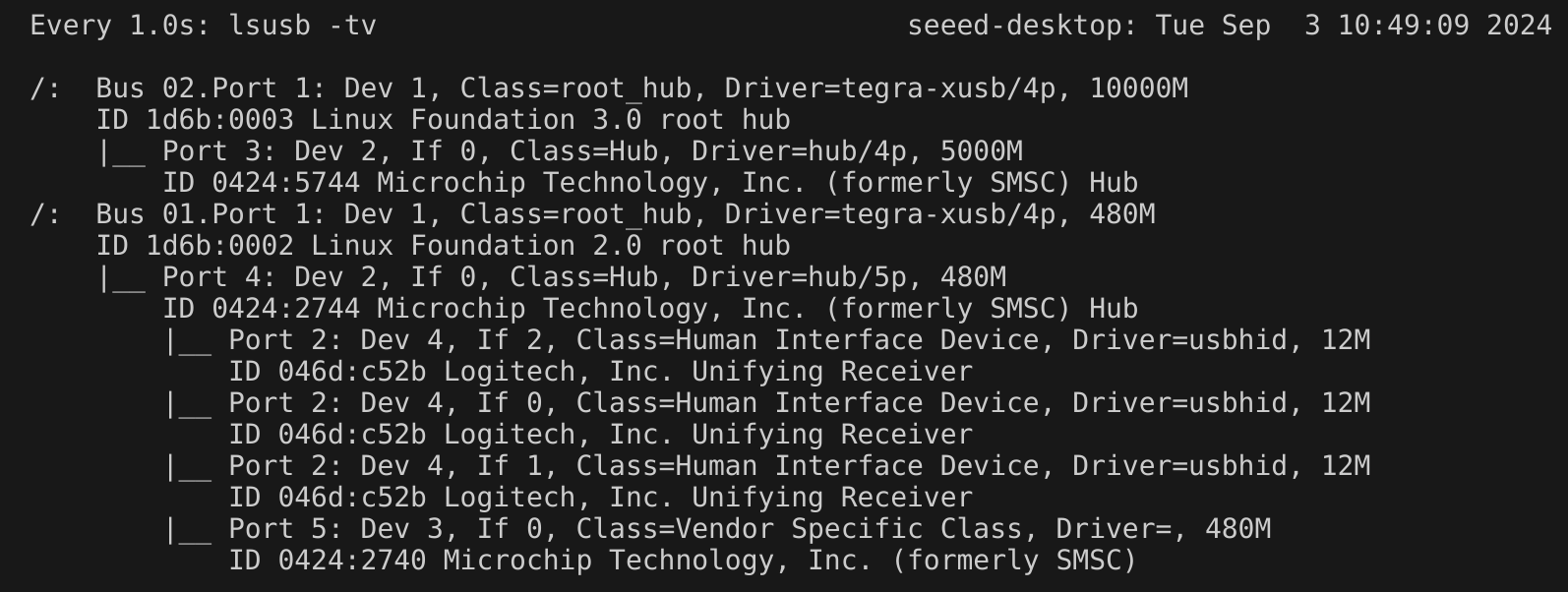
We can enter watch -n 1 lsusb -tv in the Jetson terminal to probe the USB ports. Once a USB device is connected, the detailed information about that port will be displayed here.
Additionally, you can test the read and write speed of USB storage devices by using the dd command:
-
Read:
sudo dd if=/dev/sda of=/dev/null bs=1024M count=5 iflag=direct

-
Write:
sudo dd if=/dev/zero of=/dev/sda bs=1024M count=5 conv=fdatasync

USB 2.0 Type-C port
Using this serial port, via the USB C data cable, you can monitor the debugging information of input and output on the PC side.
Step1. Switch the switch to the debug mode.

Step2. Connect the PC via a USB data cable, downloaded the CP210X Driver on your PC.

Step3. Connect the PC via a USB data cable, extract the downloaded file and install driver on your PC.

Step4. Open Open the Device Manager on your Windows PC and check the COM port number assigned to the reComputer Super. It should appear under "Ports (COM & LPT)" as "Silicon Labs CP210x USB to UART Bridge (COMX)", where X is the COM port number.

Step5. Open the serial port tool(Here, we use the MobaXterm tool as an example), create a new session.

Step6. Select the Serial tool.

Step7. Select corresponding serial port, set the baud rate to 115200 and click "OK".

Step8. Login your reComputer Super with the username and password.

M.2 Key M
M.2 Key M is an interface designed for high-speed solid-state drives (SSDs), providing ultra-fast data transfer speeds, ideal for high-performance applications.
Supported SSD are as follows
- 128GB NVMe M.2 PCle Gen3x4 2280 Internal SSD
- 256GB NVMe M.2 PCle Gen3x4 2280 Internal SSD
- 512GB NVMe M.2 PCle Gen3x4 2280 Internal SSD
- 1TB NVMe M.2 PCle Gen3x4 2280 Internal SSD
- 2TB NVMe M.2 PCle Gen3x4 2280 Internal SSD
Hardware Connection

Usage Instruction
Open the terminal in Jetson device and enter the following command to test the SSD's read and write speed.
#create a blank test file first
sudo touch /ssd/test
dd if=/dev/zero of=/home/seeed/ssd/test bs=1024M count=5 conv=fdatasync

Please run sudo rm /home/seeed/ssd/test command to delete the cache files after the test is complete.
M.2 Key E
The M.2 Key E interface is a compact, high-speed data interface designed for wireless communication modules such as Wi-Fi and Bluetooth, used to expand wireless capabilities.
Hardware Connection

Usage Instruction
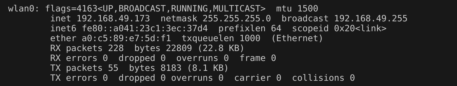
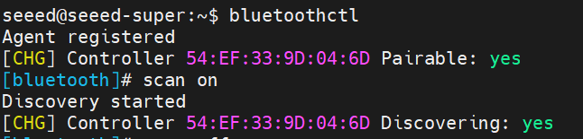
After installing the Wi-Fi module and powering on the device, we can configure the device's Wi-Fi and Bluetooth settings.
Of course, we can also check the device's operating status using the following commands.
ifconfig
Bluetooth:
bluetoothctl
scan on
Mini PCIe
The reComputer super comes with a mini-PCIe for LTE 4G module.
Hardware Connection

If you want to remove the SIM card, push the card in to hit the internal spring so that the SIM will come out of the slot
Usage Instruction
Step1. Install minicom:
sudo apt update
sudo apt install minicom -y
Step2. Enter the serial console of the connected 4G module so that we can enter AT commands and interact with the 4G module:
sudo minicom -D /dev/ttyUSB2 -b 115200
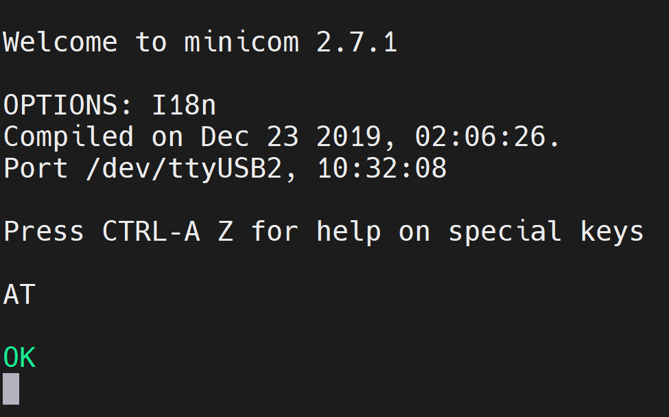
Step3. Press Ctrl+A and then press E to turn on local echo.
Step4. Enter the command "AT" and press enter. If you see the response as "OK", the 4G module is working properly.
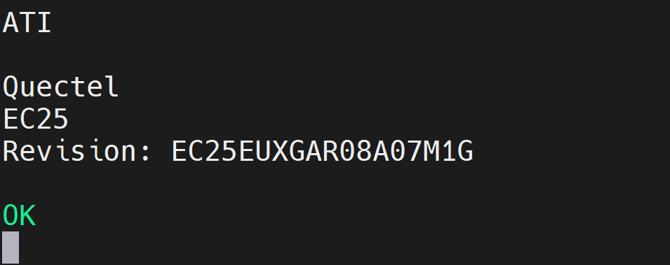
Step5. Enter the command "ATI" to check the module information.
Using 4G network for internet access

RTC
The reComputer Super features RTC interfaces, providing accurate timekeeping even when the system is powered off.
Hardware Connection
Connect a 3V CR1225 coin cell battery to the RTC socket on the board as shown below. Make sure the positive (+) end of the battery is facing upwards.

Usage Instruction
Step1. Connect an RTC battery as mentioned above.
Step2. Turn on reComputer Super.
Step3. On the Ubuntu Desktop, click the drop-down menu at the top right corner, navigate to Settings > Date & Time, connect to a network via an Ethernet cable and select Automatic Date & Time to obtain the date/ time automatically.
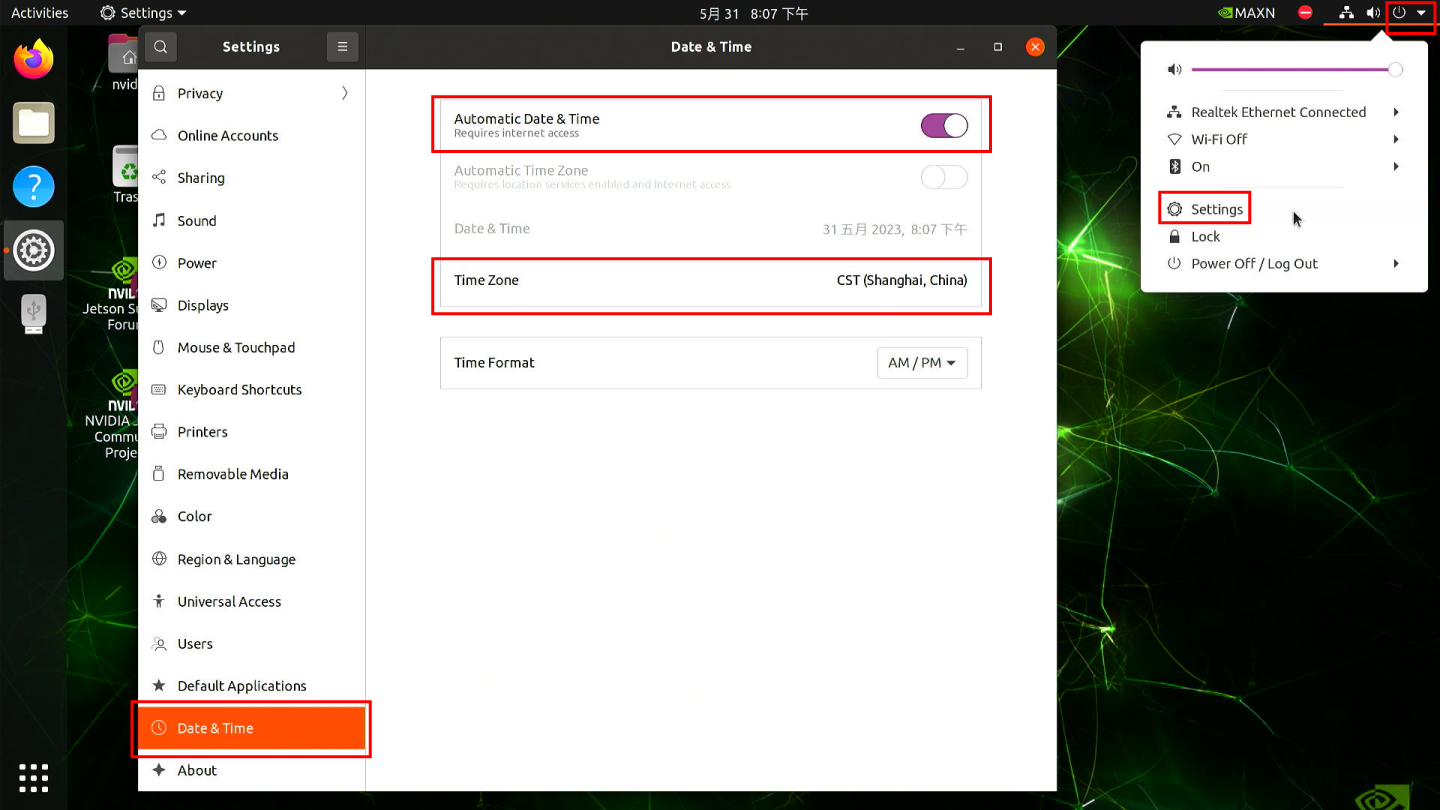
If you have not connected to internet via Ethernet, you can manually set the date/ time here.
Step4. Open a terminal window, and execute the below command to check the hardware clock time:
cat /sys/devices/platform/bpmp/bpmp\:i2c/i2c-4/4-003c/nvvrs-pseq-rtc/rtc/rtc0/time
.png)
Step5. Disconnect the network connection and reboot the device. You will find that the system time has lost power but still functions normally.

Ethernet
There are 2 RJ45 Gigabit Ethernet on reComputer Super supported 10/100/1000M. ETH0 is the native Ethernet port, and the other one ETH1 is converted from PCIe.

There are 2 LEDs (green and yellow) on each Ethernet port:
- Green LED: ON only when connected to 1000M/10G network.
- Yellow LED: Shows the network activity status.
Test the Ethernet speed:
iperf3 -c 192.168.254.100 -R
-c <ip address> is the server IP address, and -R means reverse mode.

iperf3 -c 192.168.254.100

LED Indicators
The reComputer Super is equipped with 2 LED indicators (PWR and ACT) to show power status and system activity, allowing users to monitor device operation in real time.

Fan
The reComputer Super is equipped with two types of fan connectors to meet different voltage and cooling needs:
-
1x 4-Pin Fan Connector (5V PWM): Designed for low-voltage, low-power silent fans, this connector supports PWM speed control, allowing intelligent fan speed adjustment based on system temperature to improve energy efficiency and reduce noise.
-
1x 4-Pin Fan Connector (12V PWM): Compatible with standard 12V PWM fans, it also supports precise speed control, making it ideal for high-performance cooling requirements.
Hardware Connection

For more information, please check here.
Set fan speed:
sudo -i
echo 100 > /sys/bus/platform/devices/pwm-fan/hwmon/hwmon1/pwm1
Additionally, we can manually set the fan speed using the jtop tool.
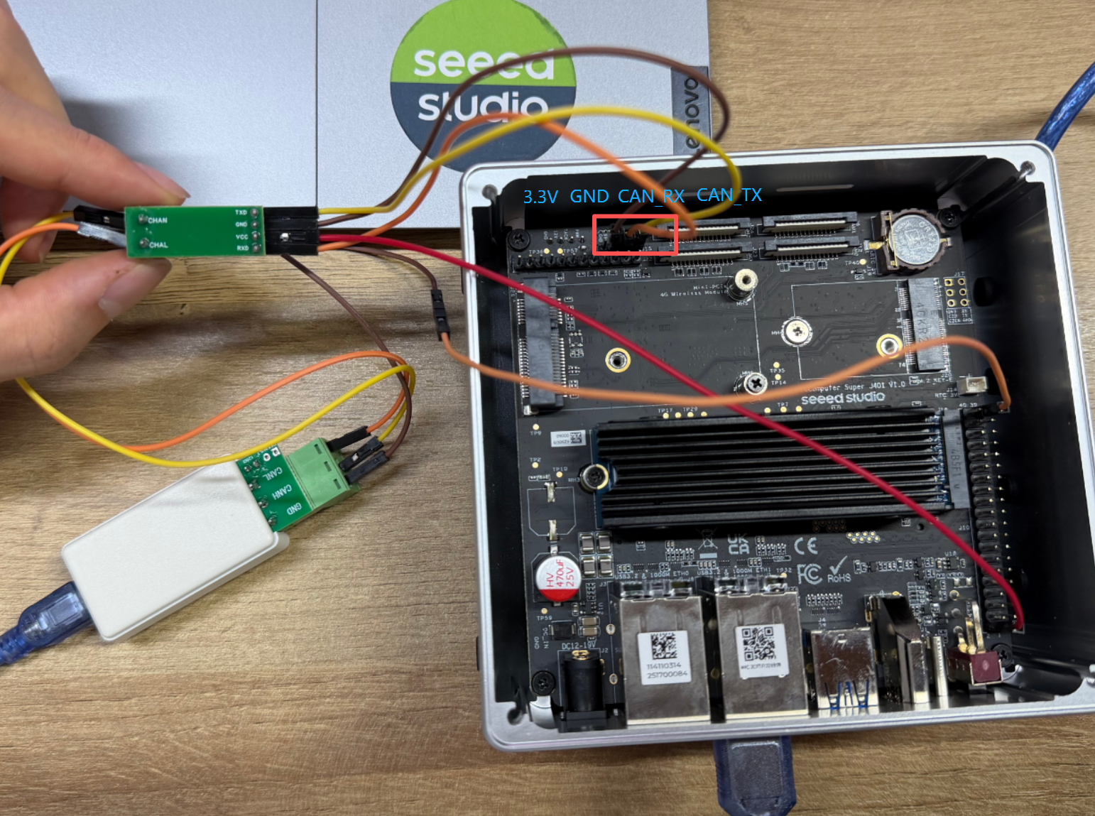
CAN
The reComputer Super series provides a CAN interface where the CAN signal is output directly from the SOM at TTL/CMOS levels, which is a non-standard differential signal requiring an external CAN transceiver to connect to a standard CAN bus; it supports CAN FD frame formats, allowing extended data length and higher data rates, making it suitable for industrial automation, robotics, automotive prototyping, and other applications requiring reliable, real-time communication.
Hardware Connection
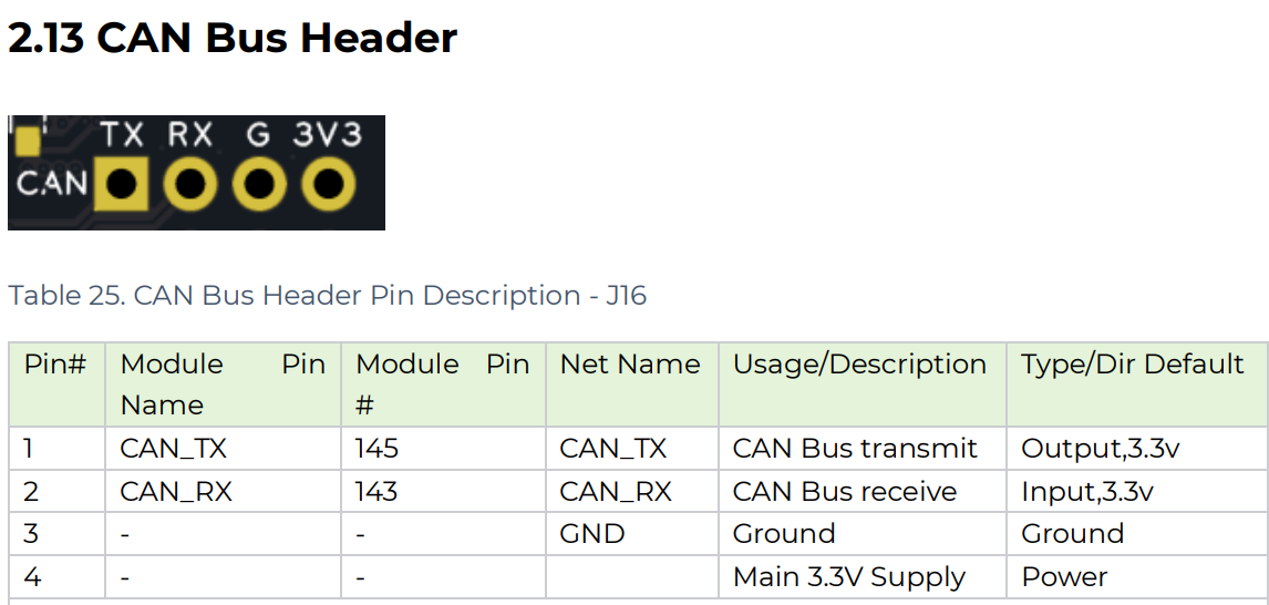
Please note the sequence of the connected lines (R OUT ↔ RX, D IN ↔ TX), and then convert them to CAN_L and CAN_H through the CAN bus transceiver.

According to the Datasheet of reComputer Super, connect the CAN heater to the CAN bus transceiver in the corresponding manner, then connect the CAN bus transceiver to the USB to CAN Analyzer Adapter, and finally connect it to the Jetson for loopback communication testing.
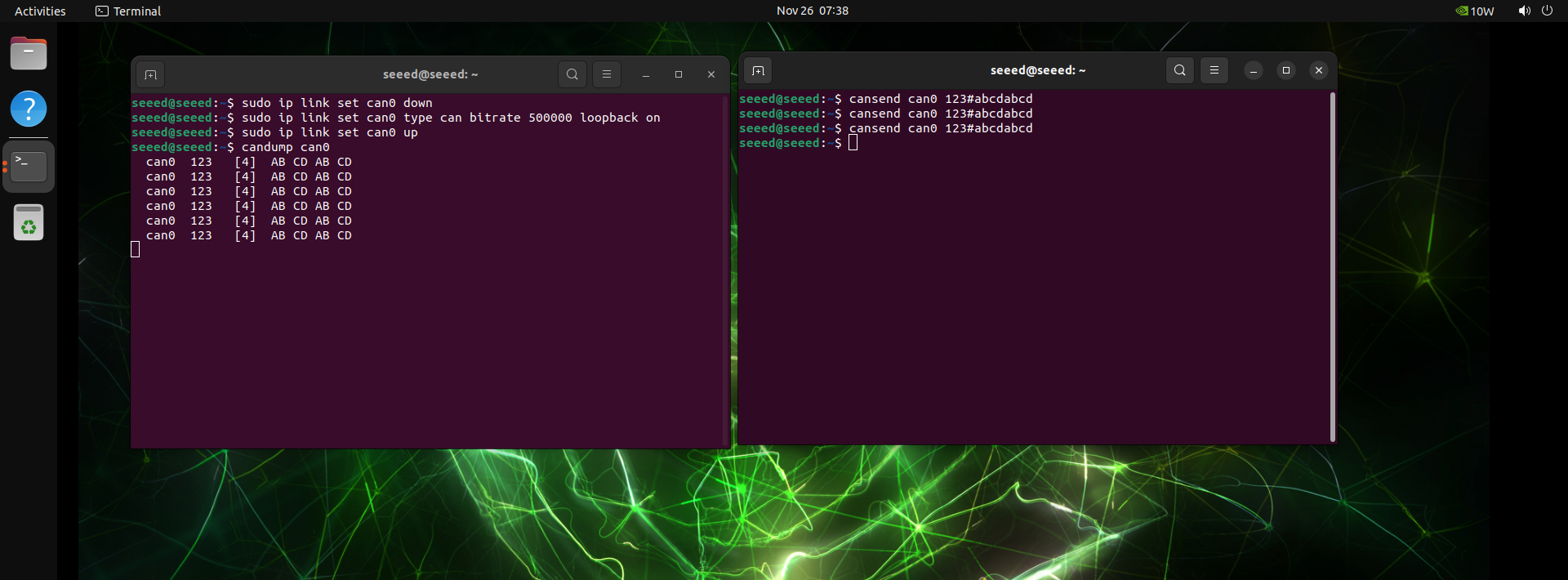
Usage Instruction
Step 1. Configure and open can0:
sudo ip link set can0 down
sudo ip link set can0 type can bitrate 500000
sudo ip link set can0 up
Step 2. Communication test. Open a terminal to receive signals.
candump can0
Step 3. Open another terminal to send the signal.
cansend can0 123#abcdabcd
Extension Port
The Extension Port includes a 40-pin extension header and a 12-pin control and UART header, providing versatile connectivity options for peripherals and communication interfaces.
40-Pin Extension Header

The 40-Pin Extension Header is a versatile expansion interface that provides various functions such as GPIO, I2C, SPI, and UART, making it convenient for connecting sensors, peripherals, or other modules.
The detail of 40-pin header is shown below:
| Header Pin | Signal | BGA Pin | Default Function |
|---|---|---|---|
| 1 | 3.3V | - | Main 3.3V Supply |
| 2 | 5V | - | Main 5V Supply |
| 3 | I2C1_SDA | PDD.02 | I2C #1 Data |
| 4 | 5V | - | Main 5V Supply |
| 5 | I2C1_SCL | PDD.01 | I2C #1 Clock |
| 6 | GND | - | Ground |
| 7 | GPIO09 | PAC.06 | General Purpose I/O |
| 8 | UART1_TXD | PR.02 | UART #1 Transmit |
| 9 | GND | - | Ground |
| 10 | UART1_RXD | PR.03 | UART #1 Receive |
| 11 | UART1_RTS | PR.04 | UART #1 Request to Send |
| 12 | I2S0_SCLK | PH.07 | Audio I2S #0 Clock |
| 13 | SPI1_SCK | PY.00 | SPI #1 Clock |
| 14 | GND | - | Ground |
| 15 | GPIO12 | PN.01 | General Purpose I/O |
| 16 | SPI1_CS1 | PY.04 | SPI #1 Chip Select #1 |
| 17 | 3.3V | - | Main 3.3V Supply |
| 18 | SPI1_CS0 | PY.03 | SPI #1 Chip Select #0 |
| 19 | SPI0_MOSI | PZ.05 | SPI #0 Master Out / Slave In |
| 20 | GND | - | Ground |
| 21 | SPI0_MISO | PZ.04 | SPI #0 Master In / Slave Out |
| 22 | SPI1_MISO | PY.01 | SPI #1 Master In / Slave Out |
| 23 | SPI0_SCK | PZ.03 | SPI #0 Clock |
| 24 | SPI0_CS0 | PZ.06 | SPI #0 Chip Select #0 |
| 25 | GND | - | Ground |
| 26 | SPI0_CS1 | PZ.07 | SPI #0 Chip Select #1 |
| 27 | ID_I2C_SDA (I2C0_SDA) | PDD.00 | I2C #0 Data |
| 28 | ID_I2C_SCL (I2C0_SCL) | PCC.07 | I2C #0 Clock |
| 29 | GPIO01 | PQ.05 | General Purpose I/O |
| 30 | GND | - | Ground |
| 31 | GPIO11 | PQ.06 | General Purpose I/O |
| 32 | GPIO07 | PG.06 | General Purpose I/O |
| 33 | GPIO13 | PG.00 | System Reserved |
| 34 | GND | - | Ground |
| 35 | I2S0_LRCK (I2S0_FS) | PI.02 | Audio I2S #0 Frame Sync |
| 36 | UART1_CTS | PR.05 | UART #1 Clear to Send |
| 37 | SPI1_MOSI | PY.02 | SPI #1 Master Out / Slave In |
| 38 | I2S0_SDIN (I2S0_DIN) | PI.01 | Audio I2S #0 Data In |
| 39 | GND | - | Ground |
| 40 | I2S0_SDOUT (I2S0_DOUT) | PI.00 | Audio I2S #0 Data Out |
Usage Instruction
Simple GPIO control example
#install
sudo apt-get install gpiod

# Search for the corresponding number for the pin
sudo gpiofind PH.00
gpiochip0 43

#Set the pin to H, then press Enter to release.
sudo gpioset --mode=wait 0 43=1

#Set the Pin to L, then press Enter to release.
sudo gpioset --mode=wait 0 43=0

#gpio 0_119 Low level maintained for 2 seconds
sudo gpioset --mode=time -s 2 0 119=0

#input
sudo gpioget 0 43
If you want to configure the GPIO that is not enabled by default, please refer to the following steps:
Enable 40-Pin Header:
sudo /opt/nvidia/jetson-io/jetson-io.py


Save and reboot.
Configure the uncontrolled GPIO through the Overlay configuration:
Step 1. Download and extract the overlay package to your jetson device.
wget https://files.seeedstudio.com/wiki/overlay.zip
Step 2. Copy build.sh and gpio-overlay.dts to Jetson.
Step 3. Edit the pio-overlay.dts file and modify it to include the pinmux definitions for the pins you need.
more details you can see in jetson-orin-nx-and-orin-nano-series-pinmux-config
Step 3. Enable overlay configuration.
sudo bash ./build.sh
#The following command needs to be executed only once.
sudo /opt/nvidia/jetson-io/config-by-hardware.py -n "seeed gpio config Overlay"
Step 4. Reboot the device enables the configuration to take effect.
sudo reboot
Step 5. Now you can control the pins by gpioset that were just modified.
#For example px7
sudo gpioset --mode=wait 0 121=1
12-Pin Control and UART Header

The 12-Pin Control and UART Header provides essential control signals and UART communication interfaces for connecting and managing external devices.
The pin functions of reComputer Super are similar to those of reComputer Classic. For more detailed information, please refer to here.
HDMI
reComputer Super is equipped with an HDMI 2.1 Type A port, which supports a resolution of 7680x4320. This allows for ultra-high-definition video output.
Resources
- User Manual&Datasheet
- Temperature Test Report
- Schematic
- 3D File
- Mechanical Document-reComputer Super
- Mechanical Document-reComputer Super PCBA
Tech Support & Product Discussion
Thank you for choosing our products! We are here to provide you with different support to ensure that your experience with our products is as smooth as possible. We offer several communication channels to cater to different preferences and needs.