reComputer Mini J501 WiFi Module Installation
Introduction
In this document, you will learn how to disassemble the reComputer Mini J501 and install or replace a Wi-Fi module (M.2 Key E).
The Wi-Fi slot is on the underside of the reComputer Mini J501 Carrier Board. The rear expansion board covers the M.2 Key E slot and must be detached for Wi-Fi service. The top expansion board has cutouts that expose the carrier board mounting screws, so it does not need to be removed during service. The same disassembly steps through carrier board removal also apply when replacing the NVMe SSD (M.2 Key M) — the rear expansion board does not cover that slot.
Power off the device and disconnect all cables (including DC input and Ethernet) before disassembly. Use ESD-safe handling when touching the carrier board and M.2 modules.
reComputer Mini (J501)
The reComputer Mini J501 uses the Robotics J501 Mini carrier board with NVIDIA Jetson AGX Orin modules (32GB/64GB), delivering up to 275 TOPS AI performance in a compact industrial enclosure. The carrier board provides dual Ethernet, USB 3.2, DisplayPort, and M.2 expansion slots including M.2 Key E for Wi‑Fi/BT.
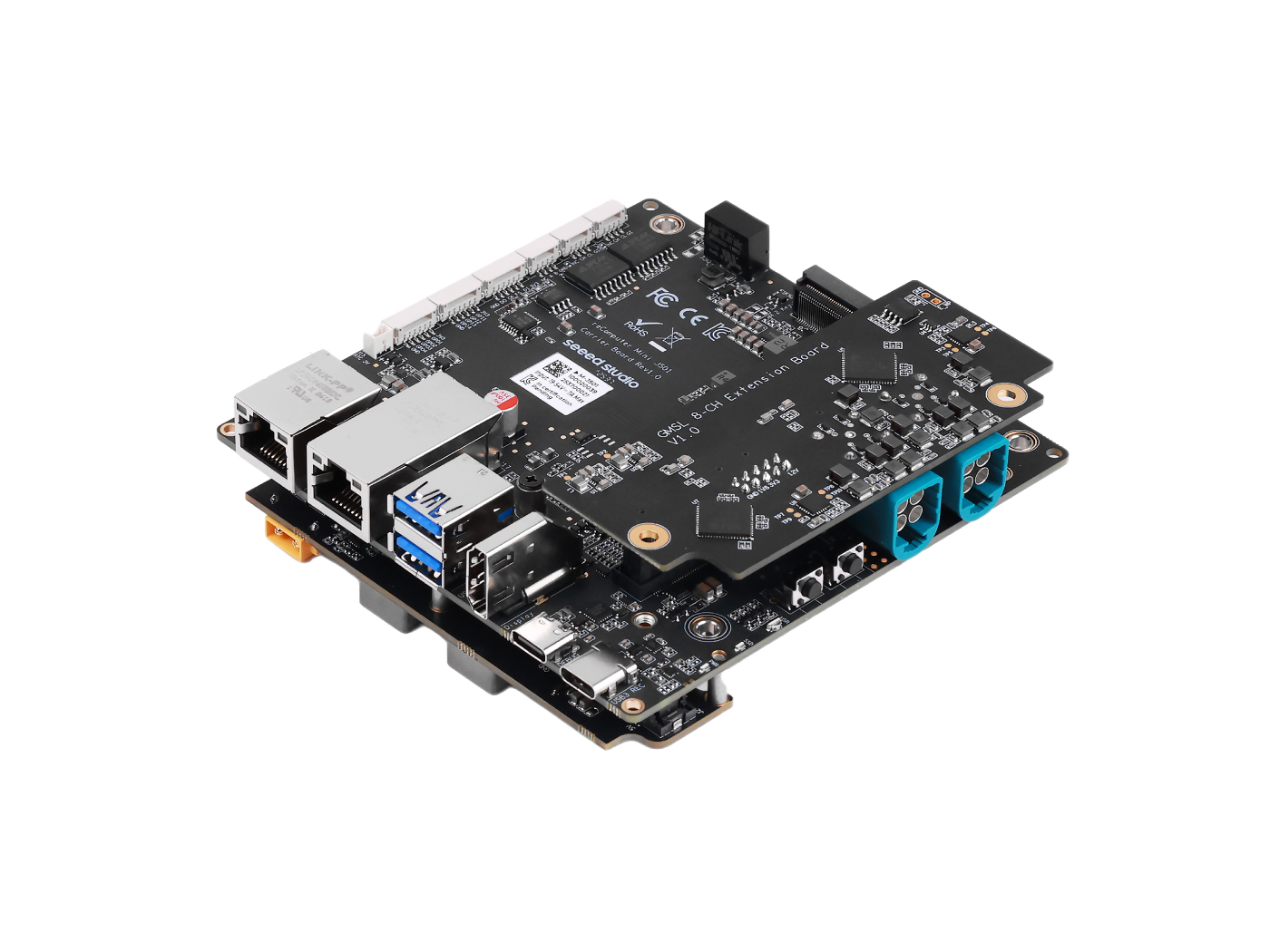
For device specifications, JetPack flashing, and interface usage, see Robotics J501 Mini carrier board Hardware and Getting Started.
Wi-Fi Module
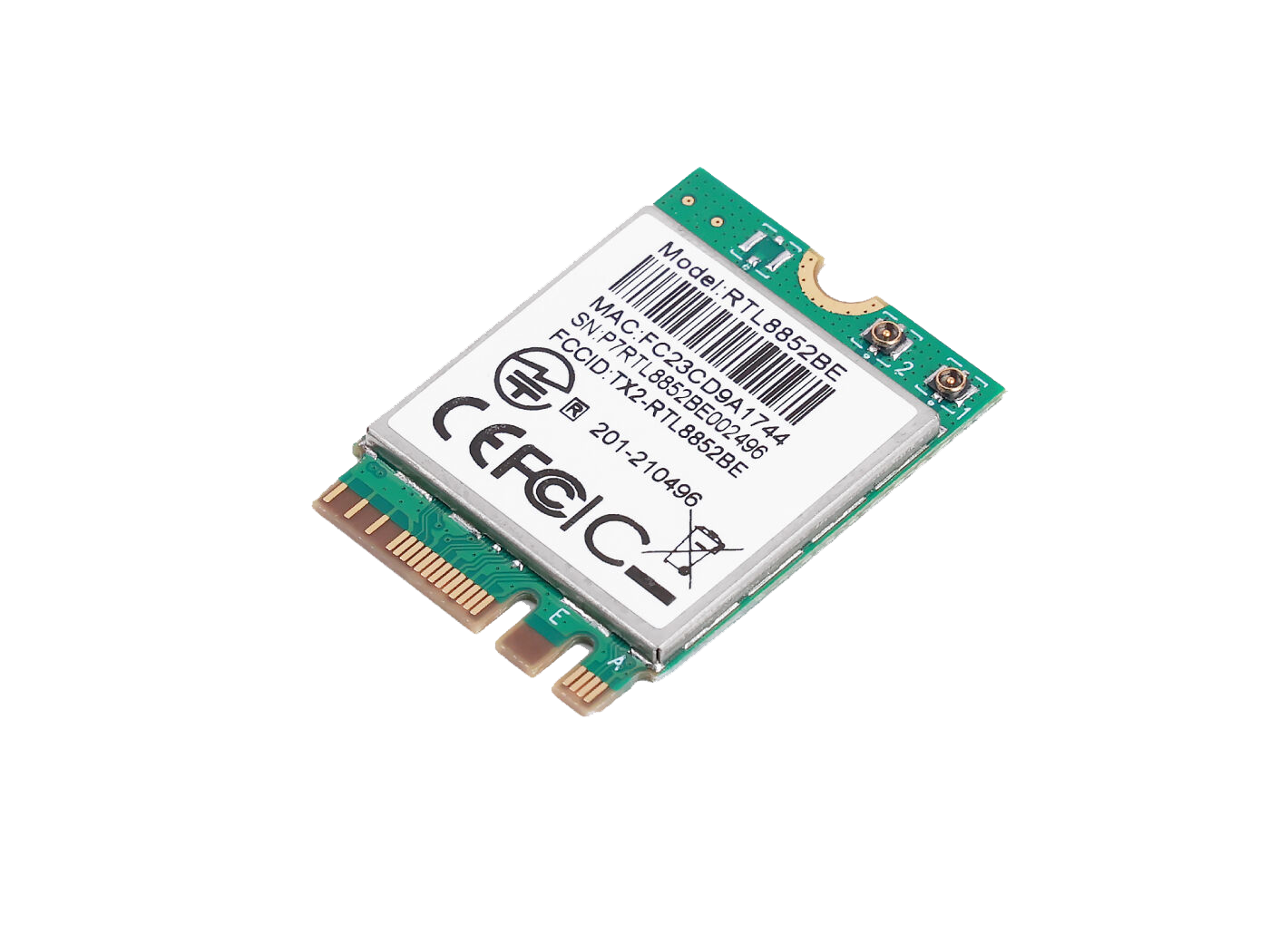
We recommend using a Realtek M.2 Key E Wi‑Fi/BT module that is compatible with Jetson (for example RTL8852BE).
Hardware Connection
This guide focuses on Wi-Fi module installation. To replace the NVMe SSD, follow Steps 2–3 only — skip Step 4 (rear expansion board removal).
Step 1. Prepare all materials that will be used.
- reComputer Mini J501 enclosure (powered off)
- Compatible M.2 Key E Wi-Fi/BT module
- IPEX antenna cable(s) (usually included with the Wi-Fi module)
- Phillips screwdriver
Disassemble the J501 Enclosure
Step 2. Remove the top enclosure cover.

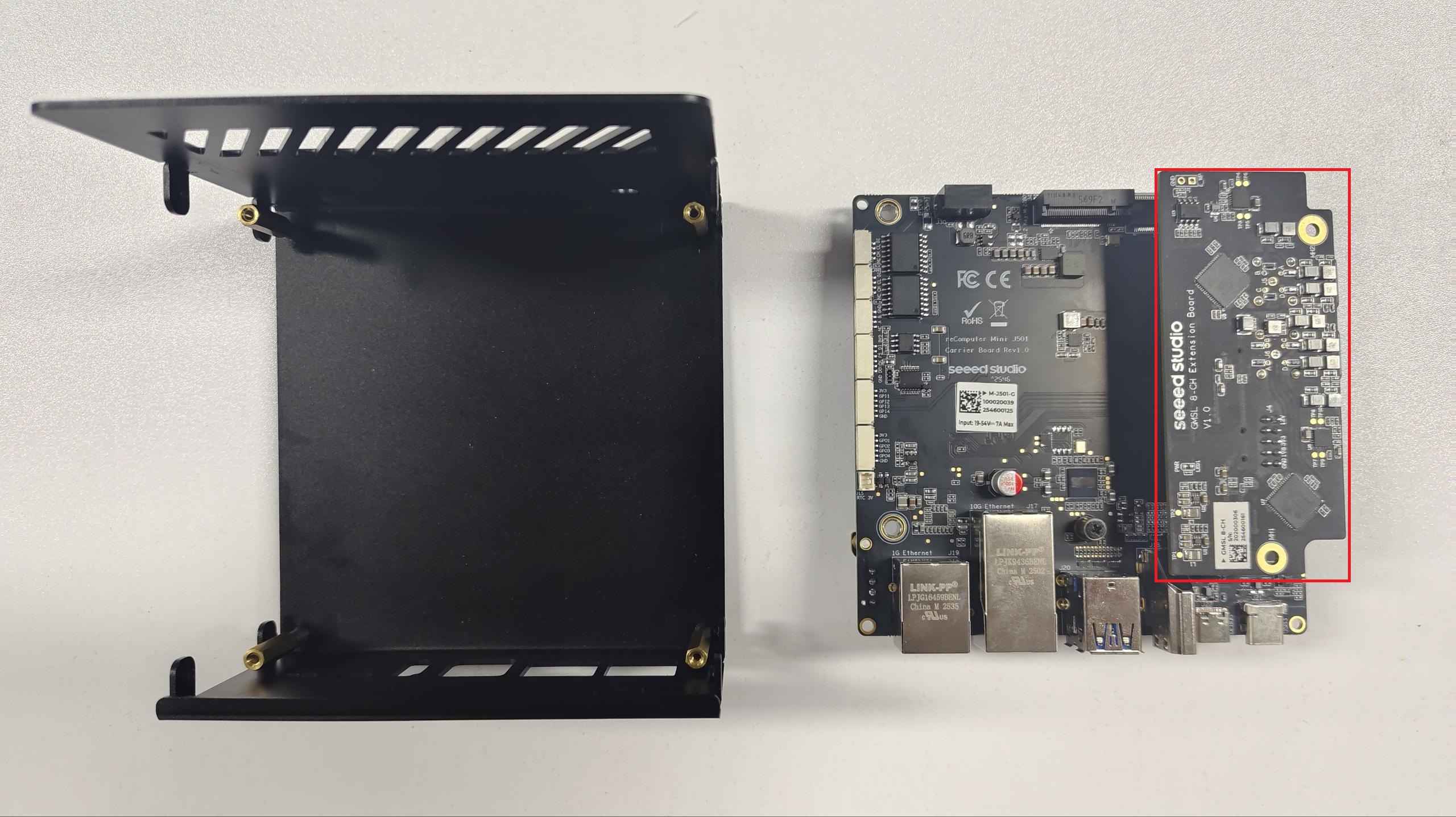
Step 3. Remove the main carrier board.
Remove all four corner mounting screws on the carrier board (marked in red below).
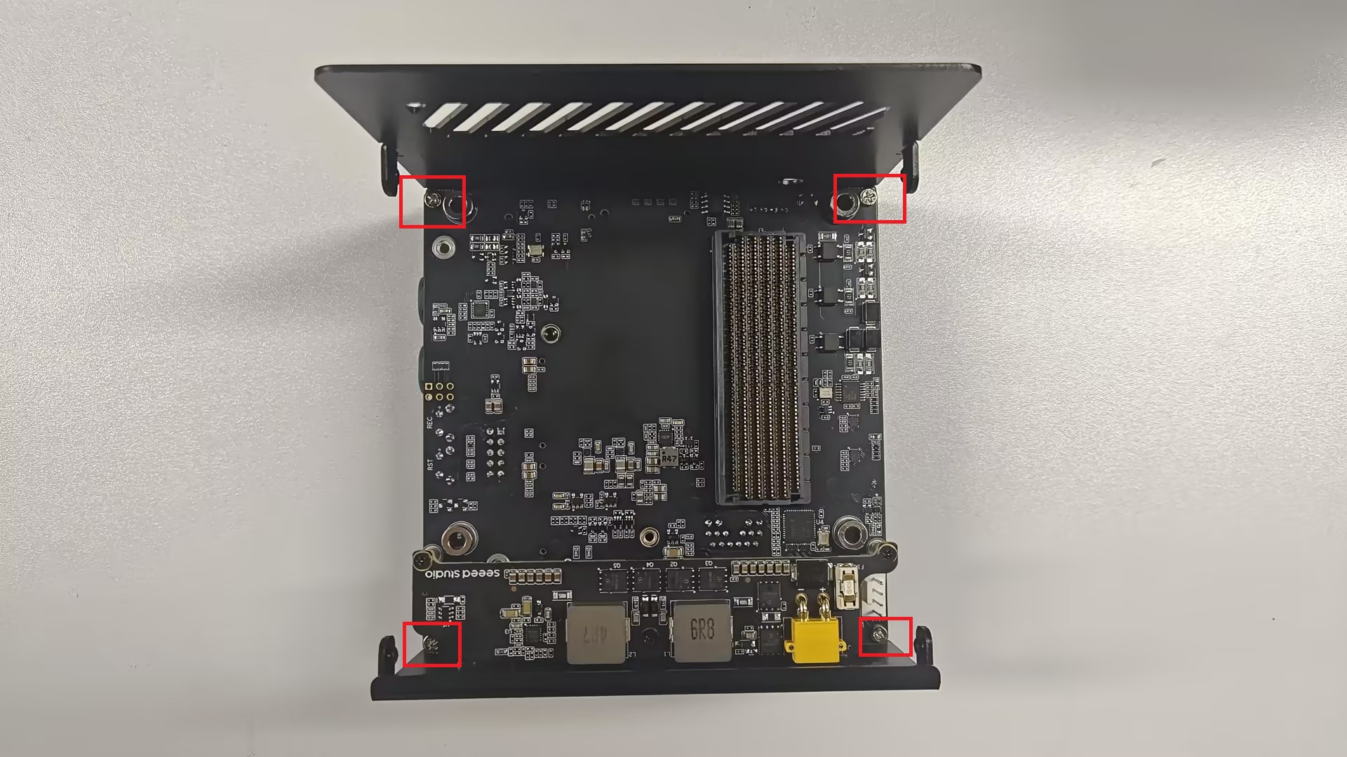
- Carefully lift the carrier board up and out of the chassis.
- Place the board on a clean, non-conductive surface.
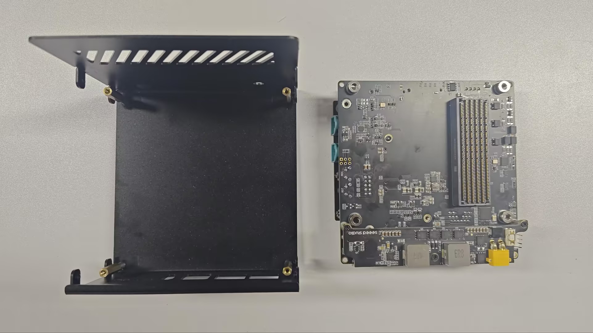
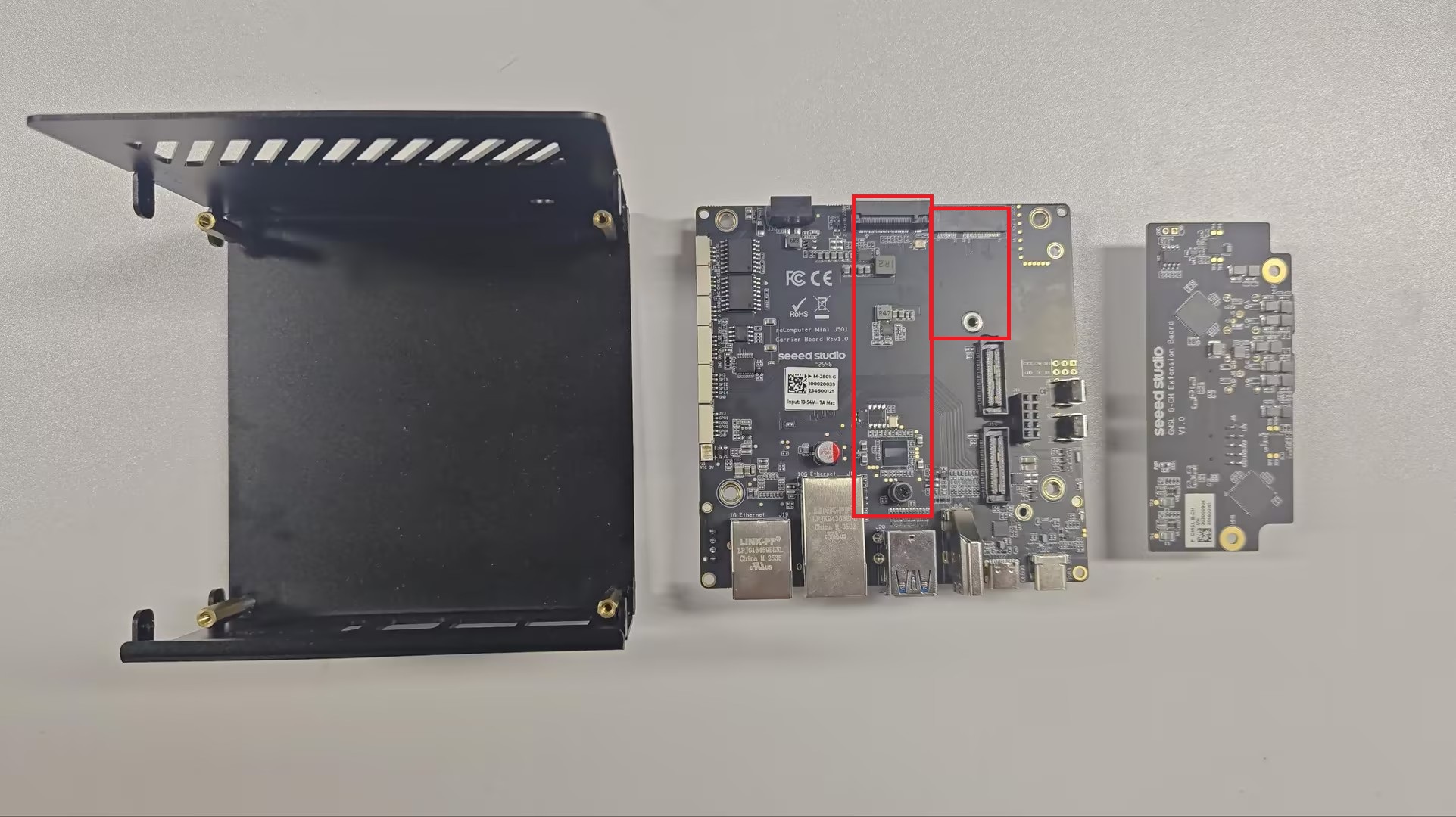
Step 4. Remove the rear expansion board (Wi-Fi installation only).
Flip the carrier board over so the bottom side faces up. A rear expansion board is attached to the back via board-to-board connectors and blocks access to the M.2 Key E slot. Skip this step if you are only replacing the NVMe SSD in the M.2 Key M slot.
- Gently pull the rear expansion board away from the carrier board connectors.
- Set the rear expansion board aside.
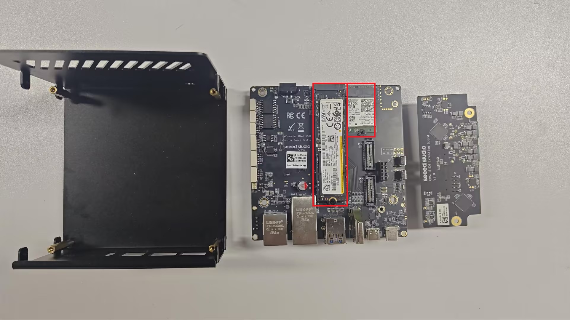
The M.2 Key E (WiFi/BT) slot is now accessible. The steps below cover Wi-Fi module installation.
Install the Wi-Fi Module
Step 5. Insert the wireless module into the M.2 Key E port at the correct angle (typically 30°), then press down and secure with the mounting screw.
Step 6. Connect the IPEX antenna cable(s) to the module. Route the cables clear of metal shields and screw holes so they are not pinched during reassembly.
Reassemble the J501 Enclosure
Step 7. Reassemble the device in reverse order:
- If you removed it, reattach the rear expansion board to the back of the carrier board.
- Place the carrier board back into the chassis and tighten the four corner screws.
- Replace the top enclosure cover.
Software Setup (Driver Installation)
If you are using an RTL8852BE module, follow:
Tech Support & Product Discussion
Thank you for choosing our products! We are here to provide you with different support to ensure that your experience with our products is as smooth as possible. We offer several communication channels to cater to different preferences and needs.