reComputer R1000 Assembly Guide

reComputer R1000 supports multiple IoT wireless communication including 4G, LoRa®, Wi-Fi/BLE, and Zigbee. It allows expansion of SSD cards via M.2 socket for increased storage or NPU accelerator for AI capabilities. Moreover, our hardware engineering services include logo customization, package branding, labeling, firmware flashing, imaging service, and more, providing comprehensive support for your specific needs.
This Wiki will show you how to Assemble and Disassemble the unit to install peripherals components, as well as the option for mounting
Hardware prerequisite
You need to prepare the following hardware
- reComputer R1000 x 1
- Accessories
- Screw Driver set
- Phillips + 3.5 bit
- Phillips + 3.0 bit
- Slotted - 2.5 bit
Disassembly Guide
Following these steps should help you disassemble the device without any issues.

STEP 1: Remove the Four Screws at the Bottom and Grounding Screw from Side Panels:
- Locate and unscrew the four screws located at the bottom of the device using an appropriate screwdriver.
- Remove and unscrew the grounding screw from the side panels.
STEP 2: Take Off the Floor Panel:
- Once the screws are removed, carefully lift off the floor panel from the device.
STEP 3: Remove the Plastic Side Panels:
- Identify the plastic side panels on three sides of the device.
- Gently pry or unsnap each side panel from the device. If they are tight, you may need to use tools, but be careful not to damage the panels.
STEP 4: Be Mindful of the Boot Switch Plastic Plate:
- Note the boot switch on one of the panels; it may have a small plastic plate attached.
- Ensure this plate doesn't fall off or get lost during the disassembly process.
STEP 5: Take Down the Aluminum Outer Casing:
- Once the side panels are removed, you can access the aluminum outer casing.
- Carefully lift and remove the aluminum casing from the device.
STEP 6: Remove the four screws that secure the PCB in place

Assemble SSD
STEP 1: Remove the back cover following the disassembly guide.
STEP 2: Load the SSD into the M.2 socket and lock the screws.
Assemble Wi-Fi/BLE Antenna

STEP 1: Disassemble the entire device following section Disassembly Guide.
STEP 2: Connect the feeder line from the CM4 module to antenna hole following the illustrastions below.
STEP 3: Assemble the device for usage.
Install LTE and GNSS Antenna
Assemble 4G/LoRa®/Zigbee Module and Antenna

STEP 1: Make sure the module for Mini-PCIe slots is loaded above the SSD card.
STEP 2: Load the 4G module/LoRa® Module/Zigbee Module(following the matching relationship of each slot according to section"2.2.8") into the Mini-PCIe slot and lock the screws.
STEP 3: Install the feeder line following the pictures below.

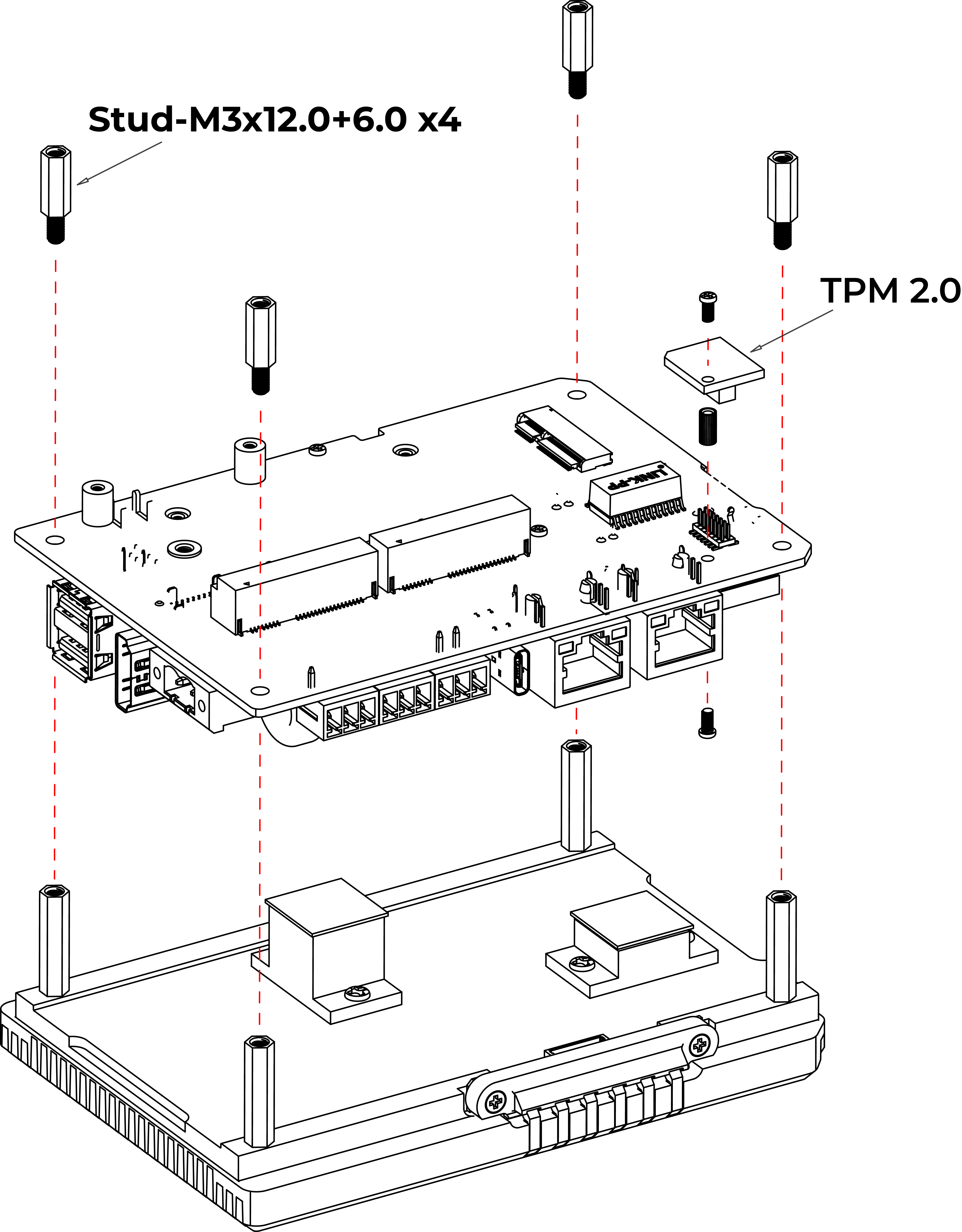
Assemble TPM 2.0 Module
STEP 1: Remove the back cover following the disassembly guide.
STEP 2: Load the TPM 2.0 module into the J13 socket.
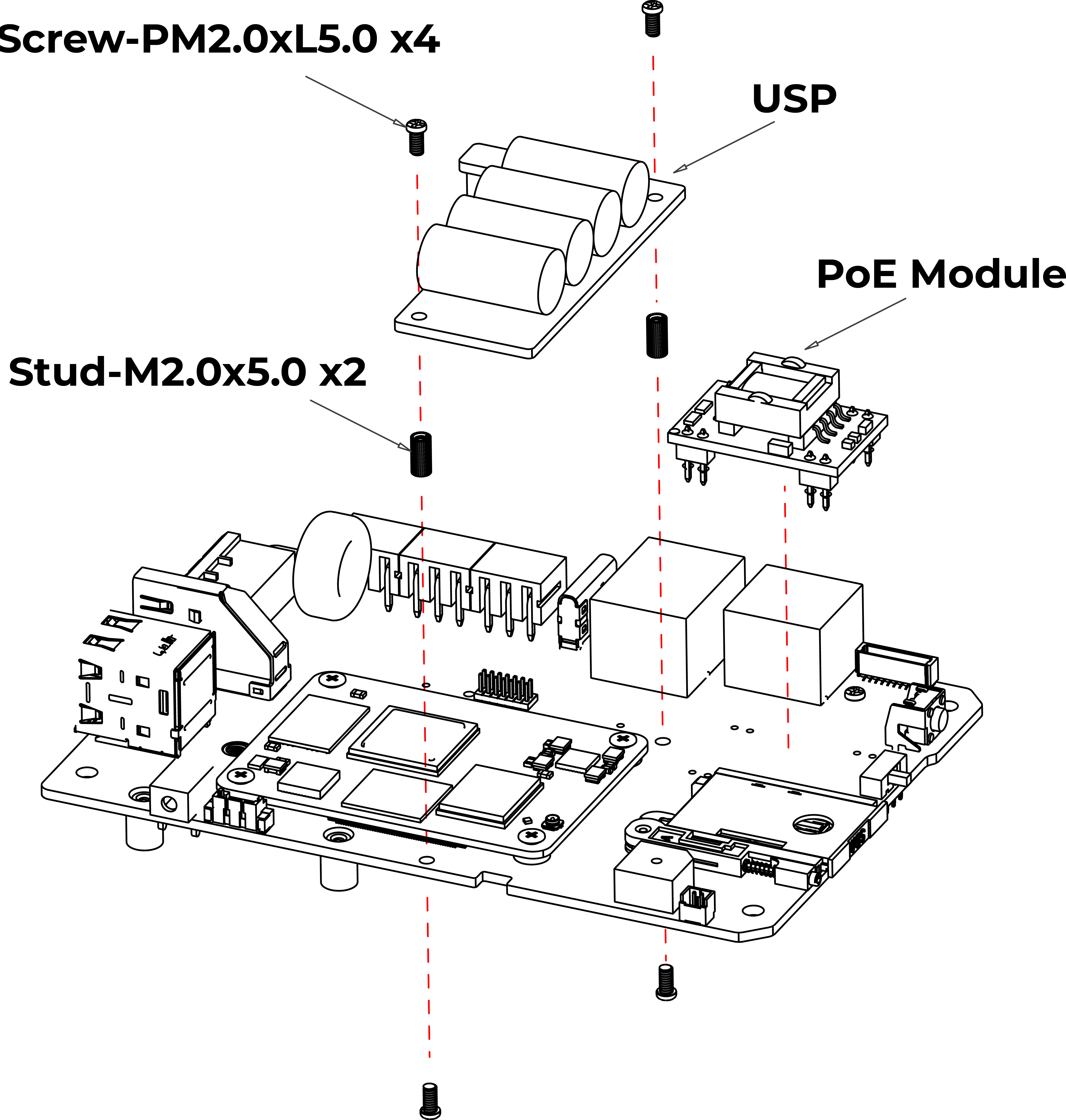
Assemble UPS and PoE module

STEP 1: Before installing the UPS and PoE module on the CM4 module side of board, disassemble the entire device following the disassembly guide provided.
STEP 2:
- Using two PM2.0xL5.0 screws and M2.0x5.0 standoffs, secure the UPS module onto two holes without metal contact pads.
- Make sure the UPS module is aligned properly and firmly attached using the provided screws and standoffs.
STEP 3: Install the PoE Module
- Align the PoE module with the designated aperture on the board.
- Carefully solder the PoE module onto the board. Due to the compact nature of the board, exercise caution while soldering to avoid damaging nearby components.
Please correctly install the PoE module, placing the white dots facing inward, next to a capacitor.
Mounting Guide
DIN-rail Mounting Guide
reComputer R1000 offers various installation methods. The DIN-rail clip and installation screws are included in the packaging. Follow the diagram to correctly attach the DIN-rail clip to the mounting holes on the side of the device. Once the screws are securely fastened, you can then install the device onto the mounting rail.
STEP 1: Place the device and rail clip on the upper edge of the standard profile rail at the position shown and push the device down. STEP 2: Swing the rail clip of the device from below through the standard profile rail. STEP 3: Push the device in the direction of the standard profile rail. You will hear the device click into place.
Removing STEP 1: Push down the device until it is released by the rail clip. STEP 2: Swing the device out of the standard profile rail. STEP 3: Lift the device up and off.
Wall Mounting Guide
Vertical mounting method is also suitable for reComputer R1000, however the mounting brackets are not included in box, that need additional purchase.
STEP 1: Lay the mounting brackets on the rear of the device. STEP 2: Fasten the brackets with supplied screws. STEP 3: Mark the bore holes, drill the required holes in the wall and fasten the device to the wall using two screws.
Accessories List


Tech Support & Product Discussion
Thank you for choosing our products! We are here to provide you with different support to ensure that your experience with our products is as smooth as possible. We offer several communication channels to cater to different preferences and needs.