How to use CODESYS to configure the Modbus rtu function of R1000
Introduction
This article mainly introduces how to use the modbus rtu function of reComputer R1000 based on CODESYS. We will use the two rs485 ports of reComputer R1000, one port is used for Modbus master and the other port is used for Modbus slave. This article will detail how to configure Modbus master and Modbus slave on CODESYS and show how to deploy them on reComputer R1000.
Hardware Preparation
| reComputer R1000 |
|---|
 |
Software Preparation
Getting Start
Before you begin, please ensure that your reComputer R1000 is in the same network segment as the host and that you have deployed CODESYS run-time on the reComputer R1000. For information on how to deploy CODESYS run-time, please refer to wiki
Hardware Configuration
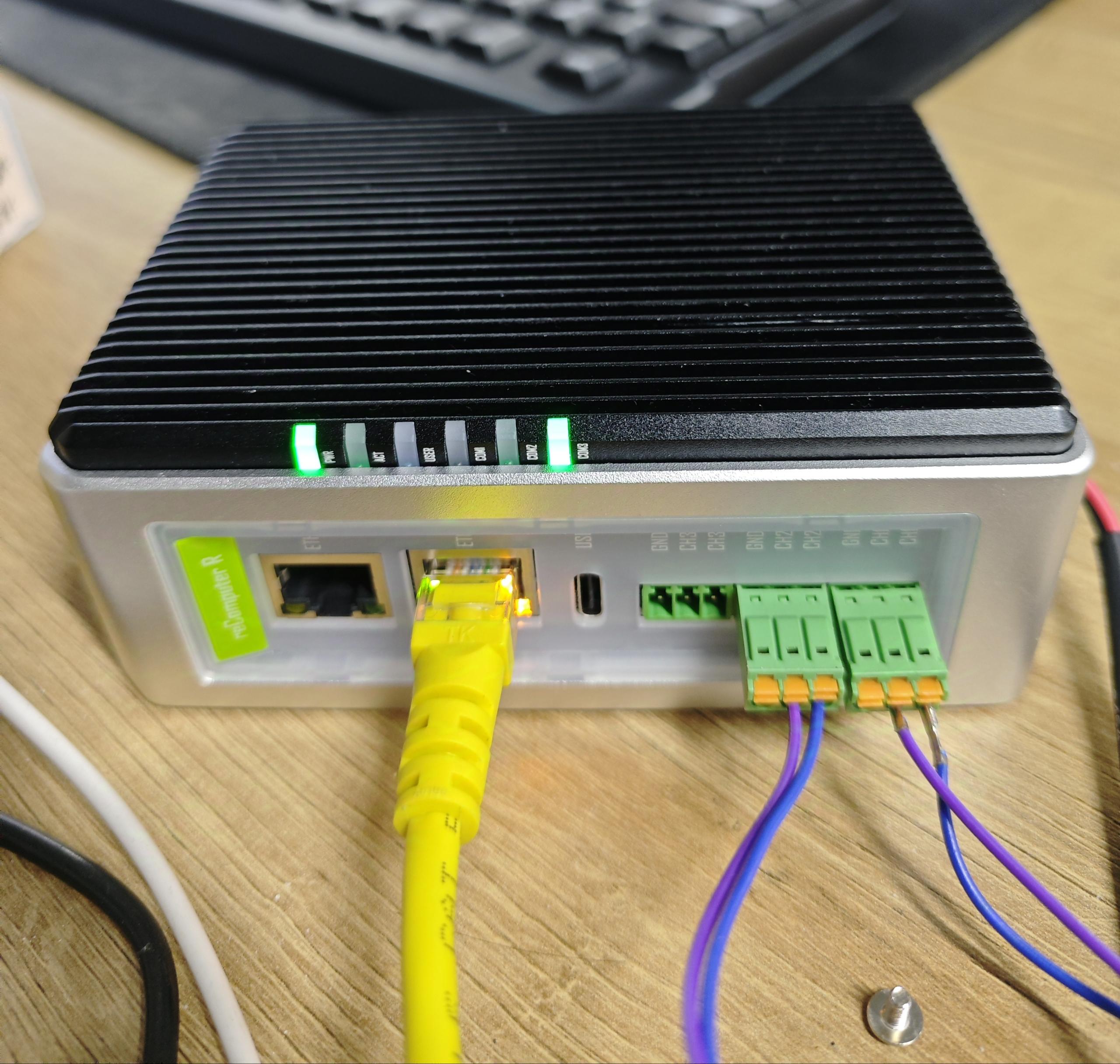
The two RS485 ports of R1000 are connected, one as Modbus master and the other as Modbus slave
Modify the configuration file of R1000
Enter the command:
sudo nano /etc/codesyscontrol/CODESYSControl.cfg
Add the following content:
# Add the following content to the end of the file, where ttyAMAx is the serial port number of reComputer R1000. Linux.Devicefile.1~3 represents the serial port number in CODESYS. Here, the serial port number of CODESYS is bound to the serial port number of reComputer R1000, otherwise CODESYS cannot identify the correct serial port
    [SysCom]
    Linux.Devicefile.1=/dev/ttyAMAx
    Linux.Devicefile.2=/dev/ttyAMAx
    Linux.Devicefile.3=/dev/ttyAMAx
Then enter the following command to restart the CODESYS service:
    sudo systemctl restart codesyscontrol.service
    sudo systemctl restart codesysedge.service
Modbus master configuration
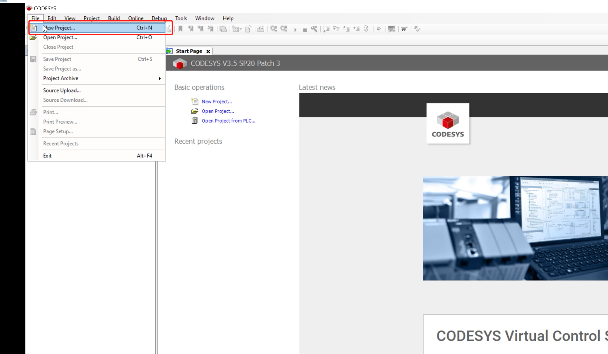
Step 1: Open CODESYS, click File--->NEW Project to create a new project
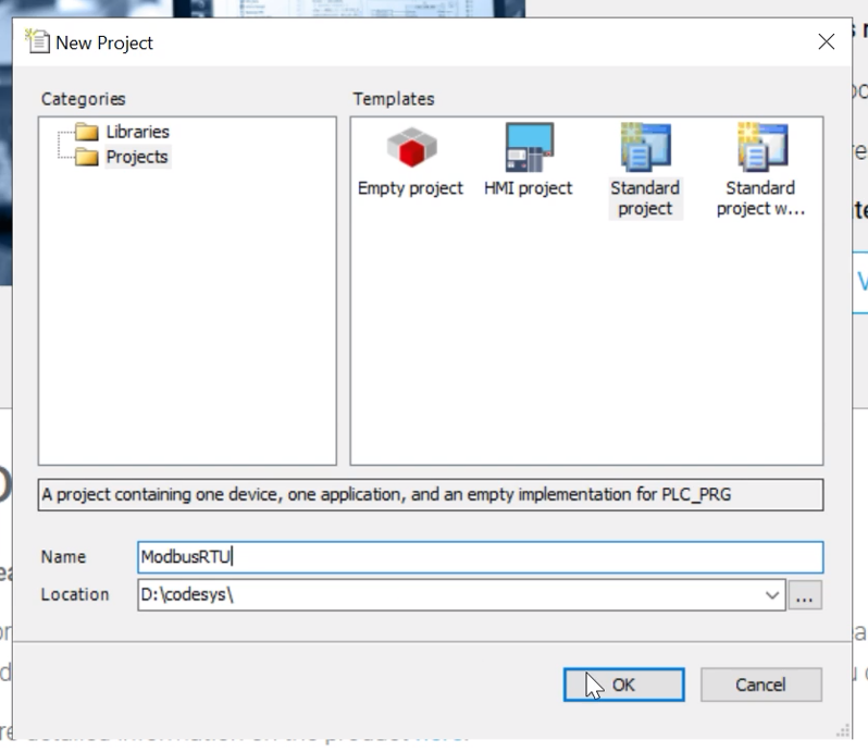
Step 2: Enter the project name, select Standard project, then click OK
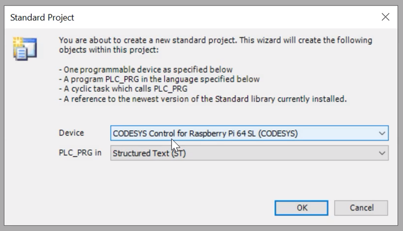
Step 3: Select CODESYS Control for Raspberry Pi 64 SL (CODESYS) in the Device column, select Structured Text (ST) in PLC_PRG in, and then click OK
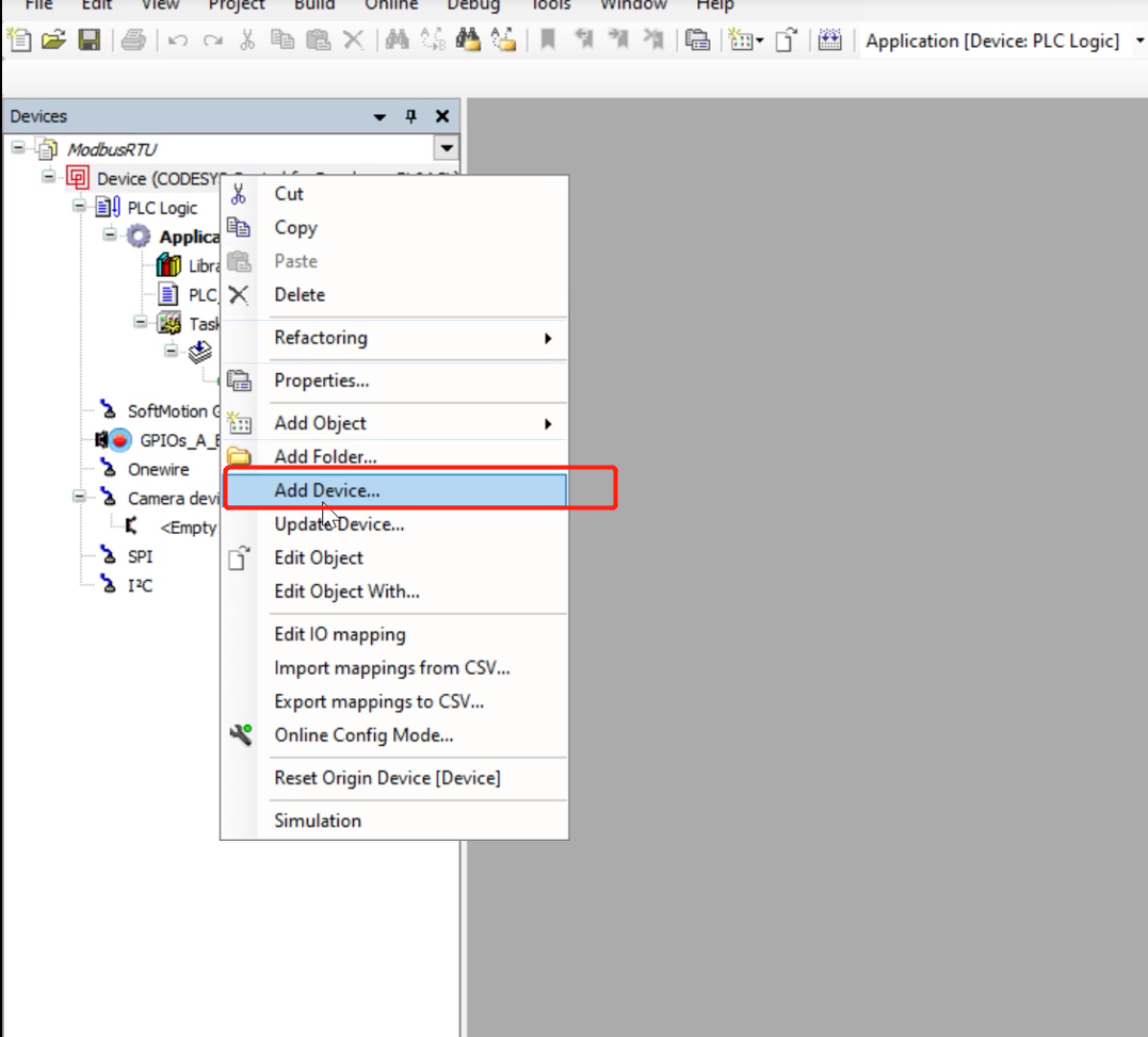
Step 4: Right click on the project and select Add Device to add the device
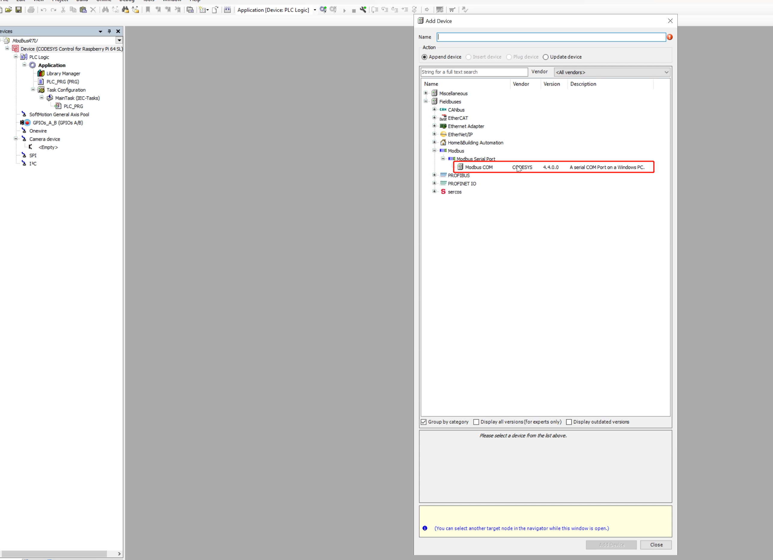
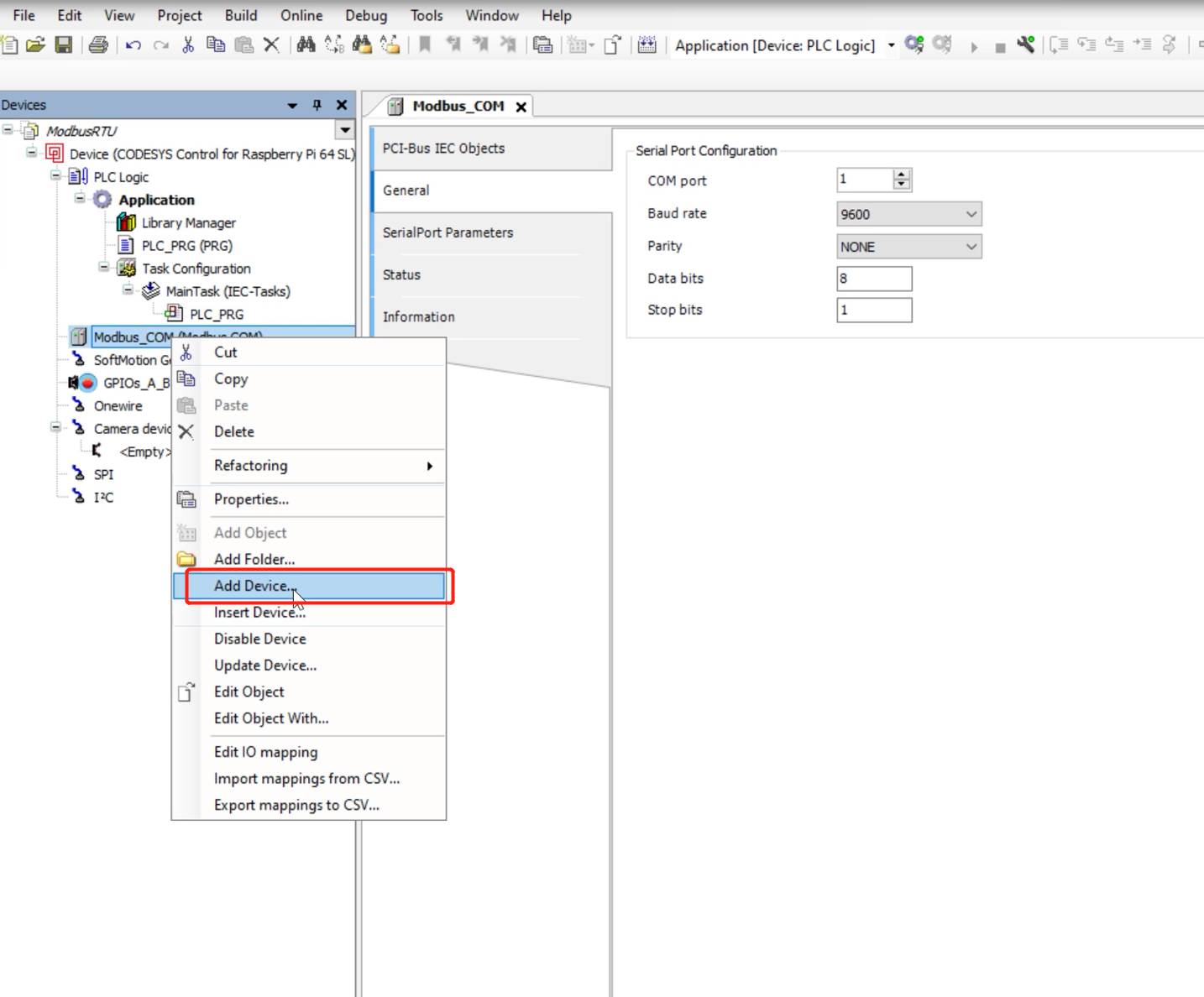
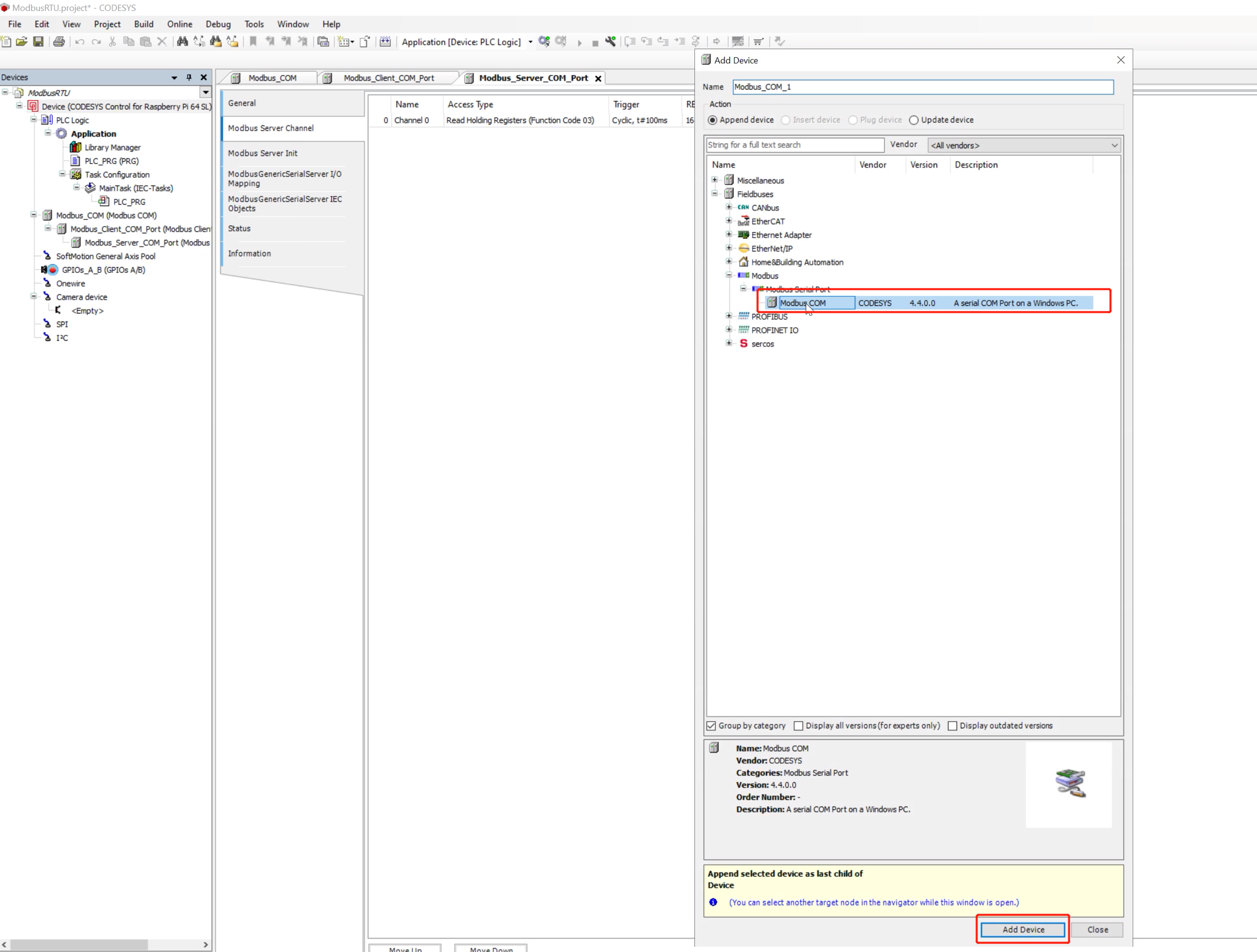
Step 5: Click Modbus--->Modbus serial Port--->Modbus COM to add a Modbus serial port device
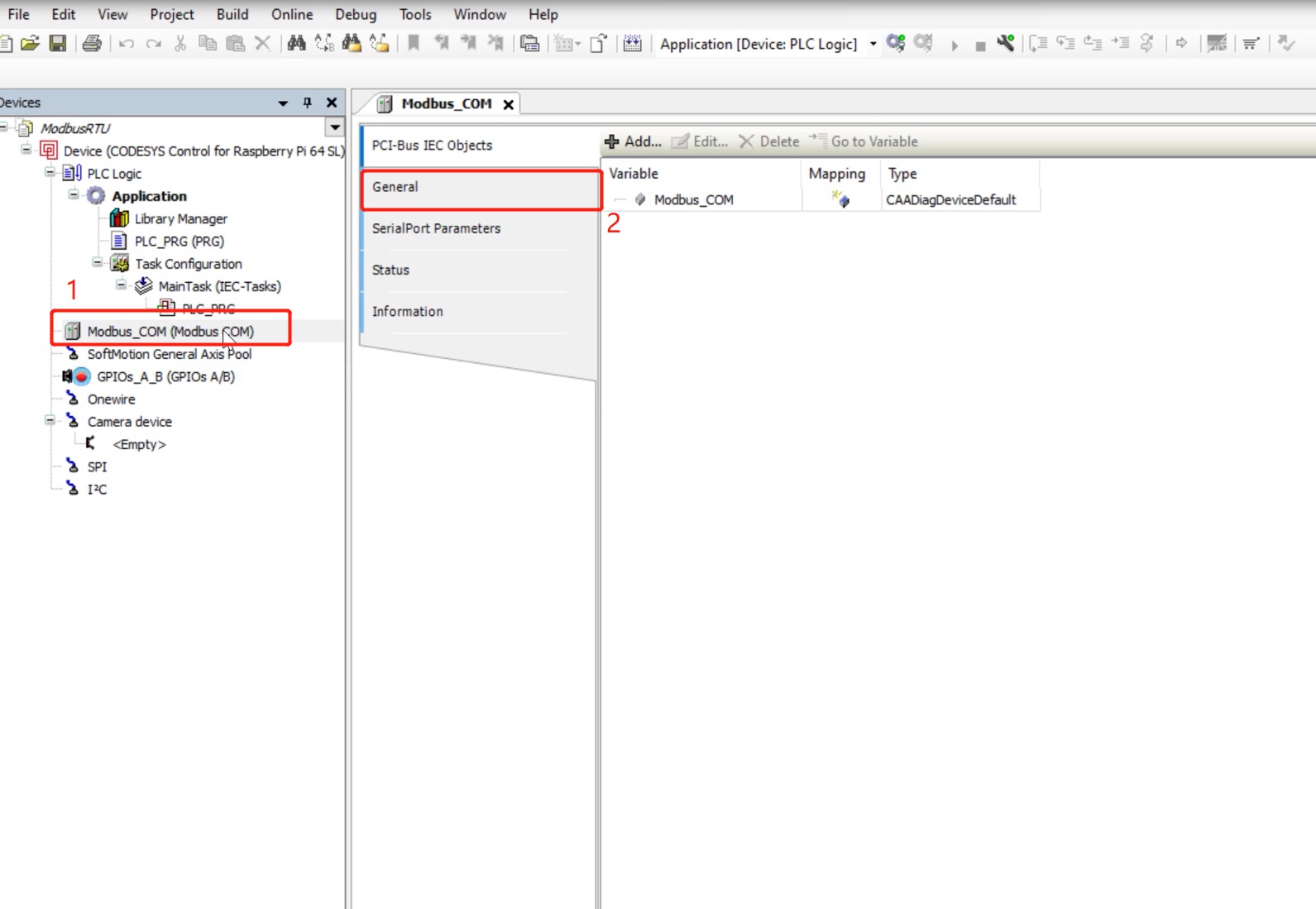
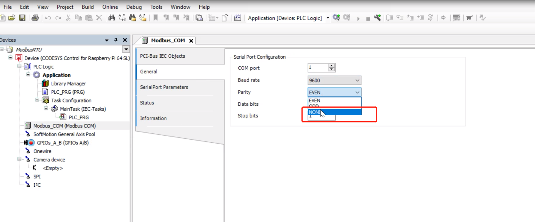
Step 6: Double-click the newly added Modbus_COM, click General, you can set the serial port number and baud rate and other information
Step 7: Right-click Modbus_COM and click Add Device to add a Modbus device to this port
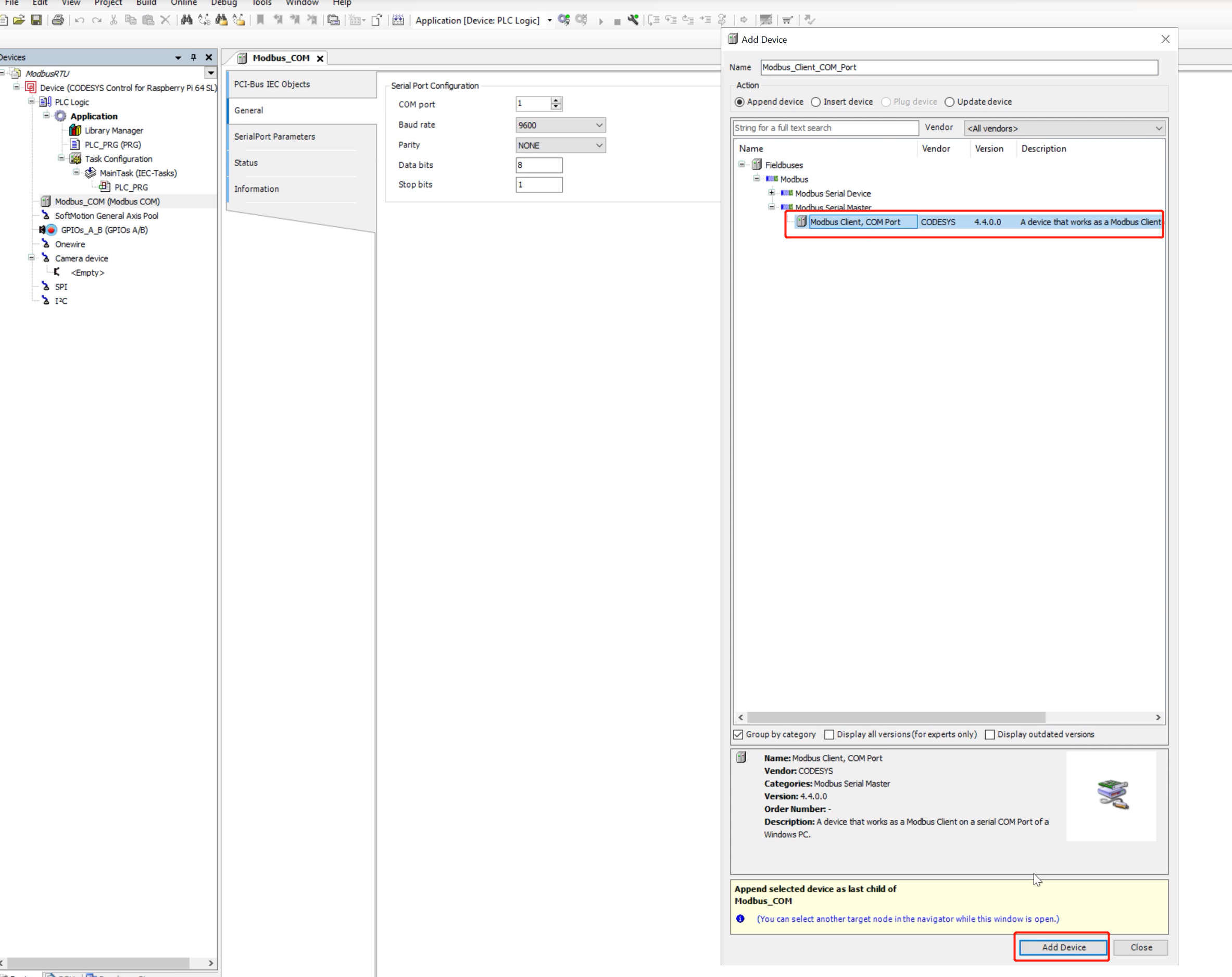
Step 8: Select Modbus Serial Master ---> Modbus Client, COM Port to bind a Modbus Master device to this serial port
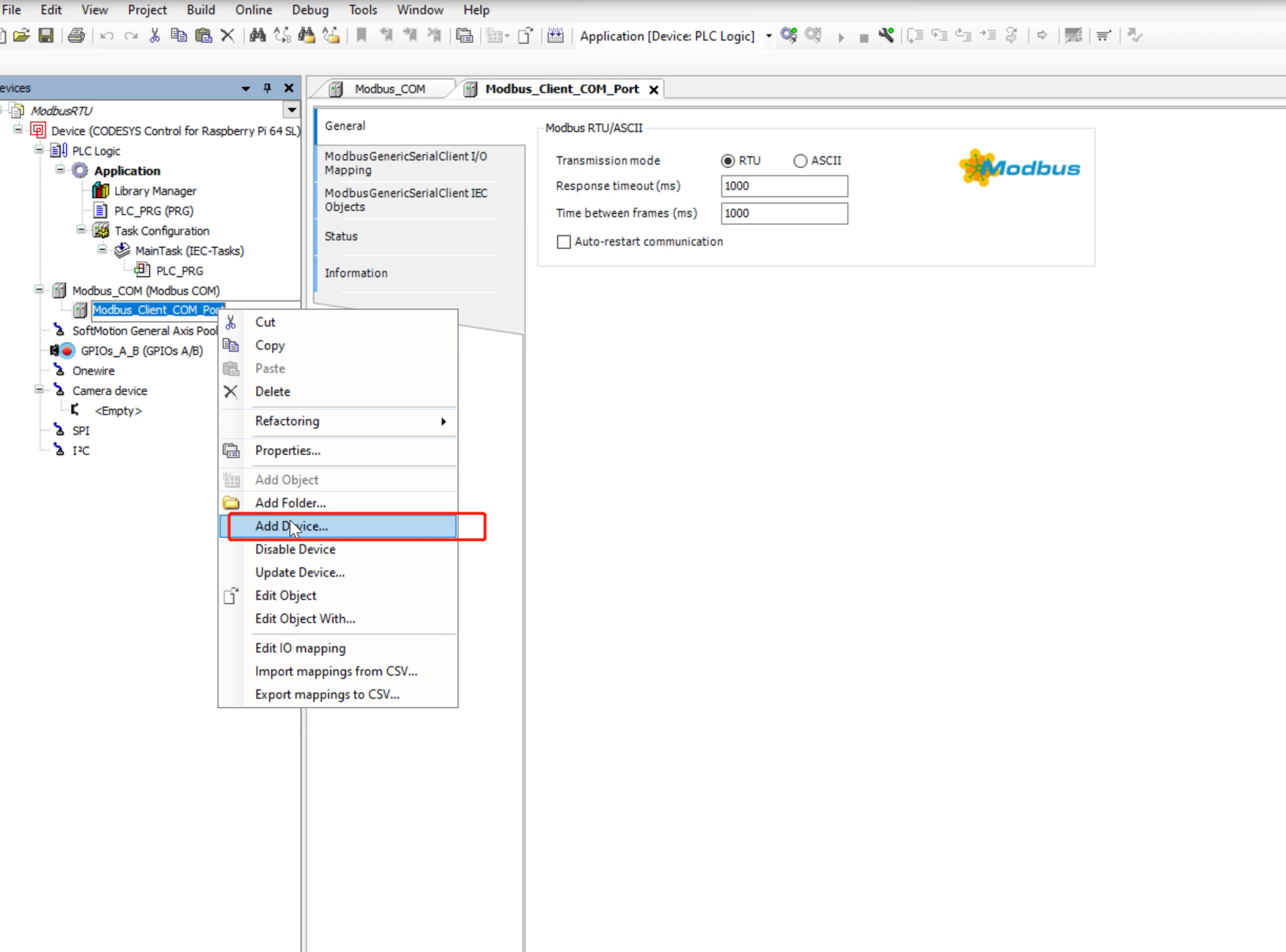
Step 9: Right-click Modbus_Clent_COM_Port and select Add Device to add the slave device to be operated for this Modbus Master. You can add multiple slave devices here. The slave devices here represent the slave devices that the master station wants to operate. You need to configure the operations that the master station will perform on these slaves later.
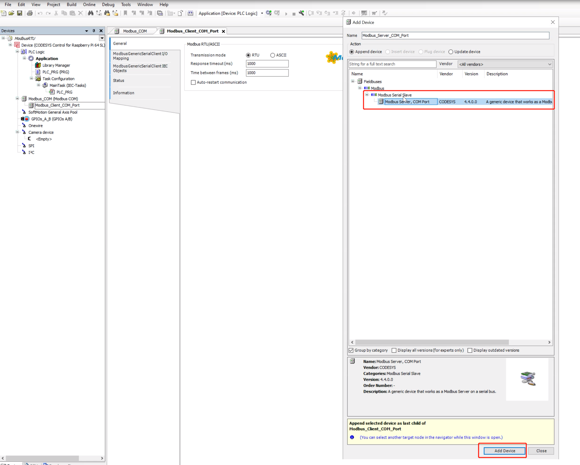
Step 10: Select Modbus Serial Slave ---> Modbus Server, COM Port to add a Modbus slave device
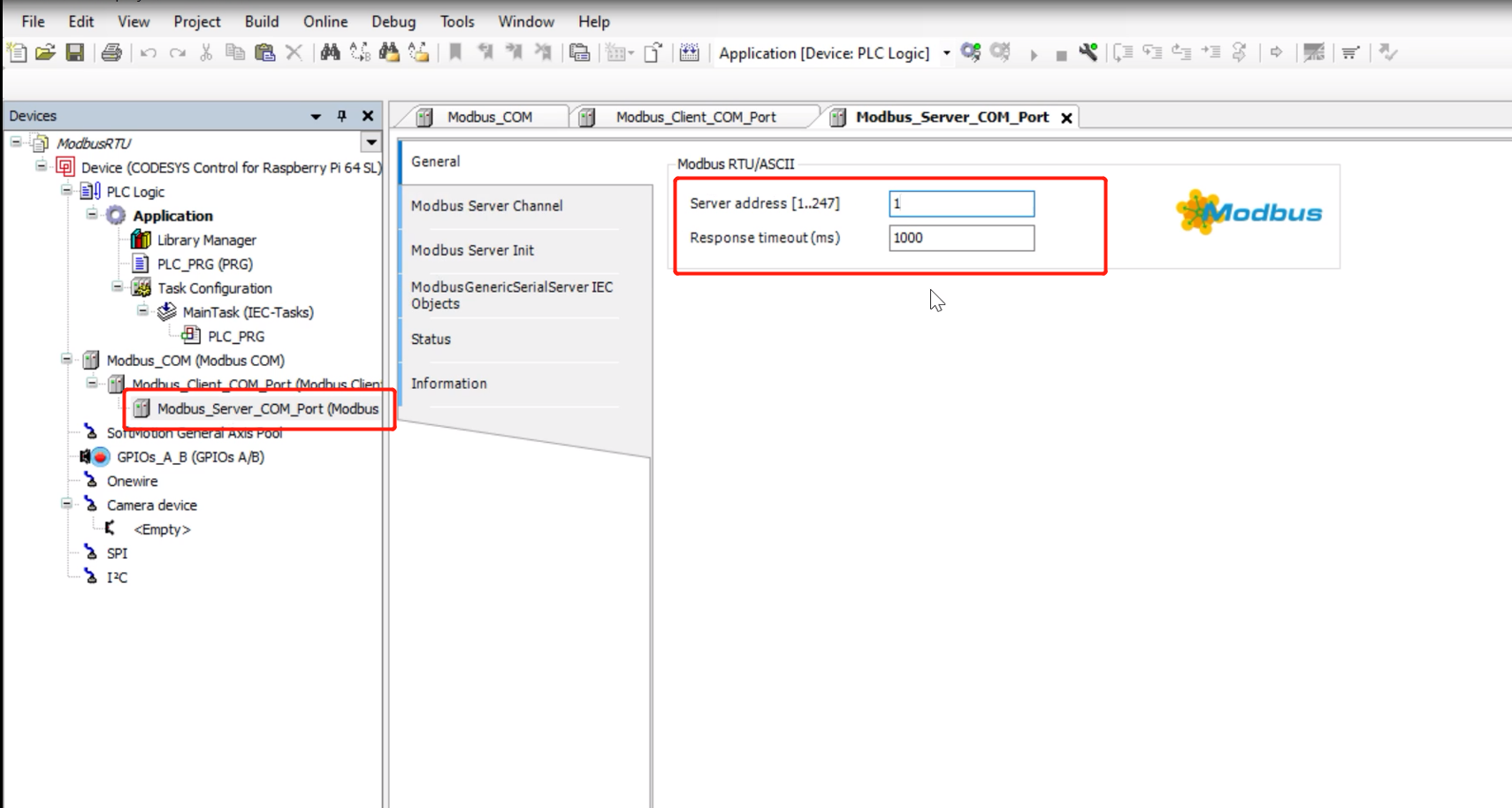
Step 11: Double-click the newly added slave device, and in General you can set the Server address and Response timeout properties
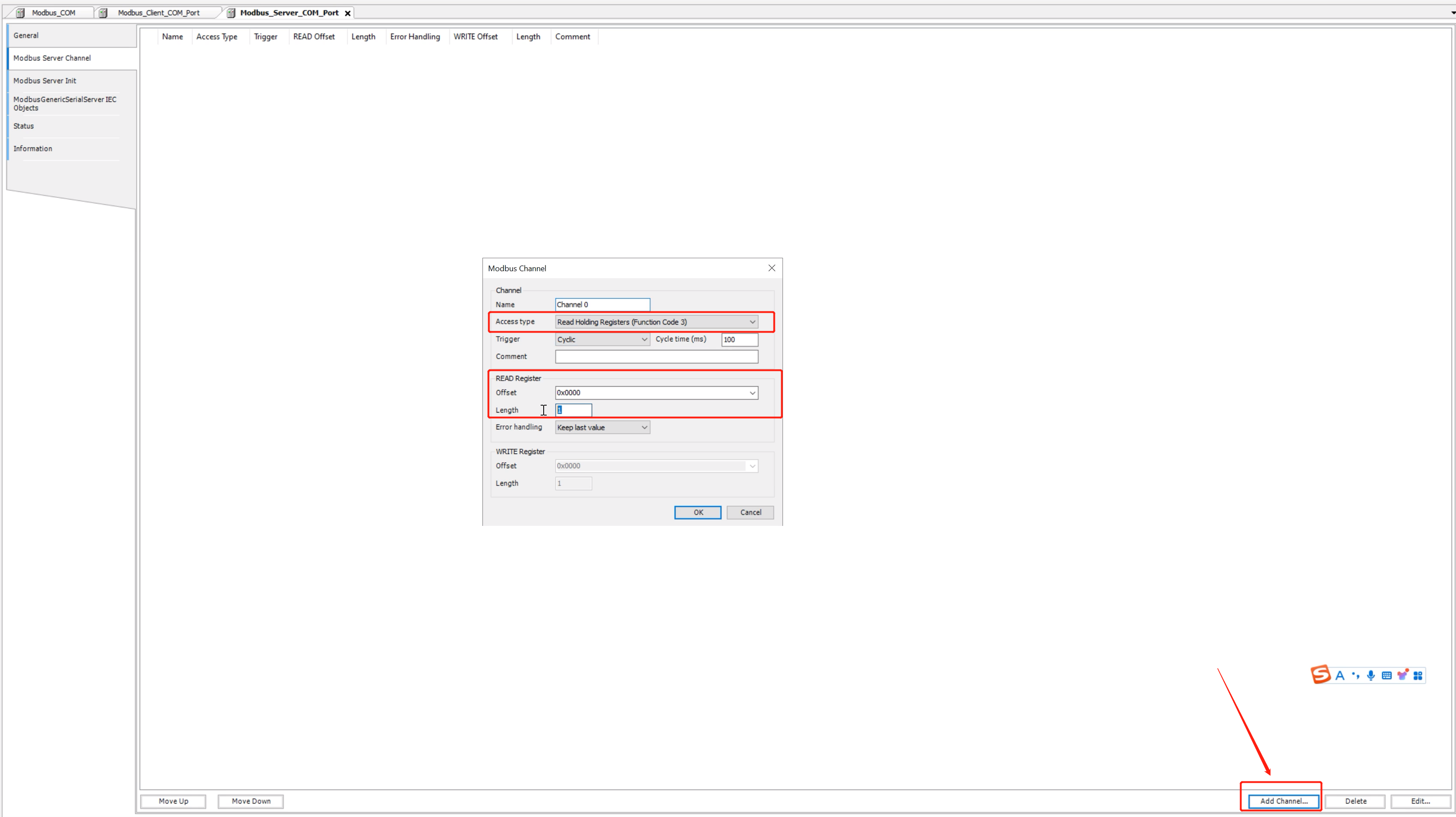
Step 12: Click Modbus Server Channel, then click Add Channel in the lower right corner to configure the operations that the master station will perform on the slave station, such as selecting the function code, the number of registers to be operated, etc. You can click Add Channel to add multiple operations
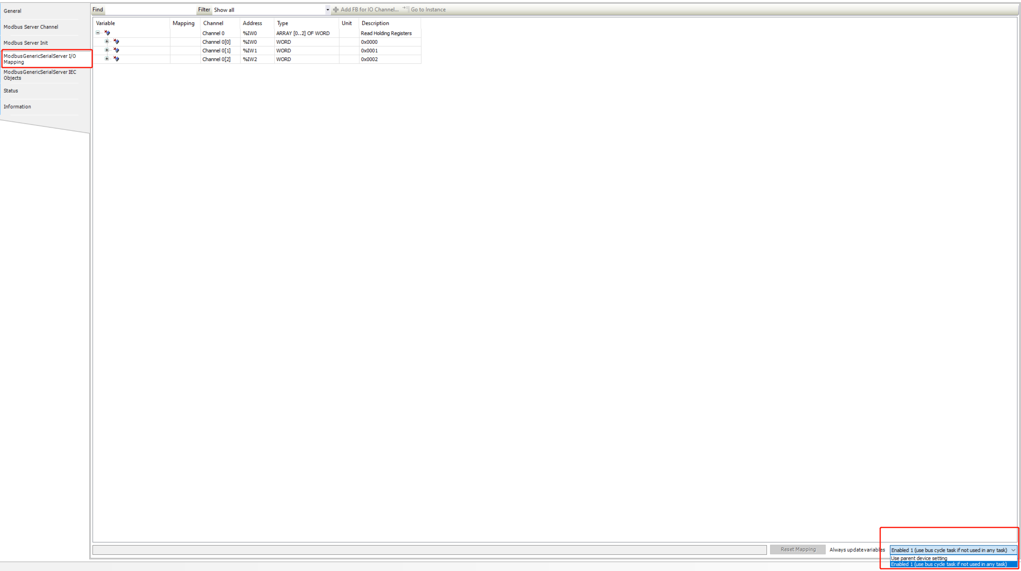
Step 13: Click ModbusGenericSerialServer I/O Mapping, where the data can be mapped to a specified variable, and select Enable 1 in the Always update variables column in the lower right corner. At this point, the configuration of Modbus Master is complete.
Modbus slave configuration
Step 1: Right click on the project and select Add Device to add a device

Step 2: Select Modbus ---> Modbus Serial Port ---> Modbus COM to add a Modbus serial port
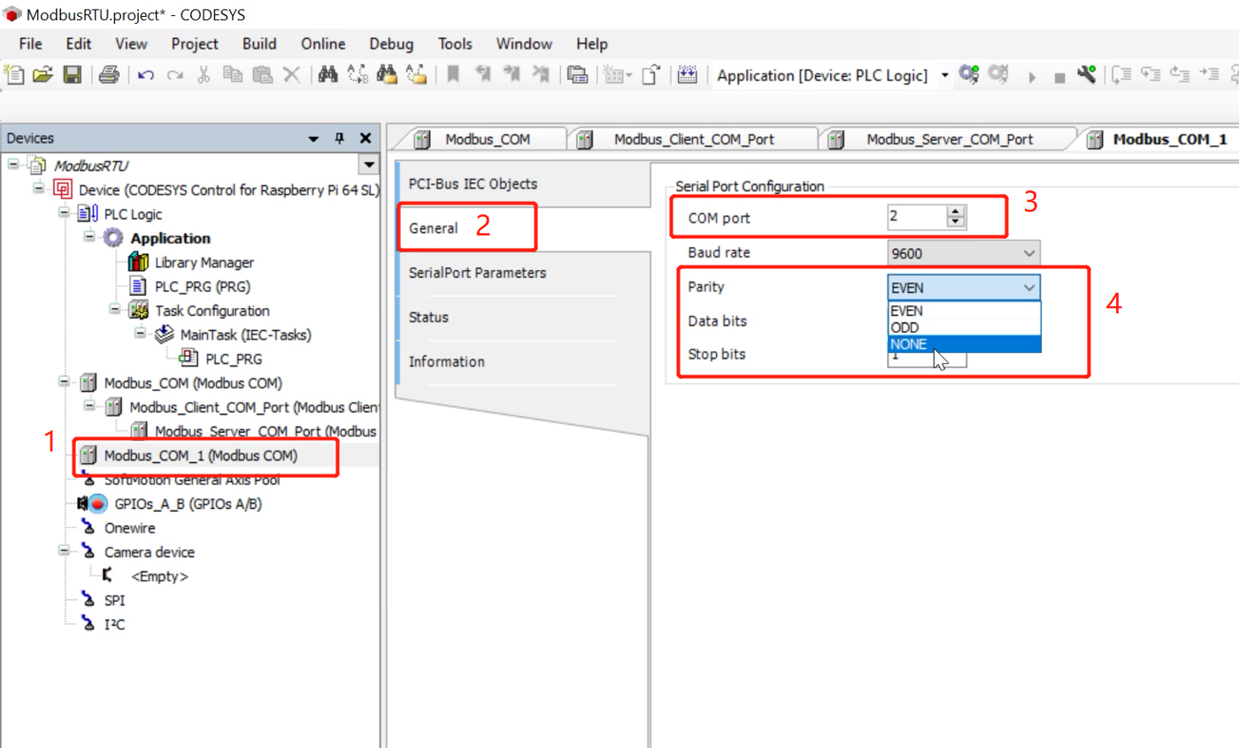
Step 3: Click the newly added Modbus serial port, select General, and configure the serial port number, baud rate and other information
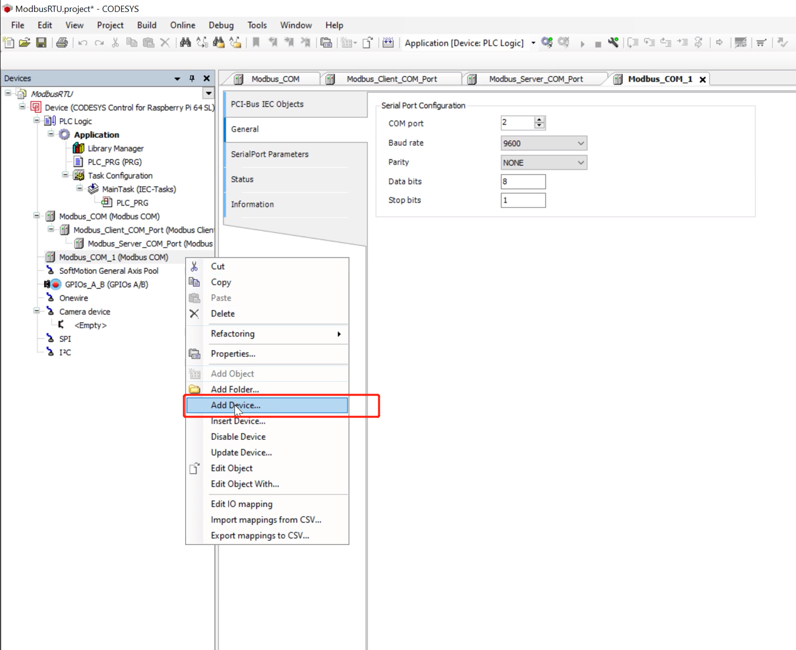
Step 4: Right-click the newly added Modbus serial port, select Add Device, and add the Modbus slave device
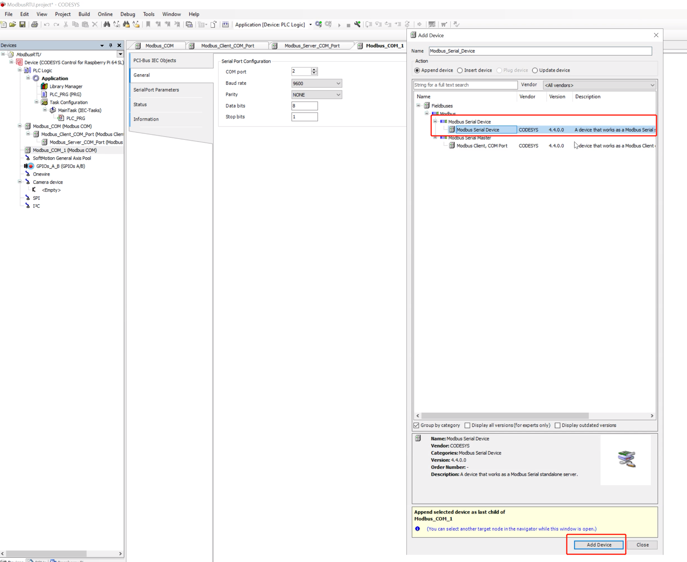
Step 5: Select Modbus ---> Modbus Serial Device ---> Modbus Serial Device to add a slave device
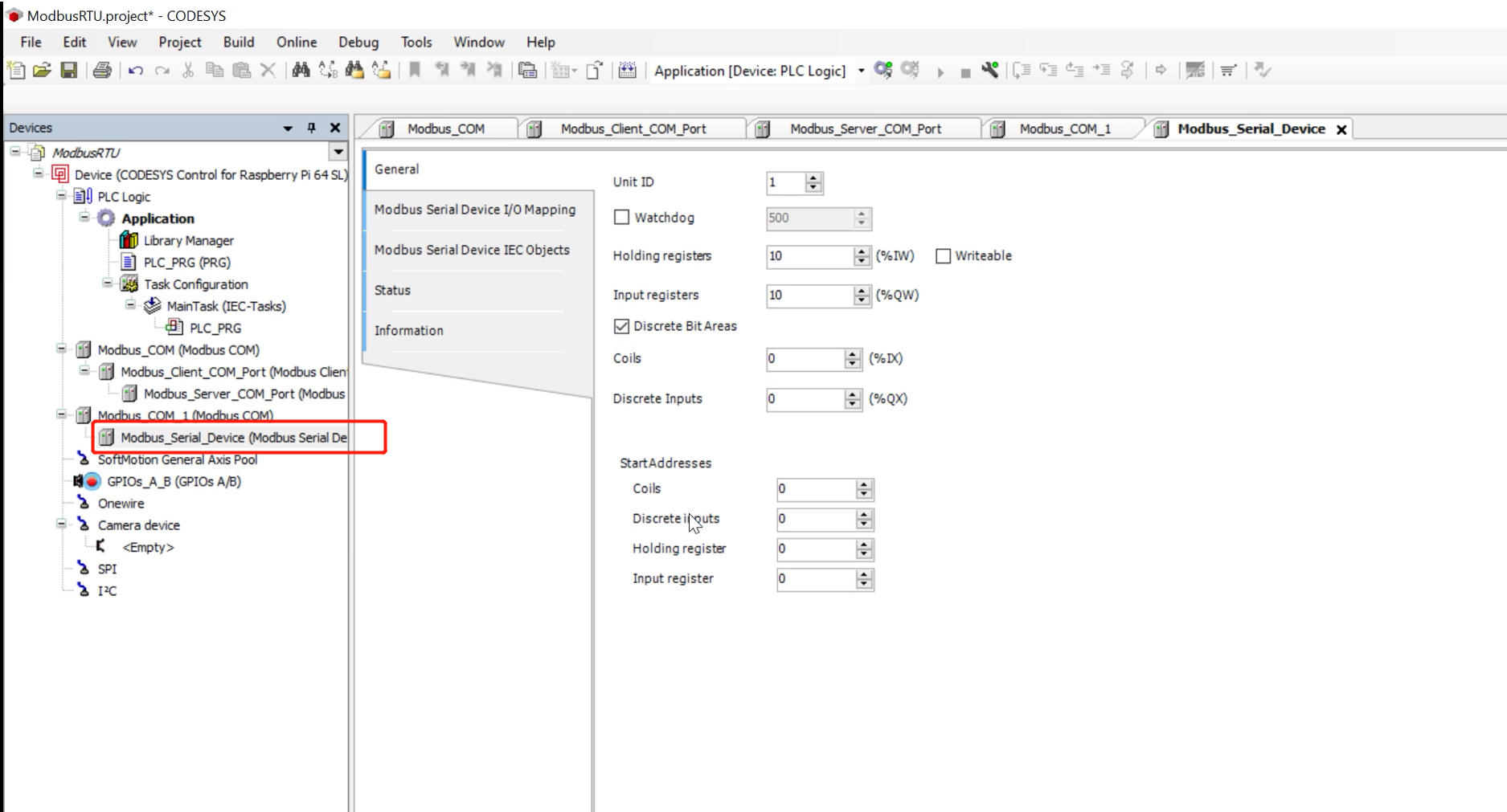
Step 6: Double-click the newly added slave device. In General, you can configure the properties of this slave, such as the number of registers and coils, address, etc.
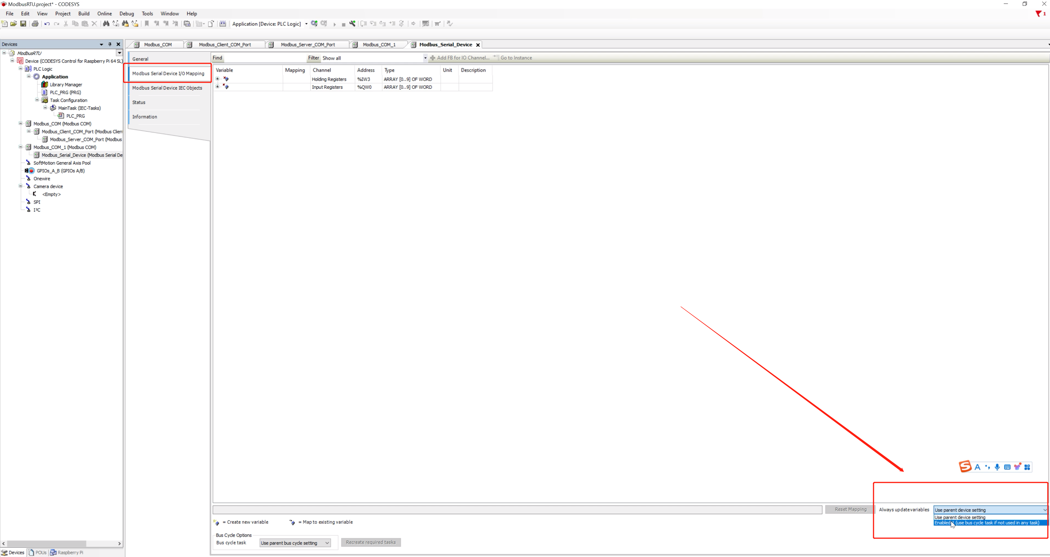
Step 7: Click Modbus Serial Device I/O Mapping, and select Enable 1 in the Always update variable in the lower right corner. The Modbus slave configuration is now complete
Modbus deployment
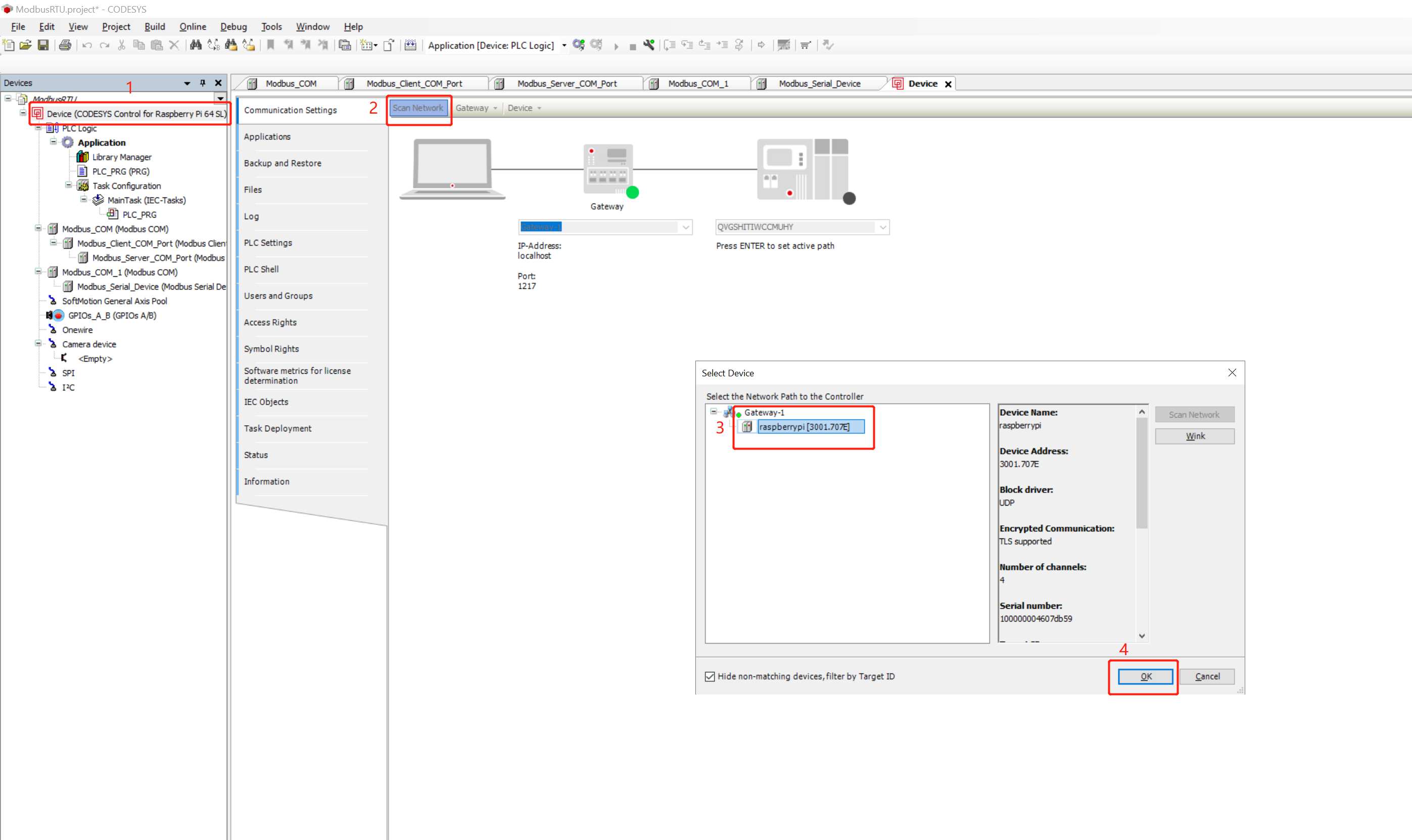
Step 1: Double-click the project, click Scan Network, then select your device, and click OK
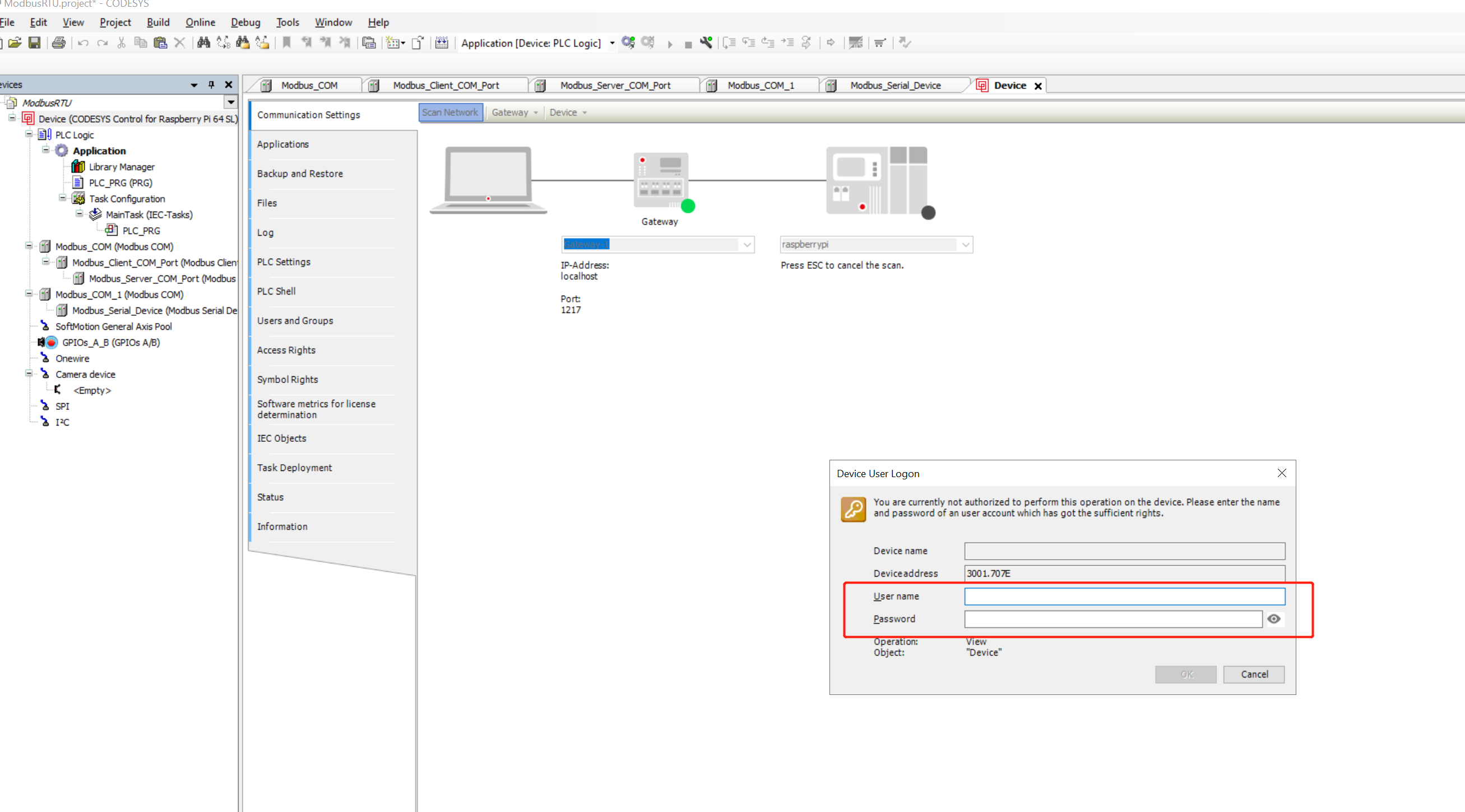
Step 2: Enter the reComputer R1000 username and password to connect to the device
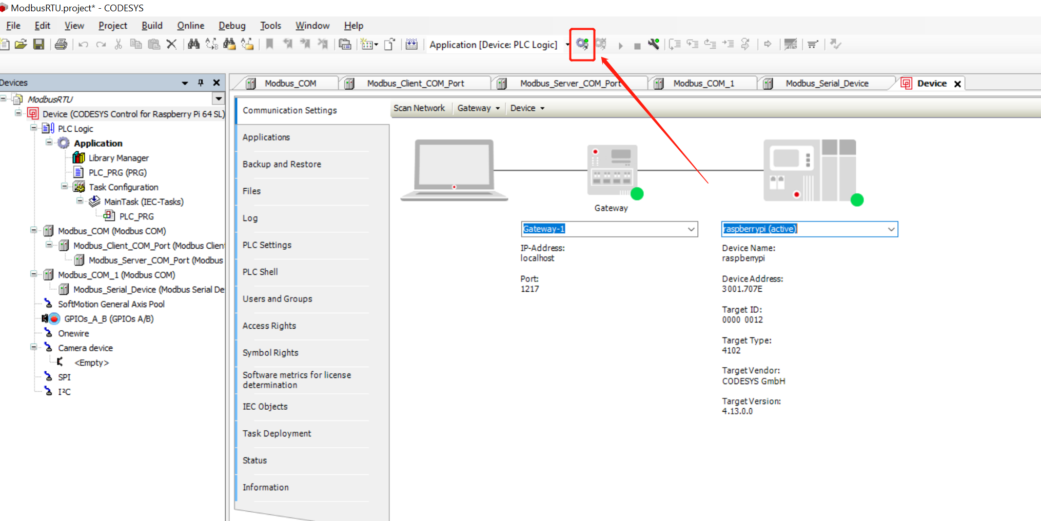
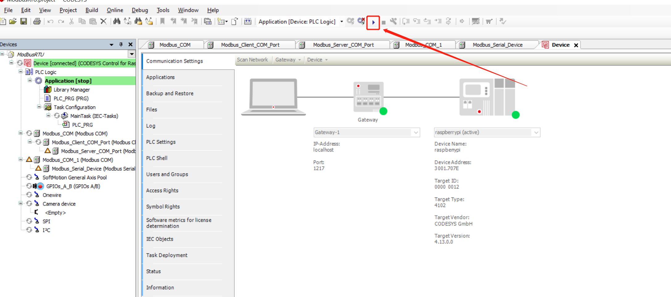
Step 3: Click the button as shown to deploy the project to reComputer R1000
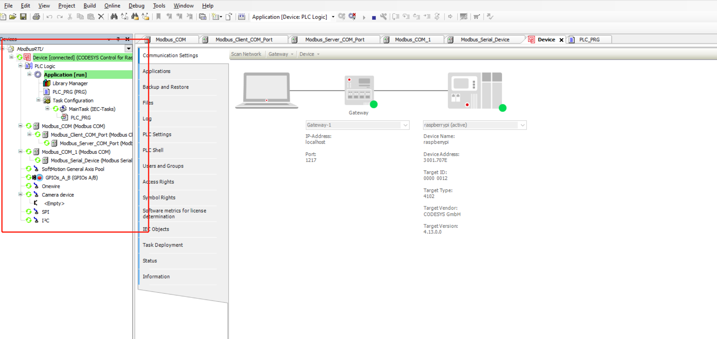
Step 4: Click the Start button to start the project. You can see that the indicator lights of the Modbus master and slave are both green, indicating that the Modbus communication is normal
Tech Support & Product Discussion
Thank you for choosing our products! We are here to provide you with different support to ensure that your experience with our products is as smooth as possible. We offer several communication channels to cater to different preferences and needs.