How to use rs485 and modbus with reComputer R1000
Introduction
This article mainly introduces how to use the 485 communication function of reComputer R1000, and tests the RS485 and Modbus communication functions.
Getting Start
Before you start this project, you may need to prepare your hardware and software in advance as described here.
Hardware Preparation
| reComputer R1000 |
|---|
 |
Software
- Using modbus poll on your W10 PC.You can also use other modbus testing tools
- Using modbusmechanic on reComputer R1000 and W10 PC.You can also use other modbus testing tools
- Using mobaxterm on your W10 PC.You can also use other serial port testing tools
- You need to download the minicom tool using the following command on the reComputer R1000:
sudo apt-get install minicom
Hardware Configuration
This test uses an RS485 to USB module to connect reComputer R1000 and W10 PC.
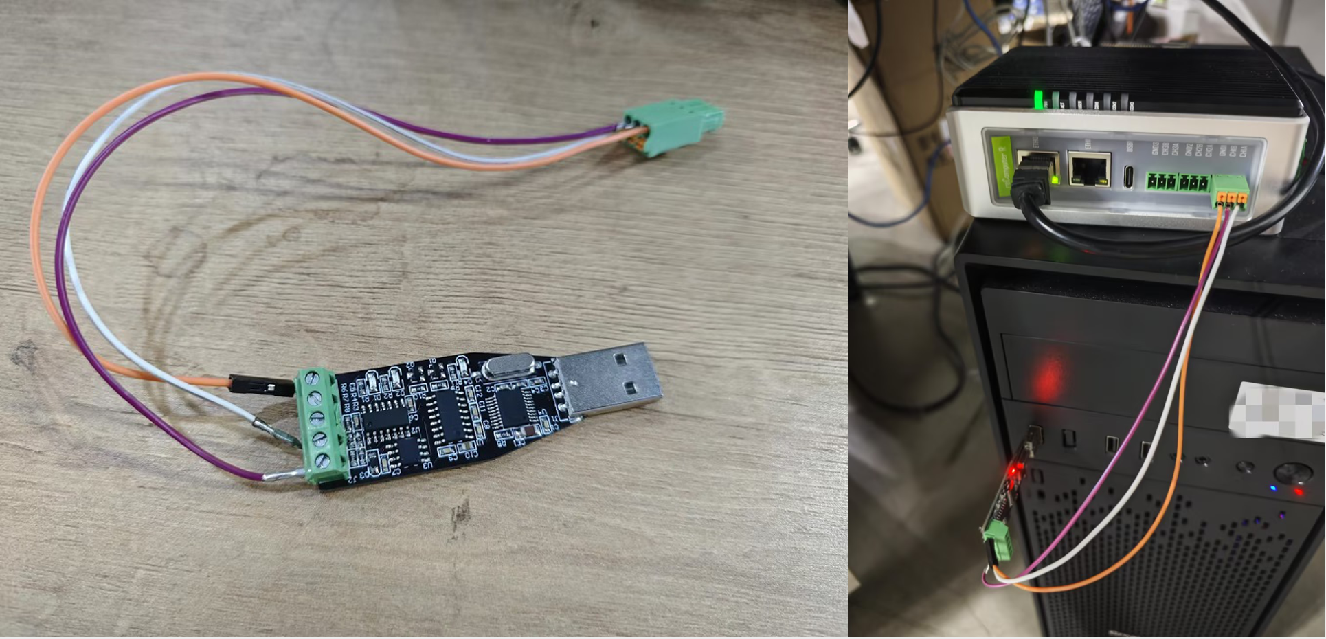
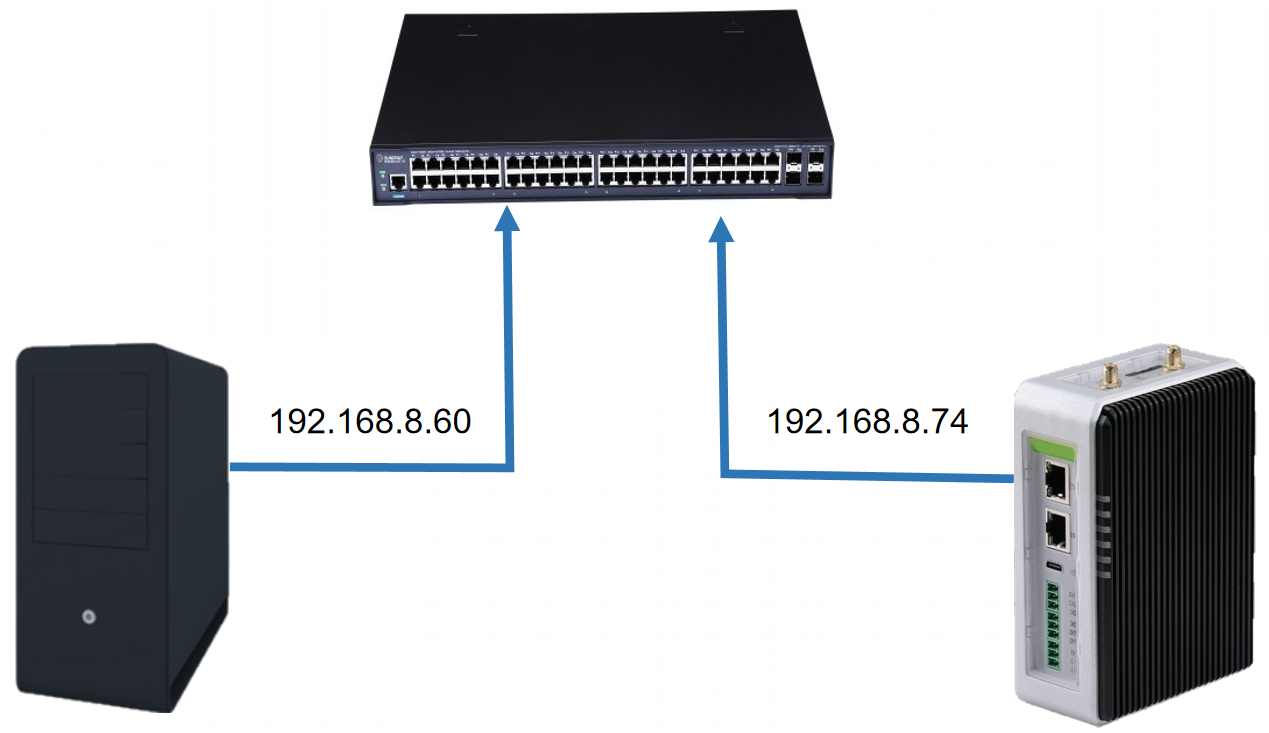
For ModbusTCP, we use Ethernet cables to connect the W10 PC and reComputer R1000 to a switch to ensure that they are on the same network segment.
Configure minicom on reComputer R1000v1.1
NOTE: Before you use RS485 with minicom please install r1000 drivers like this.
First, install minicom
Install minicom on both your host computer and reComputer r1000 with command below:
sudo apt install minicom
Second, configure your minicom as follows:
Open a terminal with Ctrl+Alt+T, and input command like below:
sudo minicom -D /dev/ttyAMA*
The ttyAMA* should be ttyAMA2, ttyAMA3 or ttyAMA4 depends on which RS485 you use.
And then type Ctal+A then type Z you will see minicom like below:
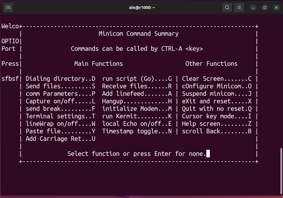
Type o to configure minicom, and select Serial port setup you will see like below:
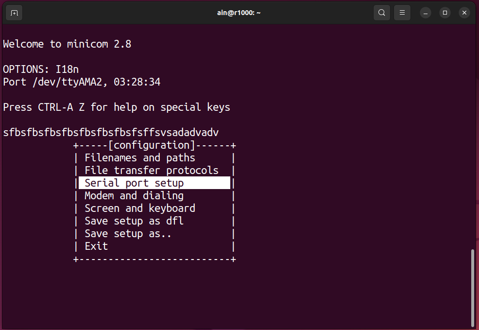
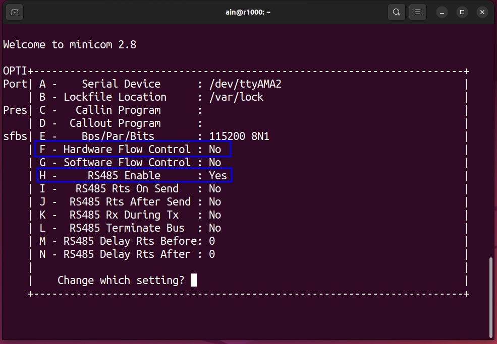
And the type F and H to make minicom to RS485 model, the result will show as below:
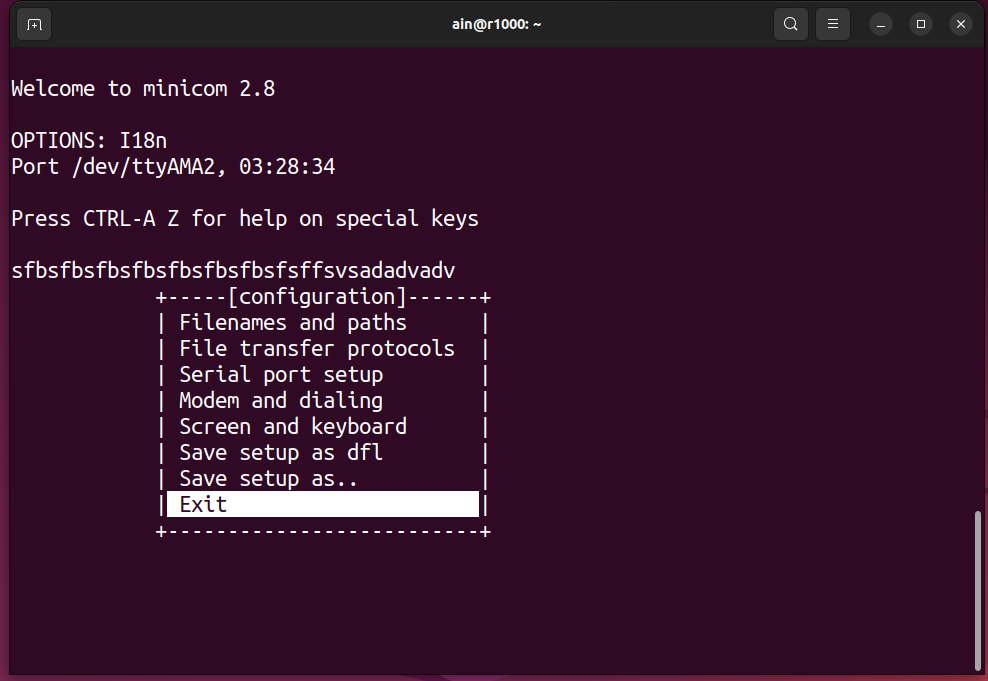
Finally, select Exit and type Enter to exit configure, like below:
Action required for reComputer R1000 v1.0
For reComputer R1000 v1.0, the DE pin of the built-in 485 transceiver is out of control by default, which means the interfaces can only transmit data unidirectionally (receive or send only).
To distinguish between the hardware revision (v1.0 and v1.1), you can refer to reComputer R1000 V1.1 Product change details.
We now have two solutions, one is to load a kernel module that hooks the UART driver, which we recommend you to use, and the other is an application layer based solution that simply calls the libgpiod to control the DE pins. You can choose one based on your needs.
Kernel module solution (recommended)
Installation
Firstly, you need to download the source code of the kernel module. It's a standalone repository, so you can directly clone it.
git clone https://github.com/bclswl0827/r1000v1-rs485-autoflow
cd r1000v1-rs485-autoflow
Next, you need to compile the kernel module.
make
If you are getting errors while compiling, you may need to install the kernel headers corresponding to your current running kernel. We assume that you are using Raspberry Pi OS, so you can use the following command to install the kernel headers.
sudo apt-get install linux-headers-$(uname -r)
After that, you can compile the kernel module again.
Load the kernel module
After it's got compiled, you can load the kernel module by running the following command.
sudo insmod r1000v1-rs485-autoflow.ko
If the kernel module loaded successfully, you should see the following message in the kernel log, check it with dmesg command.
[ 256.037465] r1000v1_rs485_autoflow: RS-485 interface has been hooked successfully
Now, you can use the minicom tool to test the RS485 communication. You can also use other serial port testing tools (e.g., picocom).
To load the kernel at boot time, you can add this module to the /etc/modules file using the following command.
echo "r1000v1_rs485_autoflow" | sudo tee -a /etc/modules
After the module is registered, you need to reboot the system to make the changes take effect.
sudo reboot
Unload the kernel module
To unload the kernel module, you can run the following command, and the built-in RS485 interface will return to receive-only mode.
sudo rmmod r1000v1-rs485-autoflow
Add the module with DKMS
DKMS (Dynamic Kernel Module Support) is a system that automates the building and installation of kernel modules, making it useful for managing modules across multiple kernel versions. By using DKMS, you can ensure that your modules remain compatible even after a kernel update.
To add this kernel module with DKMS, use the following command:
sudo make dkms_install
This command will register the module with DKMS, compile it, and install it for the current kernel version. When the kernel is upgraded in the future, DKMS will automatically rebuild and install the module for the new version, so you don't need to manually recompile it.
Application layer solution
Using script
- In addition to the methods mentioned in this article, we also provide a script that you can execute using the following command. This script can automatically create a new /dev/ttyx and then use the newly created device number to perform rs485/modbus rtu communication is enough
curl -sSL https://raw.githubusercontent.com/Seeed-Projects/R1000-RS485-Util/main/setup_rs485.sh | sudo bash
Manual setup
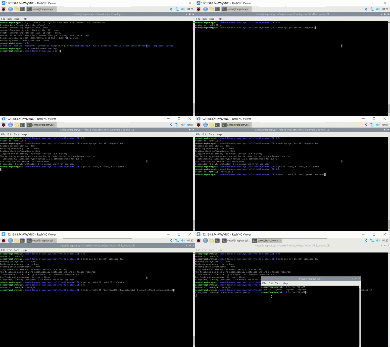
First, you need to download the C program provided by us, and then refer to the contents of the ReadMe. Compile and run.
git clone https://github.com/Seeed-Studio/seeed-linux-dtoverlays
cd seeed-linux-dtoverlays/tools/rs485_control_DE/
sudo apt-get install libgpiod-dev
gcc -o rs485_DE rs485_DE.c -lgpiod
sudo ./rs485_DE /dev/ttyAMA2 /dev/gpiochip0 6 /dev/ttyAMA10
This program will create a new ttyAMAx device, where the device number depends on the parameters you enter when running the program.
- The above example shows how to use one RS485 interface. If you want to use three 485 interfaces, you can use the following script to achieve it:
sudo ./rs485_DE /dev/ttyAMA2 /dev/gpiochip0 6 /dev/ttyAMA10 &
sudo ./rs485_DE /dev/ttyAMA3 /dev/gpiochip0 17 /dev/ttyAMA11 &
sudo ./rs485_DE /dev/ttyAMA5 /dev/gpiochip0 24 /dev/ttyAMA12 &
ttyAMA10ttyAMA12 corresponds to ttyAMA2ttyAMA5 one-to-one. Use ttyAMA10ttyAMA12 in your application for normal communication (ttyAMA2ttyAMA5 cannot be used, you need to use the device number newly created by the script)
Steps to use Modbus RTU testing
Step 1: Enter the following script on reComputer R1000 to open the minicom software
minicom -D /dev/ttyAMAx -b 9600
Among them, -D is followed by the device number you want to open, -b refers to the baud rate, and the device number needs to be the newly created device number in the first step.Then open MobaXterm on the W10 PC, create a new serial port terminal, select the serial port number, and the baud rate is 9600; finally, you can perform two-way communication with RS485. As shown in the figure, the content entered on the reComputer R1000 can be sent to via RS485. In W10 PC, the content entered on W10 PC can also be sent to reComputer R1000, and the two-way communication is normal.

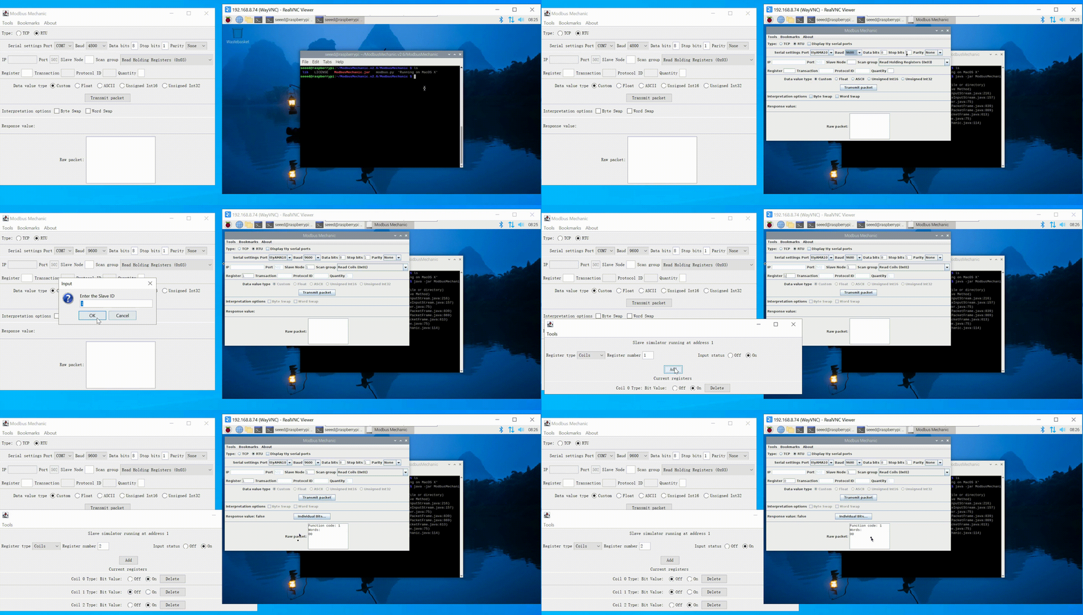
Step 2: After testing the RS485 function, you can perform the Modbus function test. This step allows the reComputer R1000 to be tested as a Modbus slave.Open the ModbusMechanic software on reComputer R1000, select the device number and baud rate, then click on the simulated slave function in the upper left corner to add two coils; then open Modbus poll in W10 as the master station to read the coils of the slave station. Then open the display window of Modbus poll, and you can see that the sending and receiving messages of Modbus RTU are normal.
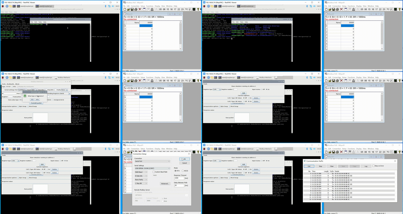
Step 3:This step allows the reComputer R1000 to be tested as a Modbus master. Open the ModbusMechanic software on both reComputer R1000 and W10 PC, and select the device number and baud rate. W10 PC refers to the third step of setting. Select Read Coils(0x01) on reComputer R1000 to read the coil of the slave, set Slave Node to 1, Register select the address you want to read, and finally click Transmit packet.
Steps to use the Modbus TCP testing
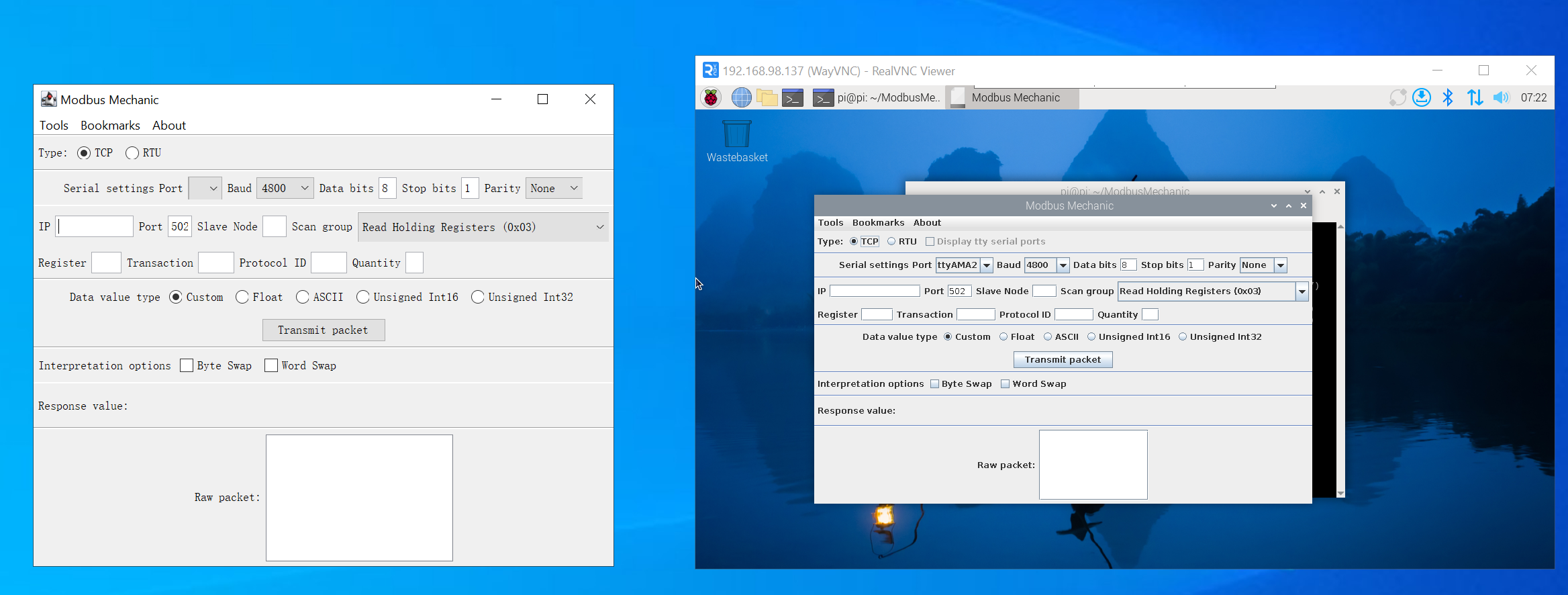
Step 1: Open modbusmechanic on Win10 PC and R1000
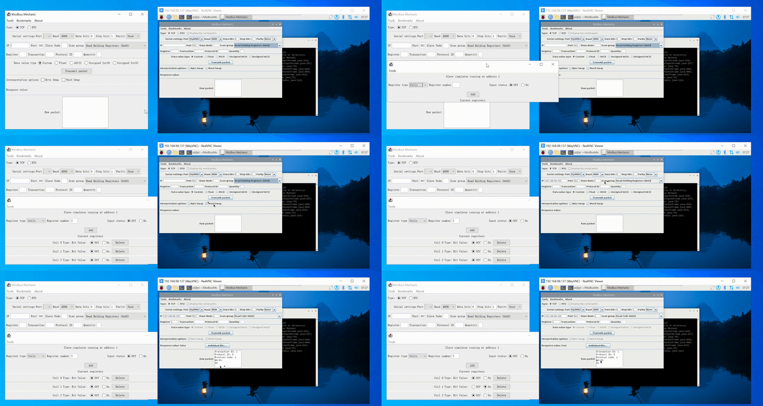
Step 2: R1000 acts as the modbus TCP host. Click Tool => Start Slave Simulator on W10 PC, select TCP for TYPE, select 1 for Slave ID, and then add Coils; then enter IP in R1000, and select Read Coil for Scan group. Enter Slave Node and Register, and finally click Transmit packet. You can see that the slave data has been successfully read.
Step 3: R1000 acts as a modbus TCP slave. Refer to the second step for configuration. You can see that R1000 can read data normally as a slave.
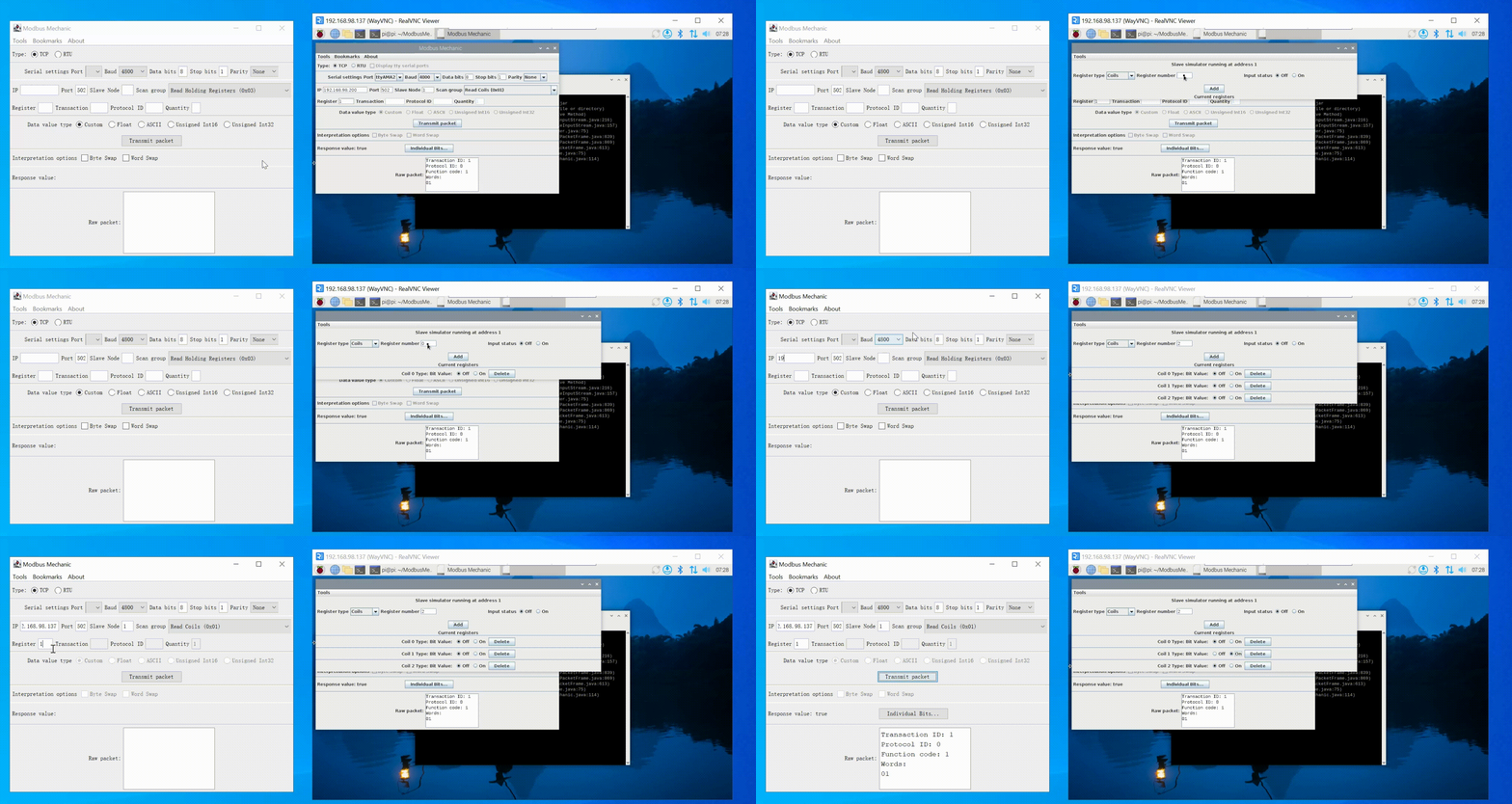
Running the Modbus TCP slave program in R1000 needs to listen to the 502 port, which may require sudo permissions. If your application cannot listen to the 502 port, please try to add permissions to it.
Tech Support & Product Discussion
Thank you for choosing our products! We are here to provide you with different support to ensure that your experience with our products is as smooth as possible. We offer several communication channels to cater to different preferences and needs.