GPIO controlling reSpeaker Flex with Xiao ESP32S3
Objective
This guide explains how to read and control GPIO pins on the XVF3800 voice processor using the I2C interface. You’ll learn how to:
- Read GPI and GPO pin statuses
- Understand GPIO mappings and their purpose
| reSpeaker Flex XVF3800 Linear with XIAO ESP32S3 | reSpeaker Flex XVF3800 Circular with XIAO ESP32S3 | |
|---|---|---|
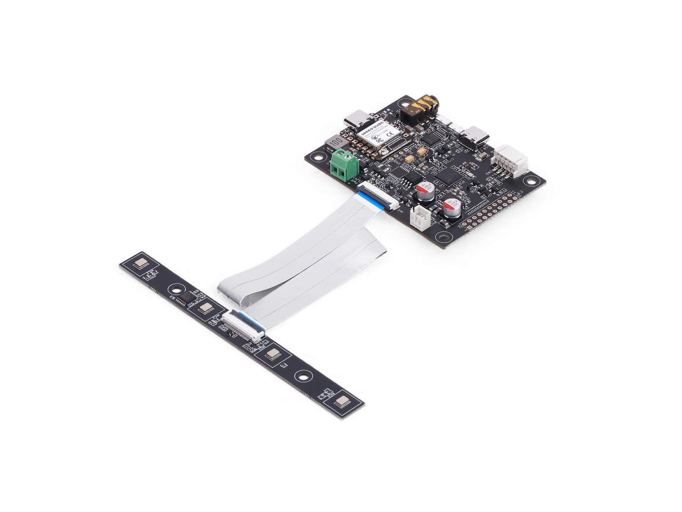 | 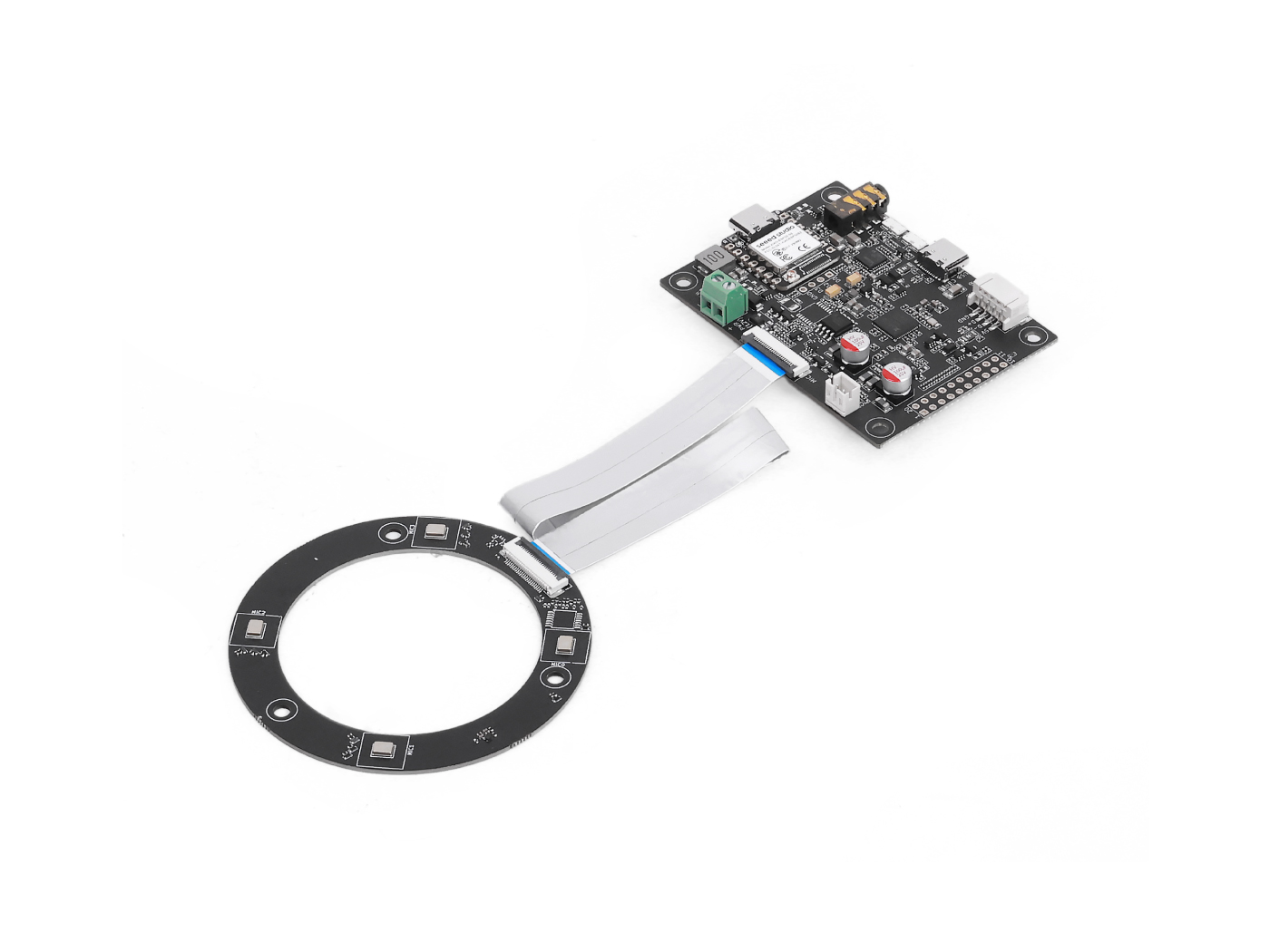 | |
GPIO Overview
| Pin Name | Direction | Function |
|---|---|---|
| X1D09 | Input (RO) | Boot button status / GPI0 |
| X1D13 | Input (RO) | Floating / GPI1 |
| X1D34 | Input (RO) | Floating / GPI2 |
| X0D11 | Output (RW) | Floating / GPO, shared with SPI MOSI |
| X0D30 | Output (RW) | SD/FAULT control |
| X0D31 | Output (RW) | PA / amplifier control |
| X0D32 | Output (RW) | XMOS GPIO 1 |
| X0D33 | Output (RW) | XMOS GPIO 2 |
| X0D39 | Output (RW) | Floating / GPO, shared with SPI MISO |
Read GPO Pin States
Goal: Check logic levels of all output-capable GPIOs (GPOs). Code Highlights:
- Sends a read request using:
- Resource ID: 20 (GPO)
- Command ID: 0 (GPO_READ_VALUES)
- Reads 5 GPO pins statues in order: X0D11 → X0D30 → X0D31 → X0D33 → X0D39
- Includes a status byte to validate the response
#include <Wire.h>

#define XMOS_ADDR 0x2C  // I2C 7-bit address

#define GPO_SERVICER_RESID 20
#define GPO_SERVICER_RESID_GPO_READ_VALUES 0
#define GPO_GPO_READ_NUM_BYTES 5

void setup() {
  Serial.begin(115200);
  while (!Serial);
  Wire.begin();
  delay(1000);
  Serial.println("XVF3800 GPO Read Test Starting...");
}

void loop() {
  uint8_t gpo_values[GPO_GPO_READ_NUM_BYTES] = {0};
  uint8_t status = 0xFF;

  bool success = read_gpo_values(gpo_values, &status);

  if (success) {
    Serial.print("I2C Communication SUCCESS. Status byte: 0x");
    Serial.print(status, HEX);
    Serial.print(" | GPO Output Values: ");
    for (uint8_t i = 0; i < GPO_GPO_READ_NUM_BYTES; i++) {
      Serial.print("0x");
      Serial.print(gpo_values[i], HEX);
      Serial.print(" ");
    }
    Serial.println();
  } else {
    Serial.println("Failed to read GPO values.");
  }

  delay(1000);
}

bool read_gpo_values(uint8_t *buffer, uint8_t *status) {
  const uint8_t resid = GPO_SERVICER_RESID;
  const uint8_t cmd = GPO_SERVICER_RESID_GPO_READ_VALUES | 0x80;
  const uint8_t read_len = GPO_GPO_READ_NUM_BYTES;

  // Step 1: Write command
  Wire.beginTransmission(XMOS_ADDR);
  Wire.write(resid);
  Wire.write(cmd);
  Wire.write(read_len + 1);
  uint8_t result = Wire.endTransmission();

  if (result != 0) {
    Serial.print("I2C Write Error: ");
    Serial.println(result);
    return false;
  }

  // Step 2: Read response (status + payload)
  Wire.requestFrom(XMOS_ADDR, (uint8_t)(read_len + 1));
  if (Wire.available() < read_len + 1) {
    Serial.println("I2C Read Error: Not enough data received.");
    return false;
  }

  *status = Wire.read();
  for (uint8_t i = 0; i < read_len; i++) {
    buffer[i] = Wire.read();
  }

  return true;
}
Read GPI Pin States
Goal: Check states of input-capable GPIOs (e.g., mute button status). Code Highlights:
- Sends command to:
- Resource ID: 36 (IO_CONFIG)
- Command ID: 6 (GPI_VALUE_ALL)
- Receives 3 GPI representing the state of X1D09, X1D13, and X1D34
#include <Wire.h>
#define XMOS_ADDR 0x2C // I2C 7-bit address of XVF3800
// Resource and command IDs for GPI
#define IO_CONFIG_SERVICER_RESID 36
#define IO_CONFIG_SERVICER_RESID_GPI_READ_VALUES 0
#define GPI_READ_NUM_BYTES 3 // From header: IO_CONFIG_SERVICER_RESID_GPI_READ_VALUES_NUM_VALUES
void setup() {
Serial.begin(115200);
while (!Serial);
Wire.begin();
delay(1000);
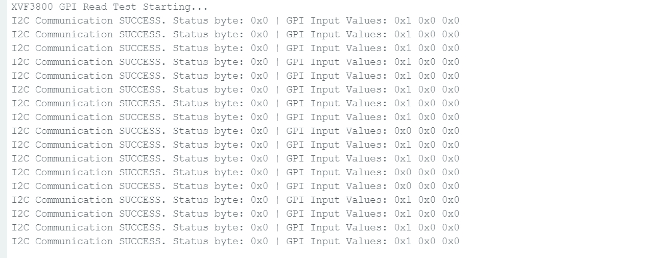
Serial.println("XVF3800 GPI Read Test Starting...");
}
void loop() {
uint8_t gpi_values[GPI_READ_NUM_BYTES] = {0};
uint8_t status = 0xFF;
bool success = read_gpi_values(gpi_values, &status);
if (success) {
Serial.print("I2C Communication SUCCESS. Status byte: 0x");
Serial.print(status, HEX);
Serial.print(" | GPI Input Values: ");
for (uint8_t i = 0; i < GPI_READ_NUM_BYTES; i++) {
Serial.print("0x");
Serial.print(gpi_values[i], HEX);
Serial.print(" ");
}
Serial.println();
} else {
Serial.println("Failed to read GPI values.");
}
delay(1000);
}
bool read_gpi_values(uint8_t *buffer, uint8_t *status) {
const uint8_t resid = IO_CONFIG_SERVICER_RESID;
const uint8_t cmd = IO_CONFIG_SERVICER_RESID_GPI_READ_VALUES | 0x80; // Read command
const uint8_t read_len = GPI_READ_NUM_BYTES;
// Step 1: Send the command
Wire.beginTransmission(XMOS_ADDR);
Wire.write(resid);
Wire.write(cmd);
Wire.write(read_len + 1); // +1 for status byte
uint8_t result = Wire.endTransmission();
if (result != 0) {
Serial.print("I2C Write Error: ");
Serial.println(result);
return false;
}
// Step 2: Read response (status + payload)
Wire.requestFrom(XMOS_ADDR, (uint8_t)(read_len + 1));
if (Wire.available() < read_len + 1) {
Serial.println("I2C Read Error: Not enough data received.");
return false;
}
*status = Wire.read(); // first byte is status
for (uint8_t i = 0; i < read_len; i++) {
buffer[i] = Wire.read();
}
return true;
}
Once you press the boot button, the state will change.
Tech Support & Product Discussion
Thank you for choosing our products! We are here to provide you with different support to ensure that your experience with our products is as smooth as possible. We offer several communication channels to cater to different preferences and needs.