Controlling reSpeaker XVF3800 GPIO via XIAO ESP32-S3
Objective
This guide explains how to read and control GPIO pins on the XVF3800 voice processor using the I2C interface. You’ll learn how to:
- Read GPI and GPO pin statuses
- Control output pins (e.g., mute microphone, control LED, amplifier)
- Understand GPIO mappings and their purpose
GPIO Overview
The reSpeaker XVF3800 exposes 3 input pins (GPI) and 5 output pins (GPO) for external control. You can use these to read button states or control hardware like the mute LED, amplifier, or LEDs.
| Pin Name | Direction | Function |
|---|---|---|
| X1D09 | Input (RO) | Mute button status (high when released) |
| X1D13 | Input (RO) | Floating |
| X1D34 | Input (RO) | Floating |
| X0D11 | Output (RW) | Floating |
| X0D30 | Output (RW) | Mute LED + mic mute control (high = mute) |
| X0D31 | Output (RW) | Amplifier enable (low = enabled) |
| X0D33 | Output (RW) | WS2812 LED power control (high = on) |
| X0D39 | Output (RW) | Floating |
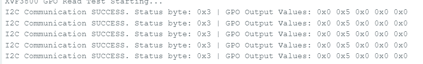
Read GPO Pin States
Goal: Check logic levels of all output-capable GPIOs (GPOs). Code Highlights:
- Sends a read request using:
- Resource ID: 20 (GPO)
- Command ID: 0 (GPO_READ_VALUES)
- Reads 5 GPO pins statues in order: X0D11 → X0D30 → X0D31 → X0D33 → X0D39
- Includes a status byte to validate the response
#include <Wire.h>

#define XMOS_ADDR 0x2C  // I2C 7-bit address

#define GPO_SERVICER_RESID 20
#define GPO_SERVICER_RESID_GPO_READ_VALUES 0
#define GPO_GPO_READ_NUM_BYTES 5

void setup() {
  Serial.begin(115200);
  while (!Serial);
  Wire.begin();
  delay(1000);
  Serial.println("XVF3800 GPO Read Test Starting...");
}

void loop() {
  uint8_t gpo_values[GPO_GPO_READ_NUM_BYTES] = {0};
  uint8_t status = 0xFF;

  bool success = read_gpo_values(gpo_values, &status);

  if (success) {
    Serial.print("I2C Communication SUCCESS. Status byte: 0x");
    Serial.print(status, HEX);
    Serial.print(" | GPO Output Values: ");
    for (uint8_t i = 0; i < GPO_GPO_READ_NUM_BYTES; i++) {
      Serial.print("0x");
      Serial.print(gpo_values[i], HEX);
      Serial.print(" ");
    }
    Serial.println();
  } else {
    Serial.println("Failed to read GPO values.");
  }

  delay(1000);
}

bool read_gpo_values(uint8_t *buffer, uint8_t *status) {
  const uint8_t resid = GPO_SERVICER_RESID;
  const uint8_t cmd = GPO_SERVICER_RESID_GPO_READ_VALUES | 0x80;
  const uint8_t read_len = GPO_GPO_READ_NUM_BYTES;

  // Step 1: Write command
  Wire.beginTransmission(XMOS_ADDR);
  Wire.write(resid);
  Wire.write(cmd);
  Wire.write(read_len + 1);
  uint8_t result = Wire.endTransmission();

  if (result != 0) {
    Serial.print("I2C Write Error: ");
    Serial.println(result);
    return false;
  }

  // Step 2: Read response (status + payload)
  Wire.requestFrom(XMOS_ADDR, (uint8_t)(read_len + 1));
  if (Wire.available() < read_len + 1) {
    Serial.println("I2C Read Error: Not enough data received.");
    return false;
  }

  *status = Wire.read();
  for (uint8_t i = 0; i < read_len; i++) {
    buffer[i] = Wire.read();
  }

  return true;
}
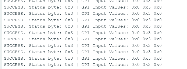
Read GPI Pin States
Goal: Check states of input-capable GPIOs (e.g., mute button status). Code Highlights:
- Sends command to:
- Resource ID: 36 (IO_CONFIG)
- Command ID: 6 (GPI_VALUE_ALL)
- Receives 3 GPI representing the state of X1D09, X1D13, and X1D34
#include <Wire.h>

#define XMOS_ADDR 0x2C  // I2C 7-bit address of XVF3800

// Resource and command IDs for GPI
#define IO_CONFIG_SERVICER_RESID 36
#define IO_CONFIG_SERVICER_RESID_GPI_READ_VALUES 0
#define GPI_READ_NUM_BYTES 3   // From header: IO_CONFIG_SERVICER_RESID_GPI_READ_VALUES_NUM_VALUES

void setup() {
  Serial.begin(115200);
  while (!Serial);
  Wire.begin();
  delay(1000);
  Serial.println("XVF3800 GPI Read Test Starting...");
}

void loop() {
  uint8_t gpi_values[GPI_READ_NUM_BYTES] = {0};
  uint8_t status = 0xFF;

  bool success = read_gpi_values(gpi_values, &status);

  if (success) {
    Serial.print("I2C Communication SUCCESS. Status byte: 0x");
    Serial.print(status, HEX);
    Serial.print(" | GPI Input Values: ");
    for (uint8_t i = 0; i < GPI_READ_NUM_BYTES; i++) {
      Serial.print("0x");
      Serial.print(gpi_values[i], HEX);
      Serial.print(" ");
    }
    Serial.println();
  } else {
    Serial.println("Failed to read GPI values.");
  }

  delay(1000);
}

bool read_gpi_values(uint8_t *buffer, uint8_t *status) {
  const uint8_t resid = IO_CONFIG_SERVICER_RESID;
  const uint8_t cmd = IO_CONFIG_SERVICER_RESID_GPI_READ_VALUES | 0x80;  // Read command
  const uint8_t read_len = GPI_READ_NUM_BYTES;

  // Step 1: Send the command
  Wire.beginTransmission(XMOS_ADDR);
  Wire.write(resid);
  Wire.write(cmd);
  Wire.write(read_len + 1);  // +1 for status byte
  uint8_t result = Wire.endTransmission();

  if (result != 0) {
    Serial.print("I2C Write Error: ");
    Serial.println(result);
    return false;
  }

  // Step 2: Read response (status + payload)
  Wire.requestFrom(XMOS_ADDR, (uint8_t)(read_len + 1));
  if (Wire.available() < read_len + 1) {
    Serial.println("I2C Read Error: Not enough data received.");
    return false;
  }

  *status = Wire.read();  // first byte is status
  for (uint8_t i = 0; i < read_len; i++) {
    buffer[i] = Wire.read();
  }

  return true;
}
Write to GPO Pin – Mute Mic Example
Goal: Control an output GPIO, e.g., mute microphone by toggling GPIO 30 (X0D30). Code Highlights:
- Sends a write command to:
- Resource ID: 20
- Command ID: 1 (GPO_WRITE_VALUE)
- Payload: pin number, value
e.g., {30, 1} to mute
Convenience Functions:
- muteMic() → sets GPIO 30 HIGH to mute mic and turn on red LED
- unmuteMic() → sets GPIO 30 LOW to unmute mic and turn off LED
#include <Wire.h>

// Define the 7-bit I2C address of the XVF3800 device
#define XMOS_ADDR 0x2C

// Define XVF3800 Resource and Command IDs
#define GPO_SERVICER_RESID 20                         // Resource ID for GPIO Output (GPO)
#define GPO_SERVICER_RESID_GPO_WRITE_VALUE 1          // Command ID to write value to GPIO
#define IO_CONFIG_SERVICER_RESID 36                   // Resource ID for IO Configuration
#define IO_CONFIG_SERVICER_RESID_GPI_VALUE_ALL 6      // Command ID to read all GPIO input values

void setup() {
  Wire.begin();                 // Initialize I2C communication
  Serial.begin(115200);        // Initialize serial communication for debugging
  delay(1000);                 // Short delay to allow device startup

  Serial.println("Muting Mic (Setting GPIO 30 HIGH)");
  muteMic();                   // Set GPIO 30 HIGH to mute microphone
  delay(5000);                 // Wait for 5 seconds

  Serial.println("Unmuting Mic (Setting GPIO 30 LOW)");
  unmuteMic();                 // Set GPIO 30 LOW to unmute microphone
  delay(3000);                 // Wait for 3 seconds

  Serial.println("Reading GPIO Status...");
  readGPIOStatus();            // Read and print the status of all GPIOs
}

void loop() {
  // Empty loop - no repeated actions for now
}

// Function to set GPIO 30 to a specific logic level (0 = LOW, 1 = HIGH)
void setGPIO30(uint8_t level) {
  uint8_t payload[2] = {30, level};  // Payload format: [GPIO index, value]
  xmos_write_bytes(GPO_SERVICER_RESID, GPO_SERVICER_RESID_GPO_WRITE_VALUE, payload, 2);

  Serial.print("Command Sent: GPIO 30 = ");
  Serial.println(level);
}

// Convenience function to mute the microphone (set GPIO 30 HIGH)
void muteMic() {
  setGPIO30(1);  // Logic HIGH to mute
}

// Convenience function to unmute the microphone (set GPIO 30 LOW)
void unmuteMic() {
  setGPIO30(0);  // Logic LOW to unmute
}

// Function to write a sequence of bytes over I2C to the XVF3800
void xmos_write_bytes(uint8_t resid, uint8_t cmd, uint8_t *value, uint8_t write_byte_num) {
  Wire.beginTransmission(XMOS_ADDR); // Begin I2C transmission to XVF3800
  Wire.write(resid);                 // Write the resource ID
  Wire.write(cmd);                   // Write the command ID
  Wire.write(write_byte_num);       // Write number of payload bytes
  for (uint8_t i = 0; i < write_byte_num; i++) {
    Wire.write(value[i]);           // Write each payload byte
  }
  Wire.endTransmission();           // End the I2C transmission
}

// Function to read the status of all GPIO inputs (32 bits) from XVF3800
void readGPIOStatus() {
  uint8_t buffer[4] = {0};  // Buffer to hold the 4-byte GPIO status response

  // --- Write phase: Send read request ---
  Wire.beginTransmission(XMOS_ADDR);                        // Begin I2C write transaction
  Wire.write(IO_CONFIG_SERVICER_RESID);                     // Write the resource ID for IO config
  Wire.write(IO_CONFIG_SERVICER_RESID_GPI_VALUE_ALL);       // Write the command ID to get all GPIO values
  Wire.write(1);                                             // Payload length (1 byte)
  Wire.endTransmission(false);                              // End transmission with repeated start (no stop)

  // --- Read phase: Read response from device ---
  Wire.requestFrom(XMOS_ADDR, 5); // Request 5 bytes: 1 status byte + 4 data bytes

  if (Wire.available() < 5) {
    Serial.println("Error: Not enough bytes received from XVF3800.");
    return;
  }

  uint8_t status = Wire.read();  // Read the status byte (should be 0 for success)

  // Read the 4-byte GPIO input status value
  for (int i = 0; i < 4; i++) {
    buffer[i] = Wire.read();
  }

  // Combine 4 bytes into a single 32-bit unsigned integer
  uint32_t gpio_status = ((uint32_t)buffer[3] << 24) |
                         ((uint32_t)buffer[2] << 16) |
                         ((uint32_t)buffer[1] << 8)  |
                         ((uint32_t)buffer[0]);

  Serial.print("GPIO Status Register = 0x");
  Serial.println(gpio_status, HEX);

  // Check and print the state of GPIO 30 specifically
  bool gpio30 = (gpio_status >> 30) & 0x01;
  Serial.print("GPIO 30 State: ");
  Serial.println(gpio30 ? "HIGH (Muted)" : "LOW (Unmuted)");
}
Tech Support & Product Discussion
Thank you for choosing our products! We are here to provide you with different support to ensure that your experience with our products is as smooth as possible. We offer several communication channels to cater to different preferences and needs.