Using I2C Commands to Control reSpeaker XVF3800 USB Mic Array with XIAO ESP32S3
Introduction
This section provides the I2C control command list for the ReSpeaker XVF3800, along with I2C read/write examples and hardware signal-path diagrams for the two operating modes. For an application example of controlling the ReSpeaker XVF3800 via the I2C interface, please refer to the Device Control section.
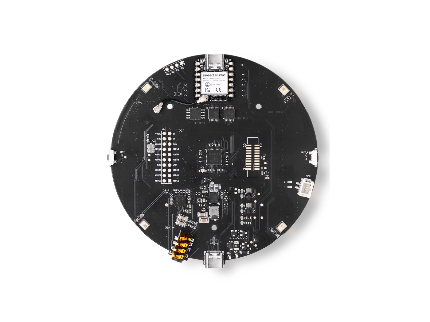
reSpeaker Hardware Signal Path Diagram
I2S Mode Signal Path
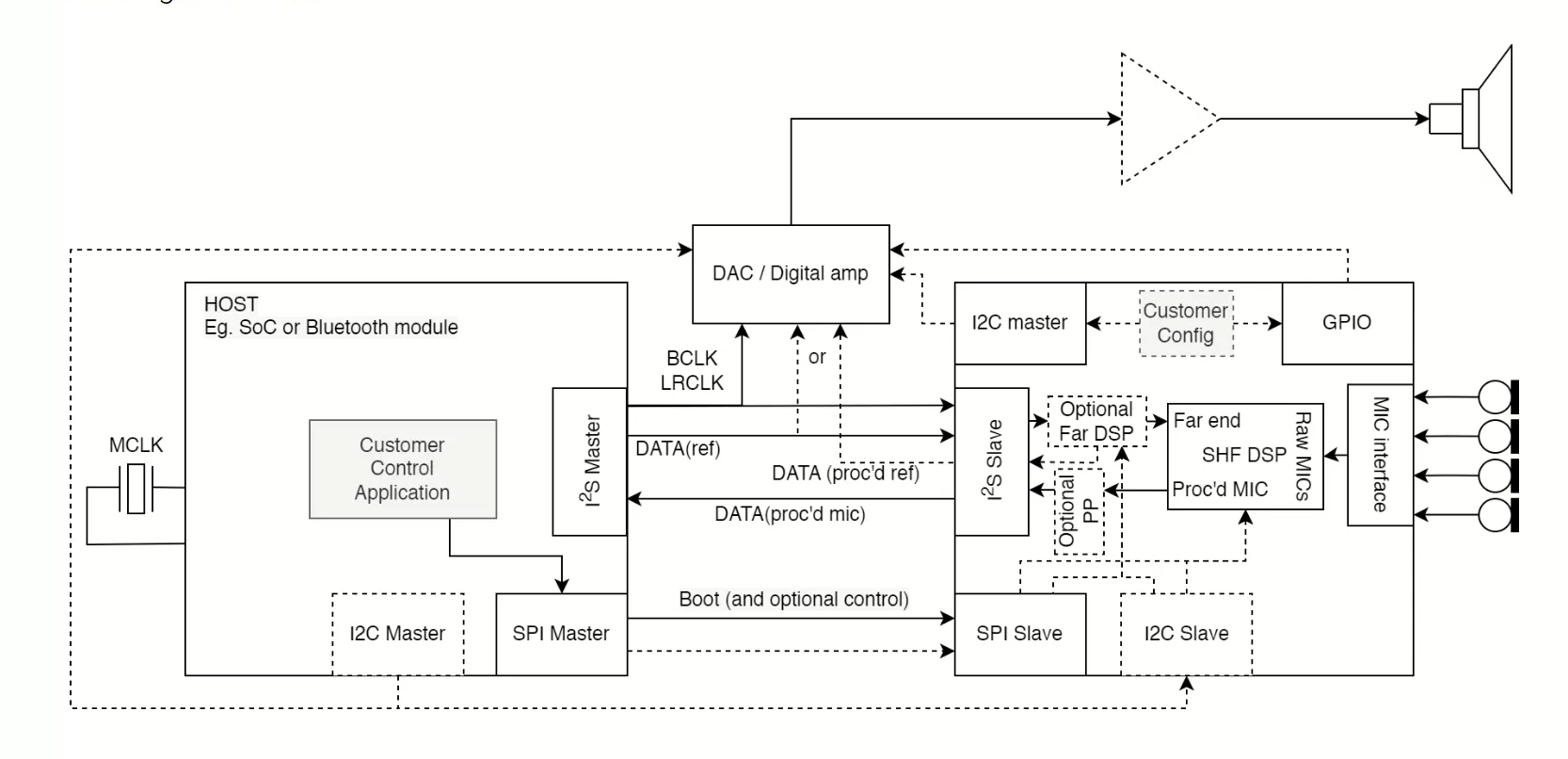
Recording Path
The microphones capture raw data, which is processed by the algorithm modules. The processed data is then read by the host controller via the I2S interface.
Playback Path
In I2S mode, the audio playback path is divided into two routes: Host → XVF3800 → DAC and Host → DAC.
1. Host → XVF3800 → DAC
The host controller sends audio data to the XVF3800 via the I2S interface. The data is processed by the Optional Far DSP block, then re-transmitted to the DAC for playback via the I2S bus.
For an application example of playback via this path, please refer to the reSpeaker XVF3800 Record and Playback Audio Using I2S section.
2. Host → DAC
The host controller sends audio data directly to the DAC for playback via the I2S interface, bypassing the XVF3800.
For an application example of playback via this path, please refer to the reSpeaker XVF3800 Audio Playback and Volume Control via I2C section.
Control Path
The control path, like the playback path, is divided into two routes:
1. Host → XVF3800 → DAC
- Host ↔ XVF3800 communication: The host acts as the I2C Master and the XVF3800 acts as the I2C Slave. The host uses I2C to configure the XVF3800's Optional Far DSP, Optional PP, GPIO, and other blocks.
- XVF3800 ↔ DAC communication: The XVF3800 acts as the I2C Master and the DAC acts as the I2C Slave. The XVF3800 controls the DAC playback via I2C.
2. Host → DAC
The host communicates directly with the DAC. The host uses I2C to directly control the DAC for audio playback and volume control.
USB Mode Signal Path
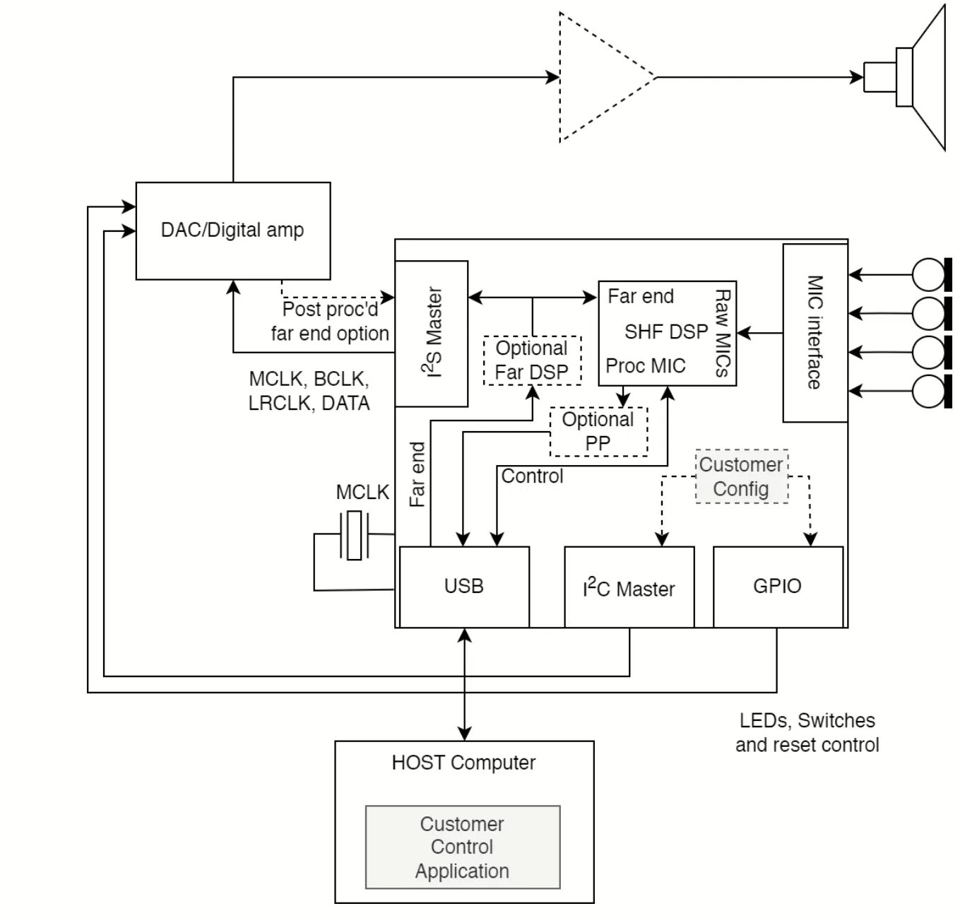
In USB mode, there is only one data path: Host → XVF3800 → DAC, which is divided into two segments: Host → XVF3800 and XVF3800 → DAC.
-
Host ↔ XVF3800: Communication is via USB. Both the audio data (the raw data captured by the microphones, which is processed by the algorithm modules) and the control data (for configuring the XVF3800's Optional Far DSP, Optional PP, GPIO, and other blocks) are transmitted over USB.
-
XVF3800 ↔ DAC: Communication is via I2C and I2S. The XVF3800 acts as the I2C Master and I2S Master to control the DAC for audio playback.
For an application example of playback via this path, please refer to the reSpeaker XVF3800 Control with Python section.
I2C Frame Format
Write Operation
[resid] [cmd] [write_byte_num] [data...]
| Field | Description |
|---|---|
resid | Resource ID |
cmd | Command ID |
write_byte_num | Number of data bytes to write |
data... | Data bytes to be written |
Read Operation (write command first, then read response):
Step 1 (Write): [resid] [cmd | 0x80] [read_len + 1]
Step 2 (Read):  [status] [data...]
| Field | Description |
|---|---|
cmd|0x80 | Command ID with the MSB set to 1, indicating a read operation |
read_len + 1 | Expected number of bytes to read (+1 for the status byte) |
status | Response status byte (0 = success, 64 = retry) |
data... | Returned data bytes |
For the detailed I2C command list, please refer to the I2C Command List section.
Arduino Read And Write Example
#define XMOS_ADDR 0x2C // XVF3800 I2C 7-bit Address
Write
void xmos_write_bytes(uint8_t resid, uint8_t cmd, uint8_t *value, uint8_t write_byte_num) {
  Wire.beginTransmission(XMOS_ADDR);
  Wire.write(resid);
  Wire.write(cmd);
  Wire.write(write_byte_num);
  for (uint8_t i = 0; i < write_byte_num; i++) {
    Wire.write(value[i]);
  }
  Wire.endTransmission();
}
Read
bool xmos_read_bytes(uint8_t resid, uint8_t cmd, uint8_t *buffer, uint8_t read_len, uint8_t *status) {
  Wire.beginTransmission(XMOS_ADDR);
  Wire.write(resid);
  Wire.write(cmd | 0x80);
  Wire.write(read_len + 1);  // +1 for status byte
  uint8_t result = Wire.endTransmission();

  if (result != 0) {
    Serial.print("I2C Write Error: ");
    Serial.println(result);
    return false;
  }

  Wire.requestFrom(XMOS_ADDR, (uint8_t)(read_len + 1));
  if (Wire.available() < read_len + 1) {
    Serial.println("I2C Read Error: Not enough data received.");
    return false;
  }

  *status = Wire.read();  // First byte is status (0 = success, 64 = retry)
  for (uint8_t i = 0; i < read_len; i++) {
    buffer[i] = Wire.read();
  }

  return true;
}
Read Firmware Version Example
#include <Wire.h>

#define XMOS_ADDR 0x2C  // XVF3800 I2C 7-bit Address

#define APPLICATION_SERVICER_RESID 48  // ResID = 48 (Application Servicer)
#define VERSION_CMD              0     // CmdID = 0 (VERSION)
#define VERSION_NUM_BYTES        3     // 3 bytes: MAJOR, MINOR, PATCH

void setup() {
  Serial.begin(115200);
  while (!Serial);
  Wire.begin();
  delay(1000);
  Serial.println("XVF3800 Firmware Version Read Test Starting...");
}

void loop() {
  uint8_t version[VERSION_NUM_BYTES] = {0};
  uint8_t status = 0xFF;

  // Read 3 bytes: [MAJOR] [MINOR] [PATCH]
  bool success = xmos_read_bytes(APPLICATION_SERVICER_RESID, VERSION_CMD,
                                 version, VERSION_NUM_BYTES, &status);

  if (success && status == 0) {
    Serial.print("Firmware Version: v");
    Serial.print(version[0]);  // MAJOR
    Serial.print(".");
    Serial.print(version[1]);  // MINOR
    Serial.print(".");
    Serial.println(version[2]);  // PATCH
    Serial.print("  (Status byte: 0x");
    Serial.print(status, HEX);
    Serial.println(")");
  } else {
    Serial.print("Read failed. Status byte: 0x");
    Serial.println(status, HEX);
  }

  delay(2000);
}

bool xmos_read_bytes(uint8_t resid, uint8_t cmd, uint8_t *buffer, uint8_t read_len, uint8_t *status) {
  Wire.beginTransmission(XMOS_ADDR);
  Wire.write(resid);
  Wire.write(cmd | 0x80);
  Wire.write(read_len + 1);      // +1 for status byte
  uint8_t result = Wire.endTransmission();

  if (result != 0) {
    Serial.print("I2C Write Error: ");
    Serial.println(result);
    return false;
  }

  Wire.requestFrom(XMOS_ADDR, (uint8_t)(read_len + 1));
  if (Wire.available() < read_len + 1) {
    Serial.println("I2C Read Error: Not enough data received.");
    return false;
  }

  *status = Wire.read();  // First byte is status (0 = success, 64 = retry)
  for (uint8_t i = 0; i < read_len; i++) {
    buffer[i] = Wire.read();
  }

  return true;
}
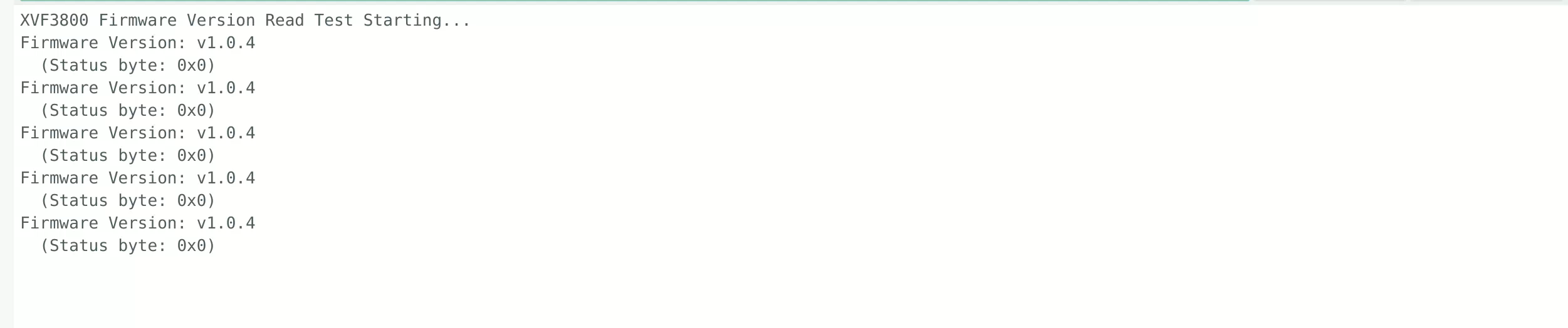
Expected Output
For an application example of controlling the ReSpeaker XVF3800 via the I2C interface, please refer to the Device Control section.
I2C Command List
ResID List
| Servicer Name | ResID | Hex | Description |
|---|---|---|---|
| PP Servicer (Post-Processing) | 17 | 0x11 | AGC, limiter, noise suppression, echo suppression |
| GPO Servicer (GPIO/LED/DOA) | 20 | 0x14 | GPO read/write, LED effect/color/speed/brightness, DOA |
| AEC Servicer (Acoustic Echo Cancellation) | 33 | 0x21 | AEC filter, beam, azimuth, RT60 |
| Audio Manager | 35 | 0x23 | Gain, I2S, channel selection, output routing |
| Application Servicer (System) | 48 | 0x30 | Version, reboot, config save, USB bit depth |
CmdID List
ResID = 48 — Application Servicer (System Control)
| Name | CmdID | Direction | Data Type | Values | Bytes | Description |
|---|---|---|---|---|---|---|
| VERSION | 0 | ro | uint8 | 3 | 3 | Firmware version (MAJOR, MINOR, PATCH) |
| BLD_MSG | 1 | ro | char | 50 | 50 | Build message (build config name) |
| BLD_HOST | 2 | ro | char | 30 | 30 | CI build host info |
| BLD_REPO_HASH | 3 | ro | char | 40 | 40 | GIT hash |
| BLD_MODIFIED | 4 | ro | char | 6 | 6 | Whether firmware was modified |
| BOOT_STATUS | 5 | ro | char | 3 | 3 | Boot mode (SPI/JTAG/FLASH) |
| TEST_CORE_BURN | 6 | rw | uint8 | 1 | 1 | Core stress test (reboots chip) |
| REBOOT | 7 | wo | uint8 | 1 | 1 | Reboot chip, restore default params |
| USB_BIT_DEPTH | 8 | rw | uint8 | 2 | 2 | USB bit depth (16/24/32), USB Mode only |
| SAVE_CONFIGURATION | 9 | wo | uint8 | 1 | 1 | Save current config to flash |
| CLEAR_CONFIGURATION | 10 | wo | uint8 | 1 | 1 | Clear config, restore defaults |
| AIC3104_HP_LEVEL | 11 | rw | uint8 | 1 | 1 | Headphone output level [0..9] |
| AIC3104_LINEOUT_LEVEL | 12 | rw | uint8 | 1 | 1 | Line output level [0..9] |
ResID = 20 — GPO Servicer (GPIO and LED Control)
| Name | CmdID | Direction | Data Type | Values | Bytes | Description |
|---|---|---|---|---|---|---|
| GPO_READ_VALUES | 0 | ro | uint8 | 5 | 5 | Read all GPO pin levels |
| GPO_WRITE_VALUE | 1 | wo | uint8 | 2 | 2 | Set specified GPO pin level |
| GPO_PORT_PIN_INDEX | 2 | rw | uint32 | 2 | 8 | GPO port/pin index |
| GPO_PIN_VAL | 3 | wo | uint8 | 3 | 3 | Write specified port pin value |
| GPO_PIN_ACTIVE_LEVEL | 4 | rw | uint32 | 1 | 4 | Active level (1=high, 0=low) |
| LED_EFFECT | 12 | rw | uint8 | 1 | 1 | LED effect (0=off 1=breathing 2=rainbow 3=solid 4=DOA 5=ring) |
| LED_BRIGHTNESS | 13 | rw | uint8 | 1 | 1 | LED brightness |
| LED_GAMMIFY | 14 | rw | uint8 | 1 | 1 | Gamma correction (0=off 1=on) |
| LED_SPEED | 15 | rw | uint8 | 1 | 1 | LED speed |
| LED_COLOR | 16 | rw | uint32 | 1 | 4 | LED color (RGB) |
| LED_DOA_COLOR | 17 | rw | uint32 | 2 | 8 | DOA mode color (base color + DOA color) |
| DOA_VALUE | 18 | ro | uint16 | 2 | 4 | DOA angle (0-359) + voice detection flag |
| LED_RING_COLOR | 19 | rw | uint32 | 12 | 48 | Ring mode per-LED color |
ResID = 33 — AEC Servicer (Acoustic Echo Cancellation)
| Name | CmdID | Direction | Data Type | Values | Bytes | Description |
|---|---|---|---|---|---|---|
| AEC_AECPATHCHANGE | 0 | ro | int32 | 1 | 4 | AEC path change detection (0,1) |
| AEC_HPFONOFF | 1 | rw | int32 | 1 | 4 | High-pass filter (0=off 1=70Hz 2=125Hz 3=150Hz 4=180Hz) |
| AEC_AECSILENCELEVEL | 2 | rw | float | 2 | 8 | Silence threshold [0.0..1.0] |
| AEC_AECCONVERGED | 3 | ro | int32 | 1 | 4 | AEC converged (0,1) |
| AEC_AECEMPHASISONOFF | 4 | rw | int32 | 1 | 4 | Pre/de-emphasis (0=off 1=on 2=on_eq) |
| AEC_FAR_EXTGAIN | 5 | rw | float | 1 | 4 | Far-end external gain (dB) |
| AEC_PCD_COUPLINGI | 6 | rw | float | 1 | 4 | PCD sensitivity [0.0..1.0] |
| AEC_PCD_MINTHR | 7 | rw | float | 1 | 4 | PCD min threshold [0.0..0.02] |
| AEC_PCD_MAXTHR | 8 | rw | float | 1 | 4 | PCD max threshold [0.025..0.2] |
| AEC_RT60 | 9 | ro | float | 1 | 4 | RT60 reverberation estimate [0.250..0.900] sec |
| AEC_ASROUTONOFF | 35 | rw | int32 | 1 | 4 | ASR output switch (0=residual 1=ASR processed) |
| AEC_ASROUTGAIN | 36 | rw | float | 1 | 4 | ASR output gain [0.0..1000.0] |
| AEC_FIXEDBEAMSONOFF | 37 | rw | int32 | 1 | 4 | Fixed beam mode switch (0,1) |
| AEC_FIXEDBEAMNOISETHR | 38 | rw | float | 2 | 8 | Fixed beam noise threshold [0.0..1.0] |
| SHF_BYPASS | 70 | rw | uint8 | 1 | 1 | AEC bypass |
| AEC_NUM_MICS | 71 | ro | int32 | 1 | 4 | Number of microphones |
| AEC_NUM_FARENDS | 72 | ro | int32 | 1 | 4 | Number of far-end references |
| AEC_MIC_ARRAY_TYPE | 73 | ro | int32 | 1 | 4 | Mic array type (1=linear 2=square) |
| AEC_MIC_ARRAY_GEO | 74 | ro | float | 12 | 48 | Mic array geometry (3D XYZ coordinates) |
| AEC_AZIMUTH_VALUES | 75 | ro | radians | 4 | 16 | Azimuth (beam1/2/free/auto) |
| TEST_AEC_DISABLE_CONTROL | 76 | wo | uint32 | 1 | 4 | Disable AEC control (test only) |
| AEC_CURRENT_IDLE_TIME | 77 | ro | uint32 | 1 | 4 | Current idle time (10ns tick) |
| AEC_MIN_IDLE_TIME | 78 | ro | uint32 | 1 | 4 | Min idle time (10ns tick) |
| AEC_RESET_MIN_IDLE_TIME | 79 | wo | uint32 | 1 | 4 | Reset min idle time |
| AEC_SPENERGY_VALUES | 80 | ro | float | 4 | 16 | Speech energy (beam1/2/free/auto) |
| AEC_FIXEDBEAMSAZIMUTH_VALUES | 81 | rw | radians | 2 | 8 | Fixed beam azimuth |
| AEC_FIXEDBEAMSELEVATION_VALUES | 82 | rw | radians | 2 | 8 | Fixed beam elevation |
| AEC_FIXEDBEAMSGATING | 83 | rw | uint8 | 1 | 1 | Fixed beam gating switch |
| SPECIAL_CMD_AEC_FAR_MIC_INDEX | 90 | wo | int32 | 2 | 8 | AEC filter read index (trigger command) |
| SPECIAL_CMD_AEC_FILTER_COEFF_START_OFFSET | 91 | rw | int32 | 1 | 4 | Filter coefficient start offset |
| SPECIAL_CMD_AEC_FILTER_COEFFS | 92 | rw | float | 15 | 60 | AEC filter coefficient read/write |
| SPECIAL_CMD_AEC_FILTER_LENGTH | 93 | ro | int32 | 1 | 4 | AEC filter length |
| AEC_FILTER_CMD_ABORT | 94 | wo | int32 | 1 | 4 | Abort filter read/write state machine |
ResID = 35 — Audio Manager (Audio Management)
| Name | CmdID | Direction | Data Type | Values | Bytes | Description |
|---|---|---|---|---|---|---|
| AUDIO_MGR_MIC_GAIN | 0 | rw | float | 1 | 4 | Microphone gain (before SHF) |
| AUDIO_MGR_REF_GAIN | 1 | rw | float | 1 | 4 | Reference gain (before SHF) |
| AUDIO_MGR_CURRENT_IDLE_TIME | 2 | ro | int32 | 1 | 4 | Current idle time (10ns tick) |
| AUDIO_MGR_MIN_IDLE_TIME | 3 | ro | int32 | 1 | 4 | Min idle time (10ns tick) |
| AUDIO_MGR_RESET_MIN_IDLE_TIME | 4 | wo | int32 | 1 | 4 | Reset min idle time |
| MAX_CONTROL_TIME | 5 | ro | int32 | 1 | 4 | Max control time |
| RESET_MAX_CONTROL_TIME | 6 | wo | int32 | 1 | 4 | Reset max control time |
| I2S_CURRENT_IDLE_TIME | 7 | ro | int32 | 1 | 4 | I2S current idle time |
| I2S_MIN_IDLE_TIME | 8 | ro | int32 | 1 | 4 | I2S min idle time |
| I2S_RESET_MIN_IDLE_TIME | 9 | wo | int32 | 1 | 4 | Reset I2S idle time |
| I2S_INPUT_PACKED | 10 | rw | uint8 | 1 | 1 | I2S/USB input packed mode |
| AUDIO_MGR_SELECTED_AZIMUTHS | 11 | ro | radians | 2 | 8 | Selected beam azimuth (process DOA + auto-select DOA) |
| AUDIO_MGR_SELECTED_CHANNELS | 12 | rw | uint8 | 2 | 2 | Selected output channels |
| AUDIO_MGR_OP_PACKED | 13 | rw | uint8 | 2 | 2 | L/R output packed status |
| AUDIO_MGR_OP_UPSAMPLE | 14 | rw | uint8 | 2 | 2 | L/R output upsampling status |
| AUDIO_MGR_OP_L | 15 | rw | uint8 | 2 | 2 | L channel category and source (= OP_L_PK0) |
| AUDIO_MGR_OP_L_PK0 | 16 | rw | uint8 | 2 | 2 | L channel packed source 0 |
| AUDIO_MGR_OP_L_PK1 | 17 | rw | uint8 | 2 | 2 | L channel packed source 1 |
| AUDIO_MGR_OP_L_PK2 | 18 | rw | uint8 | 2 | 2 | L channel packed source 2 |
| AUDIO_MGR_OP_R | 19 | rw | uint8 | 2 | 2 | R channel category and source (= OP_R_PK0) |
| AUDIO_MGR_OP_R_PK0 | 20 | rw | uint8 | 2 | 2 | R channel packed source 0 |
| AUDIO_MGR_OP_R_PK1 | 21 | rw | uint8 | 2 | 2 | R channel packed source 1 |
| AUDIO_MGR_OP_R_PK2 | 22 | rw | uint8 | 2 | 2 | R channel packed source 2 |
| AUDIO_MGR_OP_ALL | 23 | rw | uint8 | 12 | 12 | All L/R packed source settings |
| I2S_INACTIVE | 24 | ro | uint8 | 1 | 1 | I2S active (0=active 1=inactive) |
| AUDIO_MGR_FAR_END_DSP_ENABLE | 25 | rw | uint8 | 1 | 1 | Far-end DSP switch |
| AUDIO_MGR_SYS_DELAY | 26 | rw | int32 | 1 | 4 | Reference signal delay (samples) |
| I2S_DAC_DSP_ENABLE | 27 | rw | uint8 | 1 | 1 | DAC far-end DSP switch |
ResID = 17 — PP Servicer (Post-Processing: AGC/Noise/Echo)
| Name | CmdID | Direction | Data Type | Values | Bytes | Description |
|---|---|---|---|---|---|---|
| PP_AGCONOFF | 10 | rw | int32 | 1 | 4 | AGC switch (0,1) |
| PP_AGCMAXGAIN | 11 | rw | float | 1 | 4 | AGC max gain [1.0..1000.0] |
| PP_AGCDESIREDLEVEL | 12 | rw | float | 1 | 4 | AGC target power [1e-8..1.0] |
| PP_AGCGAIN | 13 | rw | float | 1 | 4 | AGC current gain [1.0..1000.0] |
| PP_AGCTIME | 14 | rw | float | 1 | 4 | AGC time constant [0.5..4.0] sec |
| PP_AGCFASTTIME | 15 | rw | float | 1 | 4 | AGC fast decay time [0.05..4.0] sec |
| PP_AGCALPHAFASTGAIN | 16 | rw | float | 1 | 4 | Fast mode gain threshold [0.0..1000.0] |
| PP_AGCALPHASLOW | 17 | rw | float | 1 | 4 | Slow memory parameter [0.0..1.0] |
| PP_AGCALPHAFAST | 18 | rw | float | 1 | 4 | Fast memory parameter [0.0..1.0] |
| PP_LIMITONOFF | 19 | rw | int32 | 1 | 4 | Limiter switch (0,1) |
| PP_LIMITPLIMIT | 20 | rw | float | 1 | 4 | Limiter max power [1e-8..1.0] |
| PP_MIN_NS | 21 | rw | float | 1 | 4 | Steady-state noise gain floor [0.0..1.0] |
| PP_MIN_NN | 22 | rw | float | 1 | 4 | Non-steady-state noise gain floor [0.0..1.0] |
| PP_ECHOONOFF | 23 | rw | int32 | 1 | 4 | Echo suppression switch (0,1) |
| PP_GAMMA_E | 24 | rw | float | 1 | 4 | Echo over-subtraction factor [0.0..2.0] |
| PP_GAMMA_ETAIL | 25 | rw | float | 1 | 4 | Tail echo over-subtraction factor [0.0..2.0] |
| PP_GAMMA_ENL | 26 | rw | float | 1 | 4 | Nonlinear echo over-subtraction factor [0.0..5.0] |
| PP_NLATTENONOFF | 27 | rw | int32 | 1 | 4 | Nonlinear echo attenuation switch (0,1) |
| PP_NLAEC_MODE | 28 | rw | int32 | 1 | 4 | Nonlinear AEC training mode (0=normal 1=training 2=training2) |
| PP_MGSCALE | 29 | rw | float | 3 | 12 | Min gain scale (max,min,cur) |
| PP_FMIN_SPEINDEX | 30 | rw | float | 1 | 4 | Double-talk frequency boundary [0.0..7999.0] |
| PP_DTSENSITIVE | 31 | rw | int32 | 1 | 4 | Double-talk sensitivity [0..5, 10..15] |
| PP_ATTNS_MODE | 32 | rw | int32 | 1 | 4 | Non-speech extra attenuation switch (0,1) |
| PP_ATTNS_NOMINAL | 33 | rw | float | 1 | 4 | Nominal speech attenuation [0.0..1.0] |
| PP_ATTNS_SLOPE | 34 | rw | float | 1 | 4 | Attenuation slope [0.0..5.0] |
| PP_CURRENT_IDLE_TIME | 70 | ro | uint32 | 1 | 4 | PP current idle time (10ns tick) |
| PP_MIN_IDLE_TIME | 71 | ro | uint32 | 1 | 4 | PP min idle time (10ns tick) |
| PP_RESET_MIN_IDLE_TIME | 72 | wo | uint32 | 1 | 4 | Reset PP min idle time |
| PP_NL_MODEL_CMD_ABORT | 94 | wo | int32 | 1 | 4 | Abort NL model read/write state machine |
| PP_EQUALIZATION_CMD_ABORT | 100 | wo | int32 | 1 | 4 | Abort equalizer read/write state machine |
Tech Support & Product Discussion
Thank you for choosing our products! We are here to provide you with different support to ensure that your experience with our products is as smooth as possible. We offer several communication channels to cater to different preferences and needs.