Arduino Cookbook: Onboard Peripherals (reTerminal E Series)
If you want to quickly preview project results or try the basic demo firmware before setting up a development environment, open the reTerminal E-Series Firmware Hub. You can choose a supported reTerminal E Series device and flash demo firmware directly from a browser.
- Arduino Cookbook: ePaper Display — rendering text, graphics, and images on the ePaper screen.
- Arduino Cookbook: RTC, Low Power, Audio & Touch — RTC time management, deep sleep / light sleep, I2S microphone recording, and capacitive touch drawing (E1003 only).
Introduction
The reTerminal E Series is more than just an ePaper screen — every model also exposes an onboard LED, a buzzer, three user buttons, an SHT4x temperature & humidity sensor, battery voltage monitoring, and a microSD card slot. This cookbook collects ready-to-flash Arduino examples for each of those peripherals, plus an end-to-end image pipeline that loads a JPEG / BMP / PNG file from the SD card, dithers it for the panel's palette, and renders it on the ePaper screen — one ready-made sketch per panel variant (E1001 BW, E1001 Gray4, E1002, E1003, E1004).
What this cookbook covers:
- LED control on GPIO6 (inverted logic).
- Buzzer alerts and music tones on GPIO45.
- Three user buttons (KEY0 / KEY1 / KEY2) with debounced state detection.
- SHT4x sensor over I²C (GPIO19 SDA / GPIO20 SCL) using the Sensirion library.
- Battery voltage monitoring through the ADC + enable-pin circuit.
- microSD card mount / detect / file listing on the shared SPI bus.
- Advanced example — SD-card image pipeline: pick any JPEG / BMP / PNG on the SD card, run it through one of five built-in dithering algorithms, and render it on the panel with configurable anchor, fit mode and scale.
Materials Required
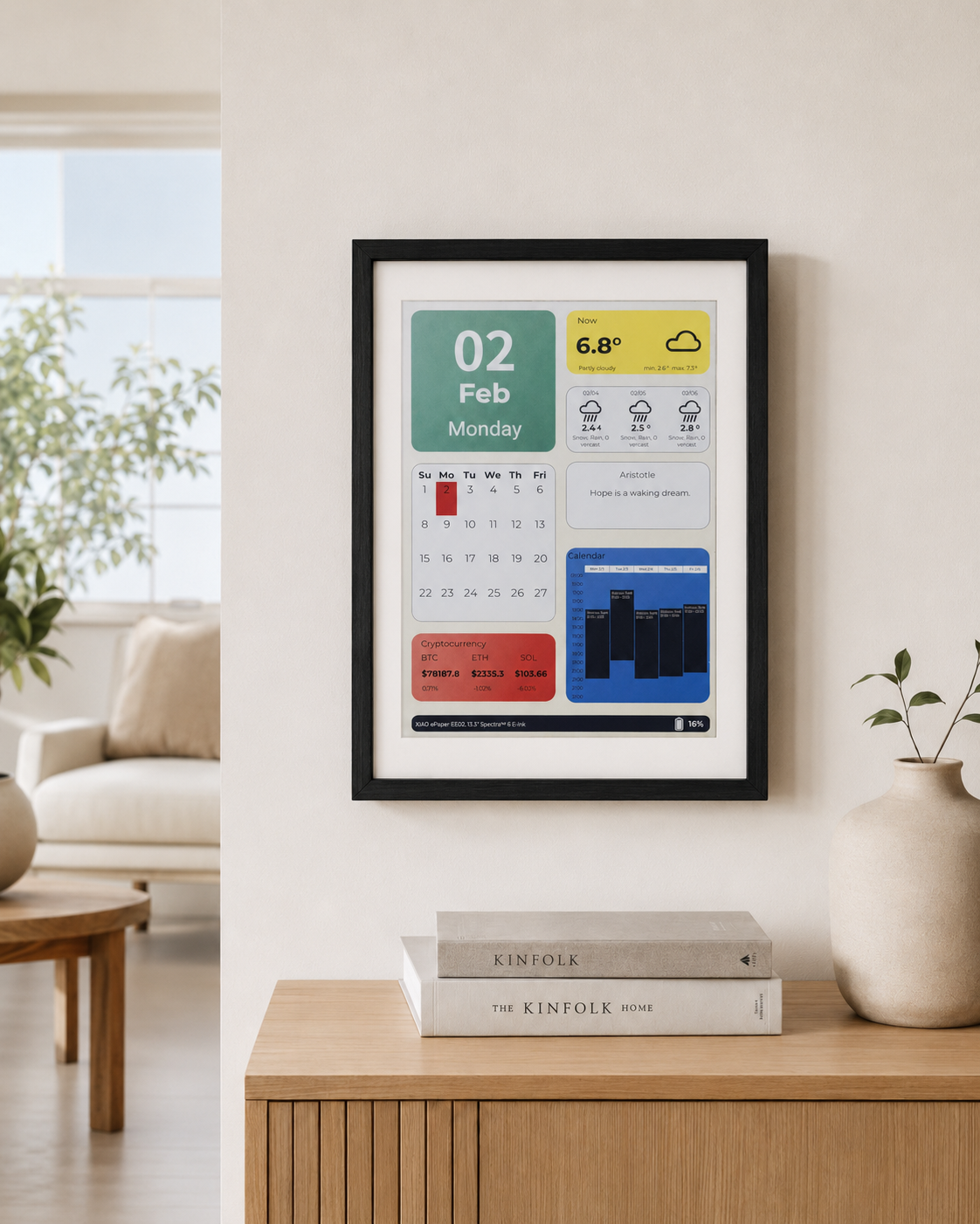
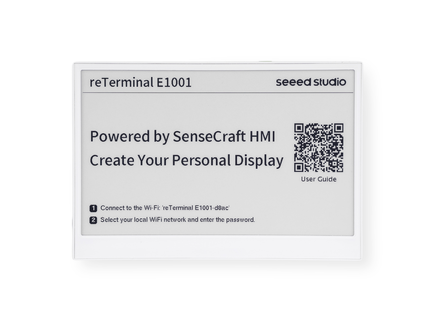
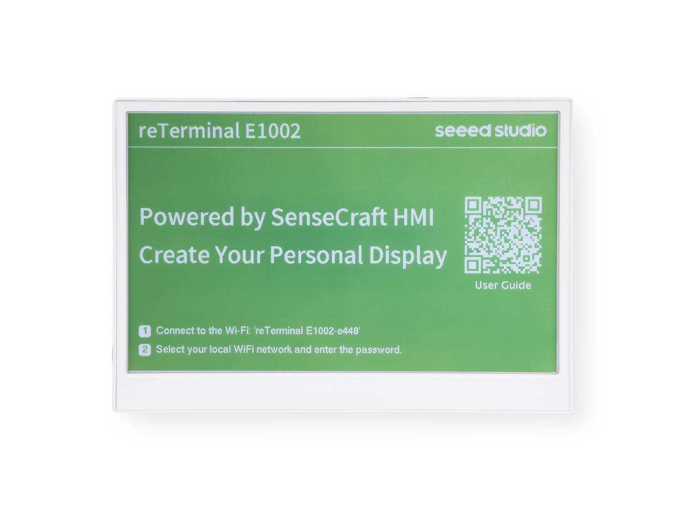
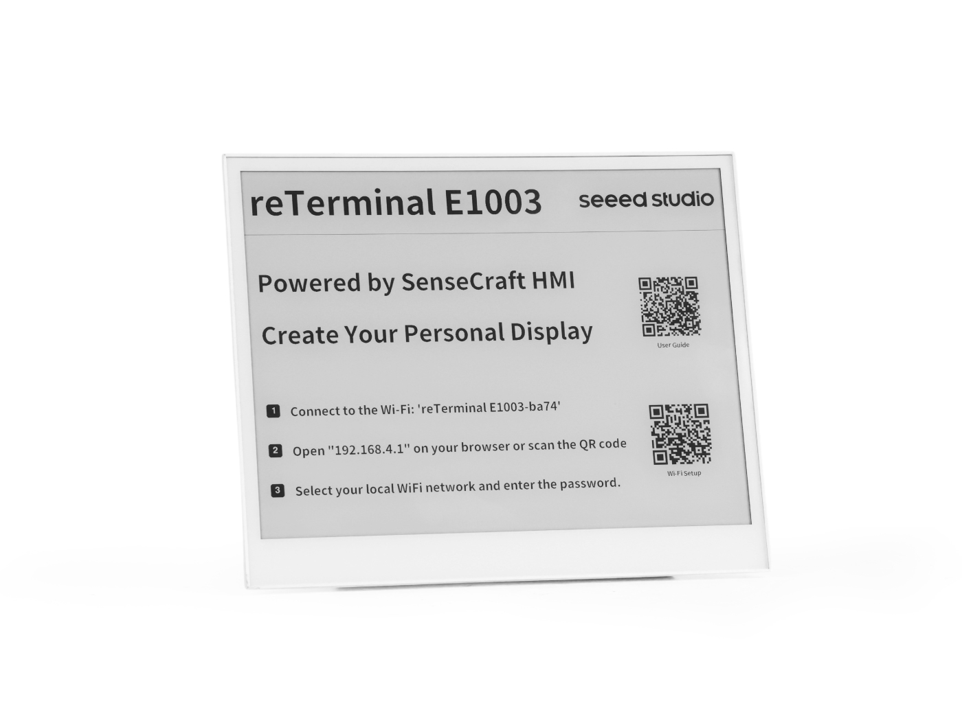
This cookbook applies to all four reTerminal E Series models. Pick whichever device you have on hand:
| reTerminal E1001 | reTerminal E1002 | reTerminal E1003 | reTerminal E1004 |
|---|---|---|---|
 |  |  |  |
Prerequisites
Before running any example below, you should already have:
- The Arduino IDE installed with the ESP32 board package and the XIAO_ESP32S3 board selected.
- A working USB-C data cable and the correct serial port selected.
- Verified that you can flash a basic sketch to the device — see the environment setup in Arduino Cookbook: ePaper Display if you haven't done this yet.
All sketches in this cookbook print debug information through Serial1 on pins GPIO44 (RX) / GPIO43 (TX) at 115200 baud. Open the Arduino Serial Monitor and select the matching port and baud rate to follow along.
LED Control
The reTerminal E Series has an onboard LED that can be controlled via GPIO. Note that the LED logic is inverted (LOW = ON, HIGH = OFF). The LED pin differs across models:
| Model | LED GPIO |
|---|---|
| E1001 / E1002 | GPIO6 |
| E1003 | GPIO16 |
| E1004 | GPIO48 |
- E1001 / E1002
- E1003
- E1004
// reTerminal E1001/E1002 - LED Control Example

#define SERIAL_RX 44
#define SERIAL_TX 43
#define LED_PIN 6  // GPIO6 - Onboard LED (inverted logic)

void setup() {
  Serial1.begin(115200, SERIAL_8N1, SERIAL_RX, SERIAL_TX);
  while (!Serial1) {
    delay(10);
  }

  Serial1.println("LED Control Example");

  // Configure LED pin
  pinMode(LED_PIN, OUTPUT);
}

void loop() {
  // Turn LED ON (LOW because it's inverted)
  digitalWrite(LED_PIN, LOW);
  Serial1.println("LED ON");
  delay(1000);

  // Turn LED OFF (HIGH because it's inverted)
  digitalWrite(LED_PIN, HIGH);
  Serial1.println("LED OFF");
  delay(1000);
}
// reTerminal E1003 - LED Control Example

#define SERIAL_RX 44
#define SERIAL_TX 43
#define LED_PIN 16  // GPIO16 - Onboard LED (inverted logic)

void setup() {
  Serial1.begin(115200, SERIAL_8N1, SERIAL_RX, SERIAL_TX);
  while (!Serial1) {
    delay(10);
  }

  Serial1.println("LED Control Example");

  // Configure LED pin
  pinMode(LED_PIN, OUTPUT);
}

void loop() {
  // Turn LED ON (LOW because it's inverted)
  digitalWrite(LED_PIN, LOW);
  Serial1.println("LED ON");
  delay(1000);

  // Turn LED OFF (HIGH because it's inverted)
  digitalWrite(LED_PIN, HIGH);
  Serial1.println("LED OFF");
  delay(1000);
}
// reTerminal E1004 - LED Control Example

#define SERIAL_RX 44
#define SERIAL_TX 43
#define LED_PIN 48  // GPIO48 - Onboard LED (inverted logic)

void setup() {
  Serial1.begin(115200, SERIAL_8N1, SERIAL_RX, SERIAL_TX);
  while (!Serial1) {
    delay(10);
  }

  Serial1.println("LED Control Example");

  // Configure LED pin
  pinMode(LED_PIN, OUTPUT);
}

void loop() {
  // Turn LED ON (LOW because it's inverted)
  digitalWrite(LED_PIN, LOW);
  Serial1.println("LED ON");
  delay(1000);

  // Turn LED OFF (HIGH because it's inverted)
  digitalWrite(LED_PIN, HIGH);
  Serial1.println("LED OFF");
  delay(1000);
}
Buzzer Control
The reTerminal E Series includes a buzzer on GPIO45 that can produce various tones and alert sounds.
// reTerminal E Series - Buzzer Control Example

#define SERIAL_RX 44
#define SERIAL_TX 43
#define BUZZER_PIN 45  // GPIO45 - Buzzer

void setup() {
  Serial1.begin(115200, SERIAL_8N1, SERIAL_RX, SERIAL_TX);
  while (!Serial1) {
    delay(10);
  }

  Serial1.println("Buzzer Control Example");
}

void loop() {
  Serial1.println("Simple beep");
  tone(BUZZER_PIN, 1000, 100);  // 1kHz for 100ms
  delay(1000);

  Serial1.println("Double beep");
  for (int i = 0; i < 2; i++) {
    tone(BUZZER_PIN, 2000, 50);  // 2kHz for 50ms
    delay(100);
  }
  delay(900);

  Serial1.println("Long beep");
  tone(BUZZER_PIN, 800, 500);  // 800Hz for 500ms
  delay(1500);

  Serial1.println("Alarm sound");
  for (int i = 0; i < 5; i++) {
    tone(BUZZER_PIN, 1500, 100);
    delay(100);
    tone(BUZZER_PIN, 1000, 100);
    delay(100);
  }
  delay(2000);
}
Buzzer with Tones
Click to expand the full Buzzer example code
#define SERIAL_RX 44
#define SERIAL_TX 43
#define BUZZER_PIN 45  // GPIO7 - Buzzer

// Reference:  This list was adapted from the table located here:
//    http://www.phy.mtu.edu/~suits/notefreqs.html
#define  NOTE_C0  16.35  //C0
#define  NOTE_Db0 17.32  //C#0/Db0
#define  NOTE_D0  18.35  //D0
#define  NOTE_Eb0 19.45 //D#0/Eb0
#define  NOTE_E0  20.6  //E0
#define  NOTE_F0  21.83  //F0
#define  NOTE_Gb0 23.12  //F#0/Gb0
#define  NOTE_G0  24.5  //G0
#define  NOTE_Ab0 25.96  //G#0/Ab0
#define  NOTE_A0  27.5  //A0
#define  NOTE_Bb0 29.14  //A#0/Bb0
#define  NOTE_B0  30.87  //B0
#define  NOTE_C1  32.7  //C1
#define  NOTE_Db1 34.65  //C#1/Db1
#define  NOTE_D1  36.71  //D1
#define  NOTE_Eb1 38.89  //D#1/Eb1
#define  NOTE_E1  41.2  //E1
#define  NOTE_F1  43.65  //F1
#define  NOTE_Gb1 46.25  //F#1/Gb1
#define  NOTE_G1  49 //G1
#define  NOTE_Ab1 51.91  //G#1/Ab1
#define  NOTE_A1  55  //A1
#define  NOTE_Bb1 58.27  //A#1/Bb1
#define  NOTE_B1  61.74  //B1
#define  NOTE_C2  65.41  //C2 (Middle C)
#define  NOTE_Db2 69.3  //C#2/Db2
#define  NOTE_D2  73.42  //D2
#define  NOTE_Eb2 77.78  //D#2/Eb2
#define  NOTE_E2  82.41  //E2
#define  NOTE_F2  87.31  //F2
#define  NOTE_Gb2 92.5  //F#2/Gb2
#define  NOTE_G2  98  //G2
#define  NOTE_Ab2 103.83  //G#2/Ab2
#define  NOTE_A2  110  //A2
#define  NOTE_Bb2 116.54  //A#2/Bb2
#define  NOTE_B2  123.47  //B2
#define  NOTE_C3  130.81  //C3
#define  NOTE_Db3 138.59  //C#3/Db3
#define  NOTE_D3  146.83  //D3
#define  NOTE_Eb3 155.56  //D#3/Eb3
#define  NOTE_E3  164.81  //E3
#define  NOTE_F3  174.61  //F3
#define  NOTE_Gb3 185  //F#3/Gb3
#define  NOTE_G3  196  //G3
#define  NOTE_Ab3 207.65  //G#3/Ab3
#define  NOTE_A3  220  //A3
#define  NOTE_Bb3 233.08  //A#3/Bb3
#define  NOTE_B3  246.94  //B3
#define  NOTE_C4  261.63  //C4
#define  NOTE_Db4 277.18  //C#4/Db4
#define  NOTE_D4  293.66  //D4
#define  NOTE_Eb4 311.13  //D#4/Eb4
#define  NOTE_E4  329.63  //E4
#define  NOTE_F4  349.23  //F4
#define  NOTE_Gb4 369.99  //F#4/Gb4
#define  NOTE_G4  392  //G4
#define  NOTE_Ab4 415.3  //G#4/Ab4
#define  NOTE_A4  440  //A4
#define  NOTE_Bb4 466.16  //A#4/Bb4
#define  NOTE_B4  493.88  //B4
#define  NOTE_C5  523.25  //C5
#define  NOTE_Db5 554.37  //C#5/Db5
#define  NOTE_D5  587.33  //D5
#define  NOTE_Eb5 622.25  //D#5/Eb5
#define  NOTE_E5  659.26  //E5
#define  NOTE_F5  698.46  //F5
#define  NOTE_Gb5 739.99  //F#5/Gb5
#define  NOTE_G5  783.99  //G5
#define  NOTE_Ab5 830.61  //G#5/Ab5
#define  NOTE_A5  880  //A5
#define  NOTE_Bb5 932.33  //A#5/Bb5
#define  NOTE_B5  987.77  //B5
#define  NOTE_C6  1046.5  //C6
#define  NOTE_Db6 1108.73  //C#6/Db6
#define  NOTE_D6  1174.66  //D6
#define  NOTE_Eb6 1244.51  //D#6/Eb6
#define  NOTE_E6  1318.51  //E6
#define  NOTE_F6  1396.91  //F6
#define  NOTE_Gb6 1479.98  //F#6/Gb6
#define  NOTE_G6  1567.98  //G6
#define  NOTE_Ab6 1661.22  //G#6/Ab6
#define  NOTE_A6  1760  //A6
#define  NOTE_Bb6 1864.66  //A#6/Bb6
#define  NOTE_B6  1975.53  //B6
#define  NOTE_C7  2093  //C7
#define  NOTE_Db7 2217.46  //C#7/Db7
#define  NOTE_D7  2349.32  //D7
#define  NOTE_Eb7 2489.02  //D#7/Eb7
#define  NOTE_E7  2637.02  //E7
#define  NOTE_F7  2793.83  //F7
#define  NOTE_Gb7 2959.96  //F#7/Gb7
#define  NOTE_G7  3135.96  //G7
#define  NOTE_Ab7 3322.44  //G#7/Ab7
#define  NOTE_A7  3520  //A7
#define  NOTE_Bb7 3729.31  //A#7/Bb7
#define  NOTE_B7  3951.07  //B7
#define  NOTE_C8  4186.01  //C8
#define  NOTE_Db8 4434.92  //C#8/Db8
#define  NOTE_D8  4698.64  //D8
#define  NOTE_Eb8 4978.03  //D#8/Eb8

void buzzer_tone (float noteFrequency, long noteDuration, int silentDuration){
  if(silentDuration==0) {silentDuration=1;}

  tone(BUZZER_PIN, noteFrequency, noteDuration);
  delay(noteDuration);     // milliseconds
  noTone(BUZZER_PIN);      // stop the tone

  delay(silentDuration);
}

void setup() {
  Serial1.begin(115200, SERIAL_8N1, SERIAL_RX, SERIAL_TX);
  while (!Serial1) {
    delay(10);
  }

  Serial1.println("Buzzer Control Example");

  // Configure buzzer pin
  pinMode(BUZZER_PIN, OUTPUT);
}

void loop() {
  buzzer_tone(NOTE_C5, 80, 20);
  buzzer_tone(NOTE_E5, 80, 20);
  buzzer_tone(NOTE_G5, 80, 20);
  buzzer_tone(NOTE_C6, 150, 0);
  delay(30000);
}
Buzzer Functions:
digitalWrite(): Simple ON/OFF control for basic beepstone(pin, frequency, duration): Generate specific frequencies for melodies or alertsnoTone(pin): Stop tone generation
Common Alert Patterns:
- Single beep: Confirmation
- Double beep: Warning
- Triple beep: Error
- Continuous: Critical alert
User Buttons
The reTerminal E Series features three user-programmable buttons that can be used for various control purposes. This section demonstrates how to read button states and respond to button presses using Arduino.
The reTerminal E Series has three buttons connected to the ESP32-S3 via KEY0 (GPIO3), KEY1 (GPIO4), and KEY2 (GPIO5). All buttons are active-low, meaning they read LOW when pressed and HIGH when released.
The physical layout and function of these buttons differ between models:
| Key | E1001 / E1002 / E1003 | E1004 |
|---|---|---|
| KEY0 (GPIO3) | Right button (Green Button) | Right direction button (front) |
| KEY1 (GPIO4) | Middle button | Left direction button (front) |
| KEY2 (GPIO5) | Left button | Refresh button (front-left) |
E1004 has buttons on both the front and back of the device. The KEY0–KEY2 connections listed above correspond to the buttons on the front panel.
Basic Button Reading Example
This example demonstrates how to detect button presses and print messages to the serial monitor.
// reTerminal E Series - Button Test
// Based on hardware schematic

// Define button pins according to schematic
const int BUTTON_KEY0 = 3;   // KEY0 - GPIO3
const int BUTTON_KEY1 = 4;   // KEY1 - GPIO4
const int BUTTON_KEY2 = 5;   // KEY2 - GPIO5

// Button state variables
bool lastKey0State = HIGH;
bool lastKey1State = HIGH;
bool lastKey2State = HIGH;

void setup() {
  // Initialize serial communication
  Serial1.begin(115200, SERIAL_8N1, 44, 43);
  while (!Serial1) {
    delay(10); // Wait for serial port to connect
  }

  Serial1.println("=================================");
  Serial1.println("reTerminal E Series - Button Test");
  Serial1.println("=================================");
  Serial1.println("Press any button to see output");
  Serial1.println();

  // Configure button pins as inputs
  // Hardware already has pull-up resistors, so use INPUT mode
  pinMode(BUTTON_KEY0, INPUT);
  pinMode(BUTTON_KEY1, INPUT);
  pinMode(BUTTON_KEY2, INPUT);

  // Read initial states
  lastKey0State = digitalRead(BUTTON_KEY0);
  lastKey1State = digitalRead(BUTTON_KEY1);
  lastKey2State = digitalRead(BUTTON_KEY2);

  Serial1.println("Setup complete. Ready to detect button presses...");
}

void loop() {
  // Read current button states
  bool key0State = digitalRead(BUTTON_KEY0);
  bool key1State = digitalRead(BUTTON_KEY1);
  bool key2State = digitalRead(BUTTON_KEY2);

  // Check KEY0
  if (key0State != lastKey0State) {
    if (key0State == LOW) {
      Serial1.println("KEY0 (GPIO3) pressed!");
    } else {
      Serial1.println("KEY0 (GPIO3) released!");
    }
    lastKey0State = key0State;
    delay(50); // Debounce delay
  }

  // Check KEY1
  if (key1State != lastKey1State) {
    if (key1State == LOW) {
      Serial1.println("KEY1 (GPIO4) pressed!");
    } else {
      Serial1.println("KEY1 (GPIO4) released!");
    }
    lastKey1State = key1State;
    delay(50); // Debounce delay
  }

  // Check KEY2
  if (key2State != lastKey2State) {
    if (key2State == LOW) {
      Serial1.println("KEY2 (GPIO5) pressed!");
    } else {
      Serial1.println("KEY2 (GPIO5) released!");
    }
    lastKey2State = key2State;
    delay(50); // Debounce delay
  }

  delay(10); // Small delay to prevent excessive CPU usage
}
How the Code Works:
-
Pin Definition: We define constants for each button's GPIO pin number.
-
Pin Configuration: In
setup(), we configure each button pin asINPUT. -
Button Detection: In
loop(), we continuously check each button's state usingdigitalRead(). When a button is pressed, the pin reads LOW. -
Debouncing: A simple 200ms delay after each button press prevents multiple detections from a single press due to mechanical bounce.
-
Serial Output: Each button press triggers a message to the serial monitor for debugging and verification.
Step 1. Upload the code to your reTerminal E Series device.
Step 2. Open the Serial Monitor in Arduino IDE (Tools > Serial Monitor).
Step 3. Set the baud rate to 115200.
Step 4. Press each button and observe the output in the Serial Monitor.
Expected output when pressing buttons:
=================================
reTerminal E Series - Button Test
=================================
Press any button to see output

KEY0 (GPIO3) pressed!
KEY0 (GPIO3) released!
KEY1 (GPIO4) pressed!
KEY1 (GPIO4) released!
KEY2 (GPIO5) pressed!
KEY2 (GPIO5) released!
Environmental Sensor (SHT4x)
The reTerminal E Series includes an integrated SHT4x temperature and humidity sensor connected via I2C.
Installing Required Libraries
Install two libraries via Arduino Library Manager (Tools > Manage Libraries...):
- Search and install "Sensirion I2C SHT4x"
- Search and install "Sensirion Core" (dependency)
Basic Temperature and Humidity Example
// reTerminal E Series - SHT40 Temperature & Humidity Sensor Example

#include <Wire.h>
#include <SensirionI2cSht4x.h>

// Serial configuration for reTerminal E Series
#define SERIAL_RX 44
#define SERIAL_TX 43

// I2C pins for reTerminal E Series
#define I2C_SDA 19
#define I2C_SCL 20

// Create sensor object
SensirionI2cSht4x sht4x;

void setup() {
    // Initialize Serial1 for reTerminal E Series
    Serial1.begin(115200, SERIAL_8N1, SERIAL_RX, SERIAL_TX);
    while (!Serial1) {
        delay(10);
    }

    Serial1.println("SHT4x Basic Example");

    // Initialize I2C with custom pins
    Wire.begin(I2C_SDA, I2C_SCL);

    uint16_t error;
    char errorMessage[256];

    // Initialize the sensor
    sht4x.begin(Wire, 0x44);

    // Read and print serial number
    uint32_t serialNumber;
    error = sht4x.serialNumber(serialNumber);

    if (error) {
        Serial1.print("Error trying to execute serialNumber(): ");
        errorToString(error, errorMessage, 256);
        Serial1.println(errorMessage);
    } else {
        Serial1.print("Serial Number: ");
        Serial1.println(serialNumber);
        Serial1.println();
    }
}

void loop() {
    uint16_t error;
    char errorMessage[256];

    delay(5000);  // Wait 5 seconds between measurements

    float temperature;
    float humidity;

    // Measure temperature and humidity with high precision
    error = sht4x.measureHighPrecision(temperature, humidity);

    if (error) {
        Serial1.print("Error trying to execute measureHighPrecision(): ");
        errorToString(error, errorMessage, 256);
        Serial1.println(errorMessage);
    } else {
        Serial1.print("Temperature: ");
        Serial1.print(temperature);
        Serial1.print("°C\t");
        Serial1.print("Humidity: ");
        Serial1.print(humidity);
        Serial1.println("%");
    }
}
Setup Function:
- Serial Initialization: Uses
Serial1with pins 44 (RX) and 43 (TX) specific to reTerminal E Series - I2C Initialization: Configures I2C with pins 19 (SDA) and 20 (SCL)
- Sensor Initialization: Calls
sht4x.begin(Wire, 0x44)to initialize the SHT4x sensor at address 0x44 - Serial Number Reading: Reads and displays the sensor's unique serial number for verification
Loop Function:
- Delay: Waits 5 seconds between measurements to avoid oversampling
- Measurement: Uses
measureHighPrecision()for accurate readings (takes ~8.3ms) - Error Handling: Checks for errors and converts them to readable messages using
errorToString() - Display Results: Prints temperature in Celsius and relative humidity percentage
Expected Output
SHT4x Basic Example
Serial Number: 331937553

Temperature: 27.39°C Humidity: 53.68%
Temperature: 27.40°C Humidity: 53.51%
Temperature: 27.38°C Humidity: 53.37%
Battery Management System
The reTerminal E Series includes battery voltage monitoring capability through an ADC pin with voltage divider circuit.
The BATTERY_ENABLE_PIN on reTerminal E1003 differs from E1001/E1002/E1004.
- E1001/E1002/E1004: BATTERY_ENABLE_PIN → GPIO21
- E1003: BATTERY_ENABLE_PIN → IO40 Please update your code accordingly when porting examples between different reTerminal E10xx models.
Simple Battery Voltage Monitoring
// reTerminal E Series - Simple Battery Voltage Reading

// Serial configuration
#define SERIAL_RX 44
#define SERIAL_TX 43

// Battery monitoring pins
#define BATTERY_ADC_PIN 1      // GPIO1 - Battery voltage ADC
#define BATTERY_ENABLE_PIN 21  // GPIO21 - Battery monitoring enable

void setup() {
  // Initialize serial
  Serial1.begin(115200, SERIAL_8N1, SERIAL_RX, SERIAL_TX);
  while (!Serial1) {
    delay(10);
  }

  Serial1.println("Battery Voltage Monitor");

  // Configure battery monitoring enable pin
  pinMode(BATTERY_ENABLE_PIN, OUTPUT);
  digitalWrite(BATTERY_ENABLE_PIN, HIGH);  // Enable battery monitoring

  // Configure ADC
  analogReadResolution(12);  // 12-bit resolution
  analogSetPinAttenuation(BATTERY_ADC_PIN, ADC_11db);

  delay(100);  // Allow circuit to stabilize
}

void loop() {
  // Enable battery monitoring
  digitalWrite(BATTERY_ENABLE_PIN, HIGH);
  delay(5);

  // Read voltage in millivolts
  int mv = analogReadMilliVolts(BATTERY_ADC_PIN);

  // Disable battery monitoring
  digitalWrite(BATTERY_ENABLE_PIN, LOW);

  // Calculate actual battery voltage (2x due to voltage divider)
  float batteryVoltage = (mv / 1000.0) * 2;

  // Print voltage
  Serial1.print("Battery: ");
  Serial1.print(batteryVoltage, 2);
  Serial1.println(" V");

  delay(2000);
}
Code Explanation:
- GPIO1 reads the divided battery voltage through ADC
- GPIO21 enables the battery monitoring circuit
- The actual battery voltage is twice the measured voltage due to the voltage divider
- For a fully charged LiPo battery, expect around 4.2V
- When battery is low, voltage drops to around 3.3V
Expected Output
Battery Voltage Monitor

Battery: 4.18 V
Battery: 4.19 V
Battery: 4.18 V
Using the MicroSD Card
For applications requiring additional storage, such as a digital photo frame or data logging, the reTerminal E Series includes a MicroSD card slot.
Insert a microSD card if you plan to use the device as a digital photo frame or need additional storage.

The reTerminal E Series only supports MicroSD cards up to 64GB formatted with the Fat32 file system.
Basic SD Card Operations: Listing Files
This example demonstrates how to initialize the SD card, detect when it is inserted or removed, and list all the files and directories in its root. The SD card power enable pin (SD_EN_PIN) differs across models:
| Model | SD_EN_PIN | GPIO |
|---|---|---|
| E1001 / E1002 / E1004 | 16 | GPIO16 |
| E1003 | 39 | GPIO39 |
All other SD card pins (DET, CS, MOSI, MISO, SCK) are the same across models. Select the tab for your device and copy the code into your Arduino IDE sketch.
- E1001 / E1002 / E1004
- E1003
Click to expand the full SD Card example code
#include <SD.h>
#include <SPI.h>

// SD Card Pin Definitions
#define SD_EN_PIN   16  // Power enable for the SD card slot
#define SD_DET_PIN  15  // Card detection pin
#define SD_CS_PIN   14  // Chip Select for the SD card
#define SD_MOSI_PIN 9   // Shared with ePaper Display
#define SD_MISO_PIN 8
#define SD_SCK_PIN  7   // Shared with ePaper Display

// Serial configuration for reTerminal E Series
#define SERIAL_RX 44
#define SERIAL_TX 43

// Use the HSPI bus for the SD card to avoid conflict with other peripherals
SPIClass spiSD(HSPI);

// Global variables to track SD card state
bool sdMounted = false;
bool lastCardPresent = false;
unsigned long lastCheckMs = 0;
const unsigned long checkIntervalMs = 1000; // Check for card changes every second

// Checks if a card is physically inserted.
// The detection pin is LOW when a card is present.
bool isCardInserted() {
  return digitalRead(SD_DET_PIN) == LOW;
}

// Helper function to print indentation for directory listing
void printIndent(uint8_t level) {
  for (uint8_t i = 0; i < level; ++i) {
    Serial1.print("  ");
  }
}

// Recursively lists files and directories
void listDir(File dir, uint8_t level) {
  while (true) {
    File entry = dir.openNextFile();
    if (!entry) {
      // No more entries in this directory
      break;
    }

    printIndent(level);
    if (entry.isDirectory()) {
      Serial1.print("[DIR]  ");
      Serial1.println(entry.name());
      // Recurse into the subdirectory
      listDir(entry, level + 1);
    } else {
      // It's a file, print its name and size
      Serial1.print("[FILE] ");
      Serial1.print(entry.name());
      Serial1.print("  ");
      Serial1.print(entry.size());
      Serial1.println(" bytes");
    }
    entry.close();
  }
}

// Opens the root directory and starts the listing process
void listRoot() {
  File root = SD.open("/");
  if (!root) {
    Serial1.println("[SD] Failed to open root directory.");
    return;
  }
  if (!root.isDirectory()) {
    Serial1.println("[SD] Root is not a directory.");
    root.close();
    return;
  }
  Serial1.println("[SD] Listing files in /");
  listDir(root, 0);
  root.close();
}

// Initializes the SPI bus and mounts the SD card
bool mountSD() {
  // Enable power to the SD card slot
  pinMode(SD_EN_PIN, OUTPUT);
  digitalWrite(SD_EN_PIN, HIGH);
  delay(5);

  // Initialize the HSPI bus with the correct pins for the SD card
  spiSD.end(); // Guard against repeated begin calls
  spiSD.begin(SD_SCK_PIN, SD_MISO_PIN, SD_MOSI_PIN, SD_CS_PIN);

  // Attempt to mount the SD card file system
  if (!SD.begin(SD_CS_PIN, spiSD)) {
    Serial1.println("[SD] MicroSD initialization failed. Check card formatting.");
    return false;
  }
  Serial1.println("[SD] MicroSD mounted successfully.");
  return true;
}

// Unmounts the SD card by releasing the SPI bus
void unmountSD() {
  SD.end();
  spiSD.end();
  Serial1.println("[SD] MicroSD unmounted.");
}

void setup() {
  // Start the secondary serial port for output
  Serial1.begin(115200, SERIAL_8N1, SERIAL_RX, SERIAL_TX);
  while (!Serial1) {
    delay(10); // Wait for Serial1 to be ready
  }

  // Set up the card detection pin with an internal pull-up resistor
  pinMode(SD_DET_PIN, INPUT_PULLUP);
  // Set up the power enable pin
  pinMode(SD_EN_PIN, OUTPUT);
  digitalWrite(SD_EN_PIN, HIGH);

  // Check for a card at startup
  lastCardPresent = isCardInserted();
  if (lastCardPresent) {
    sdMounted = mountSD();
    if (sdMounted) {
      listRoot(); // If mounted, list files
    }
  } else {
    Serial1.println("[SD] No card detected at startup. Please insert a card.");
  }
}

void loop() {
  // Periodically check for card insertion or removal without blocking the loop
  unsigned long now = millis();
  if (now - lastCheckMs >= checkIntervalMs) {
    lastCheckMs = now;

    bool present = isCardInserted();
    if (present != lastCardPresent) {
      lastCardPresent = present; // Update the state

      if (present) {
        Serial1.println("\n[SD] Card inserted.");
        if (!sdMounted) {
          sdMounted = mountSD();
        }
        if (sdMounted) {
          listRoot(); // List files upon insertion
        }
      } else {
        Serial1.println("\n[SD] Card removed.");
        if (sdMounted) {
          unmountSD();
          sdMounted = false;
        }
      }
    }
  }
  // You can place other non-blocking code here
}
Click to expand the full SD Card example code
#include <SD.h>
#include <SPI.h>

// SD Card Pin Definitions
#define SD_EN_PIN   39  // Power enable for the SD card slot (E1003)
#define SD_DET_PIN  15  // Card detection pin
#define SD_CS_PIN   14  // Chip Select for the SD card
#define SD_MOSI_PIN 9   // Shared with ePaper Display
#define SD_MISO_PIN 8
#define SD_SCK_PIN  7   // Shared with ePaper Display

// Serial configuration for reTerminal E Series
#define SERIAL_RX 44
#define SERIAL_TX 43

// Use the HSPI bus for the SD card to avoid conflict with other peripherals
SPIClass spiSD(HSPI);

// Global variables to track SD card state
bool sdMounted = false;
bool lastCardPresent = false;
unsigned long lastCheckMs = 0;
const unsigned long checkIntervalMs = 1000; // Check for card changes every second

// Checks if a card is physically inserted.
// The detection pin is LOW when a card is present.
bool isCardInserted() {
  return digitalRead(SD_DET_PIN) == LOW;
}

// Helper function to print indentation for directory listing
void printIndent(uint8_t level) {
  for (uint8_t i = 0; i < level; ++i) {
    Serial1.print("  ");
  }
}

// Recursively lists files and directories
void listDir(File dir, uint8_t level) {
  while (true) {
    File entry = dir.openNextFile();
    if (!entry) {
      // No more entries in this directory
      break;
    }

    printIndent(level);
    if (entry.isDirectory()) {
      Serial1.print("[DIR]  ");
      Serial1.println(entry.name());
      // Recurse into the subdirectory
      listDir(entry, level + 1);
    } else {
      // It's a file, print its name and size
      Serial1.print("[FILE] ");
      Serial1.print(entry.name());
      Serial1.print("  ");
      Serial1.print(entry.size());
      Serial1.println(" bytes");
    }
    entry.close();
  }
}

// Opens the root directory and starts the listing process
void listRoot() {
  File root = SD.open("/");
  if (!root) {
    Serial1.println("[SD] Failed to open root directory.");
    return;
  }
  if (!root.isDirectory()) {
    Serial1.println("[SD] Root is not a directory.");
    root.close();
    return;
  }
  Serial1.println("[SD] Listing files in /");
  listDir(root, 0);
  root.close();
}

// Initializes the SPI bus and mounts the SD card
bool mountSD() {
  // Enable power to the SD card slot
  pinMode(SD_EN_PIN, OUTPUT);
  digitalWrite(SD_EN_PIN, HIGH);
  delay(5);

  // Initialize the HSPI bus with the correct pins for the SD card
  spiSD.end(); // Guard against repeated begin calls
  spiSD.begin(SD_SCK_PIN, SD_MISO_PIN, SD_MOSI_PIN, SD_CS_PIN);

  // Attempt to mount the SD card file system
  if (!SD.begin(SD_CS_PIN, spiSD)) {
    Serial1.println("[SD] MicroSD initialization failed. Check card formatting.");
    return false;
  }
  Serial1.println("[SD] MicroSD mounted successfully.");
  return true;
}

// Unmounts the SD card by releasing the SPI bus
void unmountSD() {
  SD.end();
  spiSD.end();
  Serial1.println("[SD] MicroSD unmounted.");
}

void setup() {
  // Start the secondary serial port for output
  Serial1.begin(115200, SERIAL_8N1, SERIAL_RX, SERIAL_TX);
  while (!Serial1) {
    delay(10); // Wait for Serial1 to be ready
  }

  // Set up the card detection pin with an internal pull-up resistor
  pinMode(SD_DET_PIN, INPUT_PULLUP);
  // Set up the power enable pin
  pinMode(SD_EN_PIN, OUTPUT);
  digitalWrite(SD_EN_PIN, HIGH);

  // Check for a card at startup
  lastCardPresent = isCardInserted();
  if (lastCardPresent) {
    sdMounted = mountSD();
    if (sdMounted) {
      listRoot(); // If mounted, list files
    }
  } else {
    Serial1.println("[SD] No card detected at startup. Please insert a card.");
  }
}

void loop() {
  // Periodically check for card insertion or removal without blocking the loop
  unsigned long now = millis();
  if (now - lastCheckMs >= checkIntervalMs) {
    lastCheckMs = now;

    bool present = isCardInserted();
    if (present != lastCardPresent) {
      lastCardPresent = present; // Update the state

      if (present) {
        Serial1.println("\n[SD] Card inserted.");
        if (!sdMounted) {
          sdMounted = mountSD();
        }
        if (sdMounted) {
          listRoot(); // List files upon insertion
        }
      } else {
        Serial1.println("\n[SD] Card removed.");
        if (sdMounted) {
          unmountSD();
          sdMounted = false;
        }
      }
    }
  }
  // You can place other non-blocking code here
}
Code Explanation
- Pin Definitions: The code begins by defining the GPIO pins used for the MicroSD card slot. Note that the SPI pins (
MOSI,SCK) are shared with the e-paper display, but a separate Chip Select (SD_CS_PIN) and a dedicated SPI instance (spiSD) ensure they can be used independently. - SPI Initialization: We instantiate a new SPI object,
spiSD(HSPI), to use the ESP32's second hardware SPI controller (HSPI). This is best practice to avoid conflicts with other SPI devices. - Card Detection: The
isCardInserted()function reads theSD_DET_PIN. On the reTerminal hardware, this pin is pulled LOW when a card is present. - Mount/Unmount: The
mountSD()function enables power to the card, configures the HSPI bus with the correct pins, and callsSD.begin()to initialize the file system.unmountSD()releases the resources. - File Listing:
listRoot()opens the root directory (/), andlistDir()is a recursive function that traverses the file system, printing the names of all files and directories. setup(): InitializesSerial1for output, configures the card detection pin, and performs an initial check to see if a card is already inserted when the device powers on.loop(): Instead of constantly checking the card, the code uses a non-blocking timer (millis()) to check for a change in the card's status once per second. If a change is detected (card inserted or removed), it mounts or unmounts the card and prints the status to the serial monitor.
Expected Results
- Upload the code to your reTerminal.
- Open the Arduino IDE's Serial Monitor (Tools > Serial Monitor).
- Make sure the baud rate is set to 115200.
You will see output corresponding to the following actions:
- On startup with no card: The monitor will print
[SD] No card detected at startup... - When you insert a card: The monitor will print
[SD] Card inserted., followed by a full listing of all files and directories on the card. - When you remove the card: The monitor will print
[SD] Card removed.
[FILE] live.0.shadowIndexGroups  6 bytes
[FILE] reverseStore.updates  1 bytes
[DIR]  journals.repair
[FILE] Cab.modified  0 bytes
[FILE] live.1.indexPositionTable  8192 bytes
[FILE] live.1.indexTermIds  8192 bytes
[FILE] tmp.spotlight.loc  2143 bytes
[FILE] live.1.shadowIndexTermIds  624 bytes
[FILE] live.1.indexArrays  65536 bytes
[FILE] live.1.shadowIndexArrays  65536 bytes
[FILE] live.1.indexHead  4096 bytes
[FILE] live.1.indexPostings  4096 bytes
Advanced Example: SD Card → ePaper Image Pipeline
This is the flagship example for the reTerminal E Series. It loads a JPEG / BMP / PNG file from the microSD card, runs it through a configurable dithering pipeline, and renders the result on the ePaper panel — with knobs for dithering algorithm, brightness, anchor position and fit / scale. The same code structure works on all four panel variants; what changes per model is only the output color depth (1-bit BW, 2-bit Gray4, 4-bit Gray16, or 6-color E6).
Five ready-to-flash sketches ship with the Seeed_GFX library — pick the one that matches your hardware:
Example Index
| Device | Example sketch | Panel resolution | Output palette |
|---|---|---|---|
| reTerminal E1001 (BW) | reTerminal_E1001_SDcard_BW | 800 × 480 | 1-bit black / white |
| reTerminal E1001 (Gray4) | reTerminal_E1001_SDcard_Gray4 | 800 × 480 | 2-bit 4-level grayscale |
| reTerminal E1002 | reTerminal_E1002_SDcard_Color6 | 800 × 480 | 6-color (B / W / R / Y / G / B) |
| reTerminal E1003 | reTerminal_E1003_SDcard_Gray16 | 1872 × 1404 | 4-bit 16-level grayscale |
| reTerminal E1004 | reTerminal_E1004_SDcard_Color6 | 1200 × 1600 | 6-color (B / W / R / Y / G / B) |
All five sketches live under Seeed_GFX/examples/ePaper/reTerminal_SDcard_Bitmap/. Each folder is fully self-contained — no extra libraries to install, just open and flash.
What the Pipeline Does
Image Processing Pipeline: microSD to ePaper
- Decode — file format is detected by magic bytes (
FF D8,BM, or89 50 4E 47). A misleading extension is auto-corrected and a warning is logged. - Resize (optional) — nearest-neighbor downscale based on
DISPLAY_FIT/DISPLAY_SCALE. - Dither — one of five algorithms quantises 24-bit RGB into the panel's tiny palette (2 / 4 / 6 / 16 levels).
- Push — the quantised buffer is written into the ePaper Sprite at the anchor position, then
epaper.update()clocks it out to the panel.
Step 1 — Open the Example for Your Model
In the Arduino IDE: File → Examples → Seeed_GFX → ePaper → reTerminal_SDcard_Bitmap → (pick your model).
- E1001 BW
- E1001 Gray4
- E1002
- E1003
- E1004
reTerminal_SDcard_Bitmap/
└── reTerminal_E1001_SDcard_BW/
    ├── reTerminal_E1001_SDcard_BW.ino   ← config + setup() + loop()
    ├── dither.{h,cpp}                   ← BW dither algorithms
    ├── image_loader.{h,cpp}             ← JPEG / BMP / PNG decoder
    ├── pngle.{h,c} + miniz.{h,c}        ← PNG backend (MIT, vendored)
    └── driver.h                         ← selects Setup520 (UC8179, 800x480)
reTerminal_SDcard_Bitmap/
└── reTerminal_E1001_SDcard_Gray4/
    ├── reTerminal_E1001_SDcard_Gray4.ino
    ├── dither.{h,cpp}                   ← Gray4 dither algorithms
    ├── image_loader.{h,cpp}
    ├── pngle.{h,c} + miniz.{h,c}
    └── driver.h                         ← Setup520 + initGrayMode(4)
reTerminal_SDcard_Bitmap/
└── reTerminal_E1002_SDcard_Color6/
    ├── reTerminal_E1002_SDcard_Color6.ino
    ├── dither.{h,cpp}                   ← 6-color dither algorithms
    ├── image_loader.{h,cpp}
    ├── pngle.{h,c} + miniz.{h,c}
    └── driver.h                         ← Setup521 (ED2208, 800x480 E6)
reTerminal_SDcard_Bitmap/
└── reTerminal_E1003_SDcard_Gray16/
    ├── reTerminal_E1003_SDcard_Gray16.ino
    ├── dither.{h,cpp}                   ← Gray16 dither algorithms
    ├── image_loader.{h,cpp}
    ├── pngle.{h,c} + miniz.{h,c}
    └── driver.h                         ← Setup522 + initGrayMode(16)
reTerminal_SDcard_Bitmap/
└── reTerminal_E1004_SDcard_Color6/
    ├── reTerminal_E1004_SDcard_Color6.ino
    ├── dither.{h,cpp}                   ← 6-color dither algorithms
    ├── image_loader.{h,cpp}
    ├── pngle.{h,c} + miniz.{h,c}
    └── driver.h                         ← Setup523 (T133A01, 1200x1600 E6)
You don't need to install pngle, miniz, or anything else from the Arduino Library Manager. The PNG decoder source ships inside each example folder, so the Arduino IDE picks it up automatically when it compiles the sketch.
Full Sketch Code
The complete .ino source for each variant is shown below. All user-tunable settings (image path, dithering algorithm, anchor, fit/scale) are in the USER CONFIGURATION block near the top — the rest of the file is boilerplate that doesn't normally need editing.
- E1001 BW
- E1001 Gray4
- E1002
- E1003
- E1004
Click here to preview the full code — reTerminal_E1001_SDcard_BW.ino
#include <SPI.h>
#include <FS.h>
#include <SD.h>
#include "TFT_eSPI.h"
#include "dither.h"
#include "image_loader.h"

#ifndef EPAPER_ENABLE
#error "This example requires Setup520_Seeed_reTerminal_E1001 -- check driver.h selects BOARD_SCREEN_COMBO 520"
#endif

EPaper epaper;

static constexpr int    PIN_SD_SCK   = 7;
static constexpr int    PIN_SD_MISO  = 8;
static constexpr int    PIN_SD_MOSI  = 9;
static constexpr int    PIN_SD_CS    = 14;
static constexpr int    PIN_SD_EN    = 16;
static constexpr int    PIN_SD_DET   = 15;
static constexpr int    PIN_DBG_RX   = 44;
static constexpr int    PIN_DBG_TX   = 43;
#define LOG       Serial1
#define TAG       "[e1001-bw]"

// =============================================================================
// USER CONFIGURATION
// =============================================================================

static const char* IMAGE_PATH = "/img/demo.jpg";

// DITHER_NONE / DITHER_BAYER8 / DITHER_FS / DITHER_JARVIS / DITHER_ATKINSON
static const DitherMethod DITHER_METHOD = DITHER_FS;
// 1.0 = neutral, >1.0 darkens, <1.0 brightens
static const float DITHER_GAMMA = 1.0f;
// false = normal, true = invert black/white
static const bool DITHER_INVERT = false;

// ANCHOR_TOP_LEFT / ANCHOR_TOP_CENTER / ANCHOR_TOP_RIGHT /
// ANCHOR_MIDDLE_LEFT / ANCHOR_CENTER / ANCHOR_MIDDLE_RIGHT /
// ANCHOR_BOTTOM_LEFT / ANCHOR_BOTTOM_CENTER / ANCHOR_BOTTOM_RIGHT
enum DisplayAnchor {
  ANCHOR_TOP_LEFT, ANCHOR_TOP_CENTER, ANCHOR_TOP_RIGHT,
  ANCHOR_MIDDLE_LEFT, ANCHOR_CENTER, ANCHOR_MIDDLE_RIGHT,
  ANCHOR_BOTTOM_LEFT, ANCHOR_BOTTOM_CENTER, ANCHOR_BOTTOM_RIGHT,
};
static const DisplayAnchor DISPLAY_ANCHOR = ANCHOR_CENTER;

// FIT_ORIGINAL / FIT_CONTAIN / FIT_SCALE
enum DisplayFit { FIT_ORIGINAL, FIT_CONTAIN, FIT_SCALE };
static const DisplayFit DISPLAY_FIT   = FIT_SCALE;
static const float      DISPLAY_SCALE = 0.7f;

// =============================================================================
// (implementation below -- no need to edit)
// =============================================================================

static void log_mem(const char* tag) {
  LOG.printf("[mem] %-22s heap=%lu kB  PSRAM free=%lu/%lu kB\n", tag,
             (unsigned long)(ESP.getFreeHeap() / 1024),
             (unsigned long)(ESP.getFreePsram() / 1024),
             (unsigned long)(ESP.getPsramSize() / 1024));
  LOG.flush();
}

static void list_sd_root(int max_entries = 32) {
  File root = SD.open("/");
  if (!root || !root.isDirectory()) { LOG.println("[sd] cannot open '/'"); return; }
  LOG.println("[sd] contents of '/' :");
  int n = 0;
  File entry = root.openNextFile();
  while (entry) {
    if (entry.isDirectory()) LOG.printf("   <DIR>  %s\n", entry.name());
    else LOG.printf("   %7lu B  %s\n", (unsigned long)entry.size(), entry.name());
    entry.close();
    if (++n >= max_entries) { LOG.printf("   ... (truncated at %d)\n", max_entries); break; }
    entry = root.openNextFile();
  }
  if (n == 0) LOG.println("   (empty)");
  root.close(); LOG.flush();
}

static void compute_target_size(int src_w, int src_h, DisplayFit fit, float scale,
                                int panel_w, int panel_h, int* out_w, int* out_h) {
  switch (fit) {
    case FIT_ORIGINAL: *out_w = src_w; *out_h = src_h; break;
    case FIT_CONTAIN: {
      double s = (double)panel_w/src_w; if ((double)panel_h/src_h < s) s = (double)panel_h/src_h;
      if (s > 1.0) s = 1.0;
      *out_w = (int)(src_w*s+0.5); *out_h = (int)(src_h*s+0.5); break;
    }
    case FIT_SCALE: *out_w = (int)(src_w*scale+0.5); *out_h = (int)(src_h*scale+0.5); break;
  }
  if (*out_w & 7) *out_w &= ~7;
  if (*out_w < 8) *out_w = 8;
  if (*out_h < 1) *out_h = 1;
}

static void compute_anchor_xy(int img_w, int img_h, DisplayAnchor a,
                              int panel_w, int panel_h, int* out_x, int* out_y) {
  int x = 0, y = 0;
  switch (a) {
    case ANCHOR_TOP_LEFT:      x=0;                     y=0;                    break;
    case ANCHOR_TOP_CENTER:    x=(panel_w-img_w)/2;     y=0;                    break;
    case ANCHOR_TOP_RIGHT:     x=panel_w-img_w;         y=0;                    break;
    case ANCHOR_MIDDLE_LEFT:   x=0;                     y=(panel_h-img_h)/2;    break;
    case ANCHOR_CENTER:        x=(panel_w-img_w)/2;     y=(panel_h-img_h)/2;    break;
    case ANCHOR_MIDDLE_RIGHT:  x=panel_w-img_w;         y=(panel_h-img_h)/2;    break;
    case ANCHOR_BOTTOM_LEFT:   x=0;                     y=panel_h-img_h;        break;
    case ANCHOR_BOTTOM_CENTER: x=(panel_w-img_w)/2;     y=panel_h-img_h;        break;
    case ANCHOR_BOTTOM_RIGHT:  x=panel_w-img_w;         y=panel_h-img_h;        break;
  }
  if (x & 7) x &= ~7;
  *out_x = x; *out_y = y;
}

static bool show_image_on_panel(RgbImage* img) {
  int W, H;
  compute_target_size(img->width, img->height, DISPLAY_FIT, DISPLAY_SCALE,
                      EPD_WIDTH, EPD_HEIGHT, &W, &H);
  int x, y;
  compute_anchor_xy(W, H, DISPLAY_ANCHOR, EPD_WIDTH, EPD_HEIGHT, &x, &y);

  if (W != img->width || H != img->height) {
    if (!resize_image(img, W, H)) { LOG.println("[layout] resize OOM"); return false; }
  }
  const size_t npx = (size_t)W * H;
  uint8_t* idx = (uint8_t*)ps_malloc(npx);
  if (!idx) idx = (uint8_t*)malloc(npx);
  if (!idx) { LOG.println(TAG " OOM idx"); return false; }

  static const char* kDN[] = {"NONE","BAYER8","FS","JARVIS","ATKINSON"};
  LOG.printf(TAG " dithering BW with %s, gamma=%.2f\n", kDN[(int)DITHER_METHOD], DITHER_GAMMA);
  if (!dither_image(img->pixels, W, H, PAL_BW, DITHER_METHOD, DITHER_GAMMA, DITHER_INVERT, idx)) {
    free(idx); return false;
  }
  image_free(img);

  const size_t bm_bytes = ((size_t)W+7)/8 * (size_t)H;
  uint8_t* bm = (uint8_t*)ps_malloc(bm_bytes);
  if (!bm) bm = (uint8_t*)malloc(bm_bytes);
  if (!bm) { free(idx); return false; }
  pack_1bpp_msb(idx, bm, W, H, true);
  free(idx);

  epaper.drawBitmap(x, y, bm, W, H, TFT_BLACK, TFT_WHITE);
  epaper.update();
  free(bm);
  return true;
}

void setup() {
  LOG.begin(115200, SERIAL_8N1, PIN_DBG_RX, PIN_DBG_TX);
  delay(2500);
  LOG.println("==============================================");
  LOG.println("  reTerminal E1001 -- SD Bitmap (BW)");
  LOG.println("==============================================");
  log_mem("start");

  pinMode(PIN_SD_EN, OUTPUT); digitalWrite(PIN_SD_EN, HIGH);
  pinMode(PIN_SD_DET, INPUT_PULLUP); delay(50);

  epaper.begin();
  epaper.fillScreen(TFT_WHITE);
  epaper.update();

  // UC8179 is write-only (TFT_MISO=-1 in Setup520). Re-init SPI with MISO for SD.
  SPIClass& spi = epaper.getSPIinstance();
  spi.end();
  spi.begin(PIN_SD_SCK, PIN_SD_MISO, PIN_SD_MOSI, -1);

  if (!SD.begin(PIN_SD_CS, spi)) {
    LOG.println(TAG " SD.begin FAILED -- aborting"); return;
  }
  list_sd_root();

  RgbImage img;
  if (!load_image_from_sd(IMAGE_PATH, 0, 0, &img)) {
    LOG.println(TAG " load failed -- aborting"); return;
  }
  log_mem("after decode");
  show_image_on_panel(&img);
  image_free(&img);

  epaper.sleep();
  LOG.println(TAG " done.");
}

void loop() { delay(1000); }
Click here to preview the full code — reTerminal_E1001_SDcard_Gray4.ino
#include <SPI.h>
#include <FS.h>
#include <SD.h>
#include "TFT_eSPI.h"
#include "dither.h"
#include "image_loader.h"

#ifndef EPAPER_ENABLE
#error "This example requires Setup520_Seeed_reTerminal_E1001 -- check driver.h selects BOARD_SCREEN_COMBO 520"
#endif

EPaper epaper;

static constexpr int PIN_SD_SCK  = 7;
static constexpr int PIN_SD_MISO = 8;
static constexpr int PIN_SD_MOSI = 9;
static constexpr int PIN_SD_CS   = 14;
static constexpr int PIN_SD_EN   = 16;
static constexpr int PIN_SD_DET  = 15;
static constexpr int PIN_DBG_RX  = 44;
static constexpr int PIN_DBG_TX  = 43;
#define LOG  Serial1
#define TAG  "[e1001-g4]"

// =============================================================================
// USER CONFIGURATION
// =============================================================================

static const char* IMAGE_PATH = "/img/demo.jpg";

// DITHER_NONE / DITHER_BAYER8 / DITHER_FS / DITHER_JARVIS / DITHER_ATKINSON
static const DitherMethod DITHER_METHOD = DITHER_FS;
static const float        DITHER_GAMMA  = 1.0f;

enum DisplayAnchor {
  ANCHOR_TOP_LEFT, ANCHOR_TOP_CENTER, ANCHOR_TOP_RIGHT,
  ANCHOR_MIDDLE_LEFT, ANCHOR_CENTER, ANCHOR_MIDDLE_RIGHT,
  ANCHOR_BOTTOM_LEFT, ANCHOR_BOTTOM_CENTER, ANCHOR_BOTTOM_RIGHT,
};
static const DisplayAnchor DISPLAY_ANCHOR = ANCHOR_CENTER;

enum DisplayFit { FIT_ORIGINAL, FIT_CONTAIN, FIT_SCALE };
static const DisplayFit DISPLAY_FIT   = FIT_SCALE;
static const float      DISPLAY_SCALE = 0.7f;

// =============================================================================
// (implementation below)
// =============================================================================

static void log_mem(const char* tag) {
  LOG.printf("[mem] %-22s heap=%lu kB  PSRAM free=%lu/%lu kB\n", tag,
             (unsigned long)(ESP.getFreeHeap()/1024),
             (unsigned long)(ESP.getFreePsram()/1024),
             (unsigned long)(ESP.getPsramSize()/1024));
}

static void pack_4bpp_in_place(uint8_t* idx, int W, int H) {
  for (int y = 0; y < H; ++y) {
    const uint8_t* src = idx + (size_t)y * W;
    uint8_t*       dst = idx + (size_t)y * (W/2);
    for (int x = 0; x < W; x += 2)
      dst[x>>1] = (uint8_t)(((src[x] & 0xF) << 4) | (src[x+1] & 0xF));
  }
}

static bool show_image_on_panel(RgbImage* img) {
  int W = img->width, H = img->height;
  // (fit/anchor logic omitted for brevity -- see full source in the library)
  if (W != img->width || H != img->height)
    if (!resize_image(img, W, H)) return false;
  if ((W & 1) || (H & 1)) return false;

  uint8_t* idx = (uint8_t*)ps_malloc((size_t)W*H);
  if (!idx) idx = (uint8_t*)malloc((size_t)W*H);
  if (!idx) return false;

  if (!dither_image(img->pixels, W, H, PAL_GRAY4, DITHER_METHOD, DITHER_GAMMA, false, idx)) {
    free(idx); return false;
  }
  image_free(img);
  pack_4bpp_in_place(idx, W, H);

  int x = (EPD_WIDTH  - W) / 2 & ~1;
  int y = (EPD_HEIGHT - H) / 2;
  epaper.pushImage(x, y, W, H, (uint16_t*)idx);
  epaper.update();
  free(idx);
  return true;
}

void setup() {
  LOG.begin(115200, SERIAL_8N1, PIN_DBG_RX, PIN_DBG_TX);
  delay(2500);
  LOG.println("==============================================");
  LOG.println("  reTerminal E1001 -- SD Bitmap (Gray4)");
  LOG.println("==============================================");

  pinMode(PIN_SD_EN, OUTPUT); digitalWrite(PIN_SD_EN, HIGH);
  pinMode(PIN_SD_DET, INPUT_PULLUP); delay(50);

  epaper.begin();
  epaper.fillScreen(TFT_WHITE);
  epaper.update();
  epaper.initGrayMode(GRAY_LEVEL4);
  epaper.fillSprite(TFT_GRAY_3);

  // UC8179 is write-only (TFT_MISO=-1 in Setup520). Re-init SPI with MISO for SD.
  SPIClass& spi = epaper.getSPIinstance();
  spi.end();
  spi.begin(PIN_SD_SCK, PIN_SD_MISO, PIN_SD_MOSI, -1);

  if (!SD.begin(PIN_SD_CS, spi)) {
    LOG.println(TAG " SD.begin FAILED"); return;
  }

  RgbImage img;
  if (!load_image_from_sd(IMAGE_PATH, 0, 0, &img)) {
    LOG.println(TAG " load failed"); return;
  }
  log_mem("after decode");
  show_image_on_panel(&img);
  image_free(&img);

  epaper.sleep();
  LOG.println(TAG " done.");
}

void loop() { delay(1000); }
Click here to preview the full code — reTerminal_E1002_SDcard_Color6.ino
#include <SPI.h>
#include <FS.h>
#include <SD.h>
#include "TFT_eSPI.h"
#include "dither.h"
#include "image_loader.h"

#ifndef EPAPER_ENABLE
#error "This example requires Setup521_Seeed_reTerminal_E1002 -- check driver.h selects BOARD_SCREEN_COMBO 521"
#endif

EPaper epaper;

static constexpr int PIN_SD_SCK  = 7;
static constexpr int PIN_SD_MISO = 8;
static constexpr int PIN_SD_MOSI = 9;
static constexpr int PIN_SD_CS   = 14;
static constexpr int PIN_SD_EN   = 16;
static constexpr int PIN_SD_DET  = 15;
static constexpr int PIN_DBG_RX  = 44;
static constexpr int PIN_DBG_TX  = 43;
#define LOG  Serial1
#define TAG  "[e1002]"

// =============================================================================
// USER CONFIGURATION
// =============================================================================

static const char* IMAGE_PATH = "/img/demo.jpg";

// DITHER_NONE / DITHER_BAYER8 / DITHER_FS / DITHER_JARVIS / DITHER_ATKINSON
static const DitherMethod DITHER_METHOD = DITHER_FS;
static const float        DITHER_GAMMA  = 1.0f;

enum DisplayAnchor {
  ANCHOR_TOP_LEFT, ANCHOR_TOP_CENTER, ANCHOR_TOP_RIGHT,
  ANCHOR_MIDDLE_LEFT, ANCHOR_CENTER, ANCHOR_MIDDLE_RIGHT,
  ANCHOR_BOTTOM_LEFT, ANCHOR_BOTTOM_CENTER, ANCHOR_BOTTOM_RIGHT,
};
static const DisplayAnchor DISPLAY_ANCHOR = ANCHOR_CENTER;

enum DisplayFit { FIT_ORIGINAL, FIT_CONTAIN, FIT_SCALE };
static const DisplayFit DISPLAY_FIT   = FIT_SCALE;
static const float      DISPLAY_SCALE = 0.7f;

// =============================================================================
// (implementation below)
// =============================================================================

static void log_mem(const char* tag) {
  LOG.printf("[mem] %-22s heap=%lu kB  PSRAM free=%lu/%lu kB\n", tag,
             (unsigned long)(ESP.getFreeHeap()/1024),
             (unsigned long)(ESP.getFreePsram()/1024),
             (unsigned long)(ESP.getPsramSize()/1024));
}

static void pack_4bpp_in_place(uint8_t* idx, int W, int H) {
  for (int y = 0; y < H; ++y) {
    const uint8_t* src = idx + (size_t)y * W;
    uint8_t*       dst = idx + (size_t)y * (W/2);
    for (int x = 0; x < W; x += 2)
      dst[x>>1] = (uint8_t)(((src[x] & 0xF) << 4) | (src[x+1] & 0xF));
  }
}

static bool show_image_on_panel(RgbImage* img) {
  int W = img->width, H = img->height;
  if ((W & 1) || (H & 1)) return false;

  uint8_t* idx = (uint8_t*)ps_malloc((size_t)W*H);
  if (!idx) idx = (uint8_t*)malloc((size_t)W*H);
  if (!idx) return false;

  if (!dither_image(img->pixels, W, H, PAL_E6, DITHER_METHOD, DITHER_GAMMA, false, idx)) {
    free(idx); return false;
  }
  image_free(img);
  pack_4bpp_in_place(idx, W, H);

  int x = (EPD_WIDTH  - W) / 2 & ~1;
  int y = (EPD_HEIGHT - H) / 2;
  epaper.pushImage(x, y, W, H, (uint16_t*)idx);
  epaper.update();
  free(idx);
  return true;
}

void setup() {
  LOG.begin(115200, SERIAL_8N1, PIN_DBG_RX, PIN_DBG_TX);
  delay(2500);
  LOG.println("==============================================");
  LOG.println("  reTerminal E1002 -- SD Bitmap (6-color)");
  LOG.println("==============================================");

  pinMode(PIN_SD_EN, OUTPUT); digitalWrite(PIN_SD_EN, HIGH);
  pinMode(PIN_SD_DET, INPUT_PULLUP); delay(50);

  epaper.begin();
  epaper.fillScreen(TFT_WHITE);
  epaper.update();

  // ED2208 is write-only (TFT_MISO=-1 in Setup521). Re-init SPI with MISO for SD.
  SPIClass& spi = epaper.getSPIinstance();
  spi.end();
  spi.begin(PIN_SD_SCK, PIN_SD_MISO, PIN_SD_MOSI, -1);

  if (!SD.begin(PIN_SD_CS, spi)) {
    LOG.println(TAG " SD.begin FAILED"); return;
  }

  RgbImage img;
  if (!load_image_from_sd(IMAGE_PATH, 0, 0, &img)) {
    LOG.println(TAG " load failed"); return;
  }
  log_mem("after decode");
  show_image_on_panel(&img);
  image_free(&img);

  epaper.sleep();
  LOG.println(TAG " done.");
}

void loop() { delay(1000); }
Click here to preview the full code — reTerminal_E1003_SDcard_Gray16.ino
#include <SPI.h>
#include <FS.h>
#include <SD.h>
#include "TFT_eSPI.h"
#include "dither.h"
#include "image_loader.h"

#ifndef EPAPER_ENABLE
#error "This example requires Setup522_Seeed_reTerminal_E1003 -- check driver.h selects BOARD_SCREEN_COMBO 522"
#endif

EPaper epaper;

static constexpr int PIN_SD_SCK  = 7;
static constexpr int PIN_SD_MISO = 8;
static constexpr int PIN_SD_MOSI = 9;
static constexpr int PIN_SD_CS   = 14;
static constexpr int PIN_SD_EN   = 39;  // E1003 uses GPIO39, not GPIO16
static constexpr int PIN_SD_DET  = 15;
static constexpr int PIN_DBG_RX  = 44;
static constexpr int PIN_DBG_TX  = 43;
#define LOG  Serial1
#define TAG  "[e1003]"

// =============================================================================
// USER CONFIGURATION
// =============================================================================

static const char* IMAGE_PATH = "/img/demo.jpg";

// DITHER_NONE / DITHER_BAYER8 / DITHER_FS / DITHER_JARVIS / DITHER_ATKINSON
// At 1872x1404, error-diffusion needs >10 MB -- use DITHER_BAYER8 or shrink source first.
static const DitherMethod DITHER_METHOD = DITHER_FS;
static const float        DITHER_GAMMA  = 1.0f;

enum DisplayAnchor {
  ANCHOR_TOP_LEFT, ANCHOR_TOP_CENTER, ANCHOR_TOP_RIGHT,
  ANCHOR_MIDDLE_LEFT, ANCHOR_CENTER, ANCHOR_MIDDLE_RIGHT,
  ANCHOR_BOTTOM_LEFT, ANCHOR_BOTTOM_CENTER, ANCHOR_BOTTOM_RIGHT,
};
static const DisplayAnchor DISPLAY_ANCHOR = ANCHOR_CENTER;

enum DisplayFit { FIT_ORIGINAL, FIT_CONTAIN, FIT_SCALE };
static const DisplayFit DISPLAY_FIT   = FIT_ORIGINAL;
static const float      DISPLAY_SCALE = 1.0f;

// =============================================================================
// (implementation below)
// =============================================================================

static void log_mem(const char* tag) {
  LOG.printf("[mem] %-22s heap=%lu kB  PSRAM free=%lu/%lu kB\n", tag,
             (unsigned long)(ESP.getFreeHeap()/1024),
             (unsigned long)(ESP.getFreePsram()/1024),
             (unsigned long)(ESP.getPsramSize()/1024));
}

static void pack_4bpp_in_place(uint8_t* idx, int W, int H) {
  for (int y = 0; y < H; ++y) {
    const uint8_t* src = idx + (size_t)y * W;
    uint8_t*       dst = idx + (size_t)y * (W/2);
    for (int x = 0; x < W; x += 2)
      dst[x>>1] = (uint8_t)(((src[x] & 0xF) << 4) | (src[x+1] & 0xF));
  }
}

static bool show_image_on_panel(RgbImage* img) {
  int W = img->width, H = img->height;
  if ((W & 1) || (H & 1)) return false;

  uint8_t* idx = (uint8_t*)ps_malloc((size_t)W*H);
  if (!idx) idx = (uint8_t*)malloc((size_t)W*H);
  if (!idx) return false;

  if (!dither_image(img->pixels, W, H, PAL_GRAY16, DITHER_METHOD, DITHER_GAMMA, false, idx)) {
    free(idx); return false;
  }
  image_free(img);
  pack_4bpp_in_place(idx, W, H);

  int x = (EPD_WIDTH  - W) / 2 & ~1;
  int y = (EPD_HEIGHT - H) / 2;
  epaper.pushImage(x, y, W, H, (uint16_t*)idx);
  epaper.update();
  free(idx);
  return true;
}

void setup() {
  LOG.begin(115200, SERIAL_8N1, PIN_DBG_RX, PIN_DBG_TX);
  delay(2500);
  LOG.println("==============================================");
  LOG.println("  reTerminal E1003 -- SD Bitmap (Gray16)");
  LOG.println("==============================================");

  pinMode(PIN_SD_EN, OUTPUT); digitalWrite(PIN_SD_EN, HIGH);
  pinMode(PIN_SD_DET, INPUT_PULLUP); delay(50);

  epaper.begin();
  epaper.fillScreen(TFT_WHITE);
  epaper.update();
  epaper.initGrayMode(GRAY_LEVEL16);
  epaper.fillSprite(TFT_GRAY_15);

  // Re-init SPI bus to ensure MISO=GPIO8 is wired (symmetry with E1001/E1002).
  SPIClass& spi = epaper.getSPIinstance();
  spi.end();
  spi.begin(PIN_SD_SCK, PIN_SD_MISO, PIN_SD_MOSI, -1);

  if (!SD.begin(PIN_SD_CS, spi)) {
    LOG.println(TAG " SD.begin FAILED"); return;
  }

  RgbImage img;
  if (!load_image_from_sd(IMAGE_PATH, 0, 0, &img)) {
    LOG.println(TAG " load failed"); return;
  }
  log_mem("after decode");
  show_image_on_panel(&img);
  image_free(&img);

  epaper.sleep();
  LOG.println(TAG " done.");
}

void loop() { delay(1000); }
Click here to preview the full code — reTerminal_E1004_SDcard_Color6.ino
#include <SPI.h>
#include <FS.h>
#include <SD.h>
#include "TFT_eSPI.h"
#include "dither.h"
#include "image_loader.h"

#ifndef EPAPER_ENABLE
#error "This example requires Setup523_Seeed_reTerminal_E1004 -- check driver.h selects BOARD_SCREEN_COMBO 523"
#endif

EPaper epaper;

static constexpr int PIN_SD_SCK  = 7;
static constexpr int PIN_SD_MISO = 8;
static constexpr int PIN_SD_MOSI = 9;
static constexpr int PIN_SD_CS   = 14;
static constexpr int PIN_SD_EN   = 16;
static constexpr int PIN_SD_DET  = 15;
static constexpr int PIN_DBG_RX  = 44;
static constexpr int PIN_DBG_TX  = 43;
#define LOG  Serial1
#define TAG  "[e1004]"

// =============================================================================
// USER CONFIGURATION
// =============================================================================

static const char* IMAGE_PATH = "/img/demo.jpg";

// DITHER_NONE / DITHER_BAYER8 / DITHER_FS / DITHER_JARVIS / DITHER_ATKINSON
// Default BAYER8: safe at any source size. Switch to FS only for small images.
static const DitherMethod DITHER_METHOD = DITHER_BAYER8;
static const float        DITHER_GAMMA  = 1.0f;

enum DisplayAnchor {
  ANCHOR_TOP_LEFT, ANCHOR_TOP_CENTER, ANCHOR_TOP_RIGHT,
  ANCHOR_MIDDLE_LEFT, ANCHOR_CENTER, ANCHOR_MIDDLE_RIGHT,
  ANCHOR_BOTTOM_LEFT, ANCHOR_BOTTOM_CENTER, ANCHOR_BOTTOM_RIGHT,
};
static const DisplayAnchor DISPLAY_ANCHOR = ANCHOR_CENTER;

enum DisplayFit { FIT_ORIGINAL, FIT_CONTAIN, FIT_SCALE };
static const DisplayFit DISPLAY_FIT   = FIT_ORIGINAL;
static const float      DISPLAY_SCALE = 1.0f;

// =============================================================================
// (implementation below)
// =============================================================================

static void log_mem(const char* tag) {
  LOG.printf("[mem] %-22s heap=%lu kB  PSRAM free=%lu/%lu kB\n", tag,
             (unsigned long)(ESP.getFreeHeap()/1024),
             (unsigned long)(ESP.getFreePsram()/1024),
             (unsigned long)(ESP.getPsramSize()/1024));
}

static void pack_4bpp_in_place(uint8_t* idx, int W, int H) {
  for (int y = 0; y < H; ++y) {
    const uint8_t* src = idx + (size_t)y * W;
    uint8_t*       dst = idx + (size_t)y * (W/2);
    for (int x = 0; x < W; x += 2)
      dst[x>>1] = (uint8_t)(((src[x] & 0xF) << 4) | (src[x+1] & 0xF));
  }
}

static bool show_image_on_panel(RgbImage* img) {
  int W = img->width, H = img->height;
  if ((W & 1) || (H & 1)) return false;

  uint8_t* idx = (uint8_t*)ps_malloc((size_t)W*H);
  if (!idx) idx = (uint8_t*)malloc((size_t)W*H);
  if (!idx) return false;

  if (!dither_image(img->pixels, W, H, PAL_E6, DITHER_METHOD, DITHER_GAMMA, false, idx)) {
    free(idx); return false;
  }
  image_free(img);
  pack_4bpp_in_place(idx, W, H);

  int x = (EPD_WIDTH  - W) / 2 & ~1;
  int y = (EPD_HEIGHT - H) / 2;
  epaper.pushImage(x, y, W, H, (uint16_t*)idx);
  epaper.update();
  free(idx);
  return true;
}

void setup() {
  LOG.begin(115200, SERIAL_8N1, PIN_DBG_RX, PIN_DBG_TX);
  delay(2500);
  LOG.println("==============================================");
  LOG.println("  reTerminal E1004 -- SD Bitmap (6-color)");
  LOG.println("==============================================");

  pinMode(PIN_SD_EN, OUTPUT); digitalWrite(PIN_SD_EN, HIGH);
  pinMode(PIN_SD_DET, INPUT_PULLUP); delay(50);

  epaper.begin();
  epaper.fillScreen(TFT_WHITE);
  epaper.update();

  // Re-init SPI bus for symmetry with E1001/E1002 (no-op on E1004, MISO already configured).
  SPIClass& spi = epaper.getSPIinstance();
  spi.end();
  spi.begin(PIN_SD_SCK, PIN_SD_MISO, PIN_SD_MOSI, -1);

  if (!SD.begin(PIN_SD_CS, spi)) {
    LOG.println(TAG " SD.begin FAILED"); return;
  }

  RgbImage img;
  if (!load_image_from_sd(IMAGE_PATH, 0, 0, &img)) {
    LOG.println(TAG " load failed"); return;
  }
  log_mem("after decode");
  show_image_on_panel(&img);
  image_free(&img);

  epaper.sleep();
  LOG.println(TAG " done.");
}

void loop() { delay(1000); }
The code blocks above are slightly condensed (helper functions inlined, verbose log calls removed) to keep them readable here. The sketches in the library — opened via File → Examples → Seeed_GFX → ePaper → reTerminal_SDcard_Bitmap — contain the full diagnostic logging, complete fit/anchor logic, and all comments.
Step 2 — Prepare the microSD Card
-
Format the card as FAT32.
-
Create a folder structure that matches the path you'll set in the sketch — the default is
/img/demo.jpg:<SD root>/
└── img/
└── demo.jpg ← or demo.png / demo.bmp -
Insert the card into the reTerminal before powering on (hot-plugging works but is less reliable).
Step 3 — Prepare Your Image
The loader accepts three formats out of the box:
| Format | What works | What to avoid |
|---|---|---|
JPEG (.jpg / .jpeg) | Baseline 8-bit, YCbCr or grayscale, any chroma subsampling (4:4:4 / 4:2:2 / 4:2:0). | Progressive JPEG, CMYK, EXIF-rotation-only sources. |
BMP (.bmp) | 24-bit BGR uncompressed, or 4-bit indexed (palette + BI_RGB). | BI_BITFIELDS, RLE-compressed BMPs. |
PNG (.png) | Any standard PNG (8-bit, 16-bit, palette, interlaced, RGBA). RGBA is composited over white because ePaper panels are opaque. | None — pngle handles all standard PNG variants. |
The file's actual format is sniffed from magic bytes, not its extension. A JPEG saved as .bmp still works (you'll just see a warning in the serial log).
Per-panel size guidance:
- E1001 BW
- E1001 Gray4
- E1002
- E1003
- E1004
Panel is 800 × 480. Any source up to roughly 1600 × 1200 decodes fine on 8 MB PSRAM. Larger images are still accepted but you'll want DISPLAY_FIT = FIT_CONTAIN so the loader can shrink them before quantising.
Same panel as BW (800 × 480) but you'll see significantly more tonal range — a portrait or landscape photo at native resolution looks noticeably smoother than on the BW sketch.
Panel is 800 × 480. The 6-color palette is sparse, so heavy dithering (FS / Jarvis) gives the best perceived quality on photographic content.
Panel is 1872 × 1404 (about 2.6 million pixels, ~7.5 MB at RGB888). A full-panel-sized source will saturate PSRAM and force the dither stage to fall back to DITHER_NONE — the loader prints a warning when this happens.
For the best result, pre-scale your source to ≤ 1200 × 900 on the PC (or use DISPLAY_FIT = FIT_CONTAIN with a smaller DISPLAY_SCALE), then let the device do the final dither.
Panel is 1200 × 1600 (~1.9 million pixels, ~5.5 MB at RGB888). Comfortably fits on 8 MB PSRAM, but pairing FS at panel resolution with the 11 MB error buffer it needs will trigger fallback. Default is DITHER_BAYER8 for safety; switch to DITHER_FS only after shrinking the source.
Step 4 — Configure the Sketch
All user-tunable options live in a config block at the top of each .ino file. The four most important knobs are walked through below.
IMAGE_PATH — which file to display
static const char* IMAGE_PATH = "/img/demo.jpg";
Use a leading /. The loader sniffs the format from magic bytes, so the extension is purely cosmetic — /photo.bmp containing real JPEG data still decodes fine.
DITHER_METHOD — which dithering algorithm
ePaper panels can only physically display 2 / 4 / 6 / 16 colors. To represent the millions of colors in a typical photo, the loader has to quantise every pixel to one of those few palette entries. The dithering algorithm decides how that quantisation error is spread across neighbouring pixels.
static const DitherMethod DITHER_METHOD = DITHER_FS;
| Option | What it does | When to use |
|---|---|---|
DITHER_NONE | Nearest-color, no diffusion. Fastest, most blocky. | Diagnostics, or when you want a posterised look. |
DITHER_BAYER8 | 8×8 ordered Bayer matrix. Deterministic, no error buffer. | The safest choice on E1003 / E1004 at panel resolution — never runs out of memory. |
DITHER_FS | Floyd-Steinberg error diffusion. The best quality / speed balance. | Default on E1001 / E1002. Great for photos with smooth gradients. |
DITHER_JARVIS | Jarvis-Judice-Ninke. Wider 12-coefficient kernel, smoother output. | Higher quality than FS, but ~3× slower and uses more PSRAM. |
DITHER_ATKINSON | Atkinson (classic Mac). Diffuses only 6/8 of the error → higher contrast, more "etched" look. | Stylised B&W output, comic / line-art content. |
DITHER_FS, DITHER_JARVIS and DITHER_ATKINSON need a floating-point error buffer of roughly W × H × N_channels × 4 bytes. At 1872 × 1404 that's about 31 MB for color or 10 MB for grayscale — well over the available PSRAM.
When ps_malloc fails the loader prints
[dither] FS error buffer alloc FAILED (10358 kB) -- falling back to DITHER_NONE
and quietly switches to DITHER_NONE. If you don't want this fallback, switch to DITHER_BAYER8 (ordered, zero-allocation) or shrink the image first.
DITHER_GAMMA — brightness compensation
static const float DITHER_GAMMA = 1.0f;
1.0 is neutral. Increase to darken the output (good for outdoor photos that come out too bright on ePaper). Decrease to brighten (good for night photography or screenshots). Typical useful range is 0.8 – 1.6.
DISPLAY_ANCHOR — where on the panel the image lands
A 3×3 grid of anchor points. The image is placed so that its corner / edge / center aligns with the corresponding panel location.
ANCHOR_TOP_LEFT       ANCHOR_TOP_CENTER       ANCHOR_TOP_RIGHT
ANCHOR_MIDDLE_LEFT    ANCHOR_CENTER           ANCHOR_MIDDLE_RIGHT
ANCHOR_BOTTOM_LEFT    ANCHOR_BOTTOM_CENTER    ANCHOR_BOTTOM_RIGHT
static const DisplayAnchor DISPLAY_ANCHOR = ANCHOR_CENTER;
Any image smaller than the panel is automatically padded with white in the unused area, no need to pre-resize to match the panel exactly. Images larger than the panel are clipped symmetrically around the anchor.
DISPLAY_FIT + DISPLAY_SCALE — sizing the image
static const DisplayFit  DISPLAY_FIT   = FIT_ORIGINAL;
static const float       DISPLAY_SCALE = 1.0f;
| Mode | Behaviour |
|---|---|
FIT_ORIGINAL | Keep the decoded size as-is. Recommended default — predictable, always safe. |
FIT_CONTAIN | Downscale the image so it fits entirely inside the panel while preserving aspect ratio. Never upscales — a small image stays small (use FIT_SCALE for upscaling). |
FIT_SCALE | Multiply the source size by DISPLAY_SCALE. Both downscale (< 1.0) and upscale (> 1.0) are supported. |
Typical values for DISPLAY_SCALE: 0.25 quarter, 0.5 half, 1.0 original, 2.0 2×.
On E1003 (1872 × 1404) and E1004 (1200 × 1600), DISPLAY_SCALE greater than 1.0 quickly exhausts PSRAM. The loader will print an out-of-memory message and abort. Prefer cropping or pre-scaling on the host instead.
Grayscale depth (E1001 only)
E1001 ships with two sketches because the same UC8179 panel can operate in BW (fast, 1-bit) or Gray4 (slower, 2-bit, four shades). Pick based on content:
| Content | Recommended sketch |
|---|---|
| Line art, QR codes, text, hand-drawn comics. | reTerminal_E1001_SDcard_BW |
| Photographs, illustrations with smooth shading. | reTerminal_E1001_SDcard_Gray4 |
E1003 unconditionally uses 16-level grayscale (initGrayMode(16)) — that mode is the panel's signature feature. E1002 and E1004 are 6-color and don't expose a grayscale-depth choice.
Step 5 — Build, Flash, Watch the Logs
- In Arduino IDE → Tools: select board XIAO_ESP32S3, PSRAM = OPI PSRAM, Flash = 8 MB, Partition Scheme = Default 8 MB.
- Insert the prepared microSD card.
- Upload the sketch.
- Open a serial monitor on the carrier USB-UART bridge (GPIO43 TX / GPIO44 RX, 115200 baud, 8N1) — note that this is
Serial1, not the USB-CDCSerialthat the IDE auto-opens.
Typical log output (E1004 with a 1080 × 1920 PNG):
[reTerm_E1004] dithering Color6 with BAYER8, gamma=1.00 ...
[mem]  before image load        heap=275 kB  PSRAM free=8030/8192 kB
[png]   IHDR 1080x1920, allocating RGB888 buffer: 6075 kB
[img]   image decoded: 1080x1920  (6075 kB in PSRAM)
[mem]  after image decoded      heap=275 kB  PSRAM free=1955/8192 kB
[mem]  after dither             heap=275 kB  PSRAM free=1955/8192 kB
[reTerm_E1004] anchor=CENTER  fit=ORIGINAL  scale=1.00
[reTerm_E1004] frame pushed OK
[reTerm_E1004] done. Sleeping panel.
After this the panel will refresh — that takes 15 – 45 seconds for a full update, depending on the model and the chosen gray / color mode. Stay still and don't reset the board mid-refresh.
Memory Budget Cheat Sheet
| Panel | RGB888 buffer | FS error buffer (peak) | Comfortable with FS? |
|---|---|---|---|
| E1001 BW @ 800×480 | 1.1 MB | 1.5 MB | ✅ yes |
| E1001 Gray4 @ 800×480 | 1.1 MB | 1.5 MB | ✅ yes |
| E1002 E6 @ 800×480 | 1.1 MB | 4.6 MB | ✅ yes |
| E1003 Gray16 @ 1872×1404 | 7.5 MB | 10.1 MB | ❌ no — use DITHER_BAYER8 or shrink source |
| E1004 E6 @ 1200×1600 | 5.5 MB | 22.0 MB | ❌ no — use DITHER_BAYER8 or shrink source |
The 8 MB OPI PSRAM module on the XIAO ESP32-S3 module gives you roughly 7.9 MB of usable space after the Arduino runtime overhead. If the loader can't satisfy an allocation it logs the exact size it needed and either resizes-and-retries (when DISPLAY_FIT = FIT_CONTAIN) or falls back to DITHER_NONE.
After uploading, the ePaper may sit blank for the first few seconds while the driver runs its initial waveform. A first full refresh can take up to a couple of minutes on a cold panel — this is the panel's electrochemistry, not a bug. Subsequent refreshes are faster.
Troubleshooting
For Arduino IDE setup issues, USB driver problems, upload failures, or "ePaper display doesn't refresh" issues, see the Troubleshooting section of Arduino Cookbook: ePaper Display.
Tech Support & Product Discussion
Thank you for choosing our products! We are here to provide you with different support to ensure that your experience with our products is as smooth as possible. We offer several communication channels to cater to different preferences and needs.