Arduino Cookbook: RTC, Low Power, Audio & Touch (reTerminal E Series)
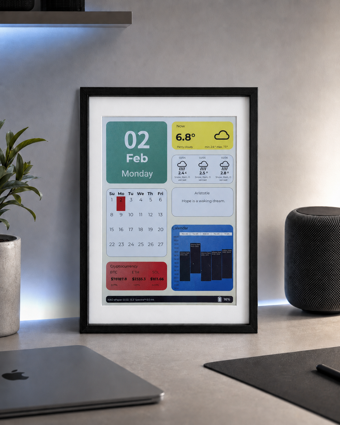
If you want to quickly preview project results or try the basic demo firmware before setting up a development environment, open the reTerminal E-Series Firmware Hub. You can choose a supported reTerminal E Series device and flash demo firmware directly from a browser.
- Arduino Cookbook: ePaper Display — rendering text, graphics, and images on the ePaper screen.
- Arduino Cookbook: Onboard Peripherals — LED, buzzer, buttons, SHT4x sensor, battery monitor, microSD card, and the SD-card image pipeline.
Introduction
This is the second peripherals cookbook for the reTerminal E Series. While the first peripherals cookbook covers the basic I/O peripherals (LED, buzzer, buttons, SHT4x, battery, SD card), this page dives into four more advanced topics:
- Real-Time Clock (RTC) — the onboard PCF8563 RTC chip backed by a CR1220 coin cell, keeping time even when the main battery is removed.
- Low-Power Modes — deep sleep, light sleep, and GPIO wake-up strategies to extend battery life from days to months.
- PDM Microphone — capturing audio through the onboard PDM digital microphone (E1001 / E1002 / E1003 only; E1004 does not have a microphone) and saving WAV files to the microSD card.
- Touch Screen — using the onboard capacitive touch panel on the E1003 (10.3" model) to draw dots on the ePaper display. Only the E1003 has a touch panel.
All example sketches in this cookbook are from the OSHW-reTerminal-Series-E-D repository. The RTC, low-power, and microphone sketches require no additional library installs — everything uses the ESP32 built-in APIs. The touch sketch requires the Seeed_GFX library.
Materials Required
This cookbook applies to the reTerminal E Series. Pick whichever device you have on hand:
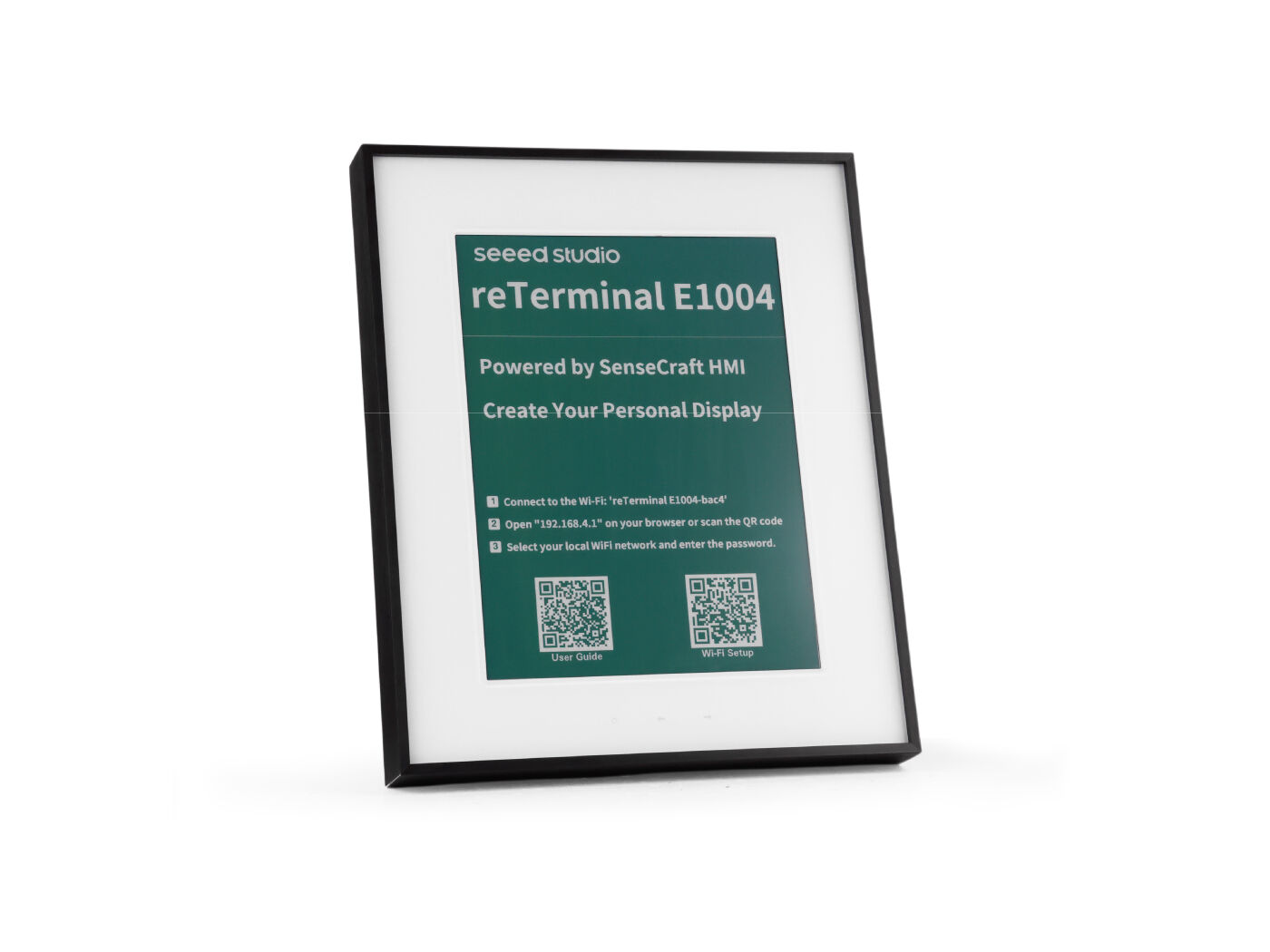
| reTerminal E1001 | reTerminal E1002 | reTerminal E1003 | reTerminal E1004 |
|---|---|---|---|
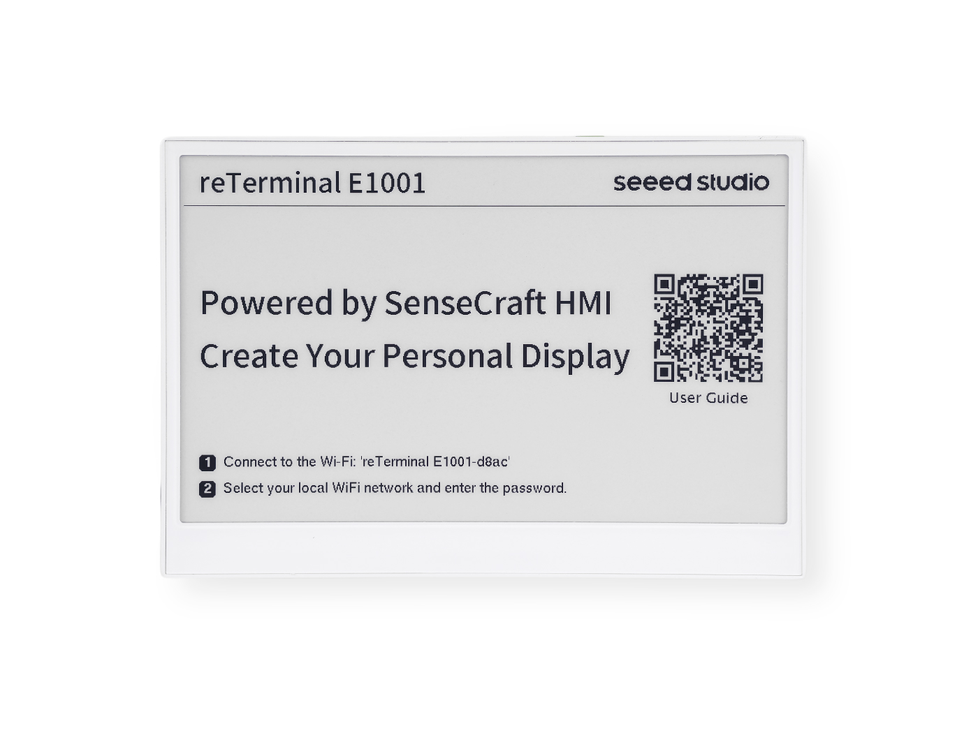 | 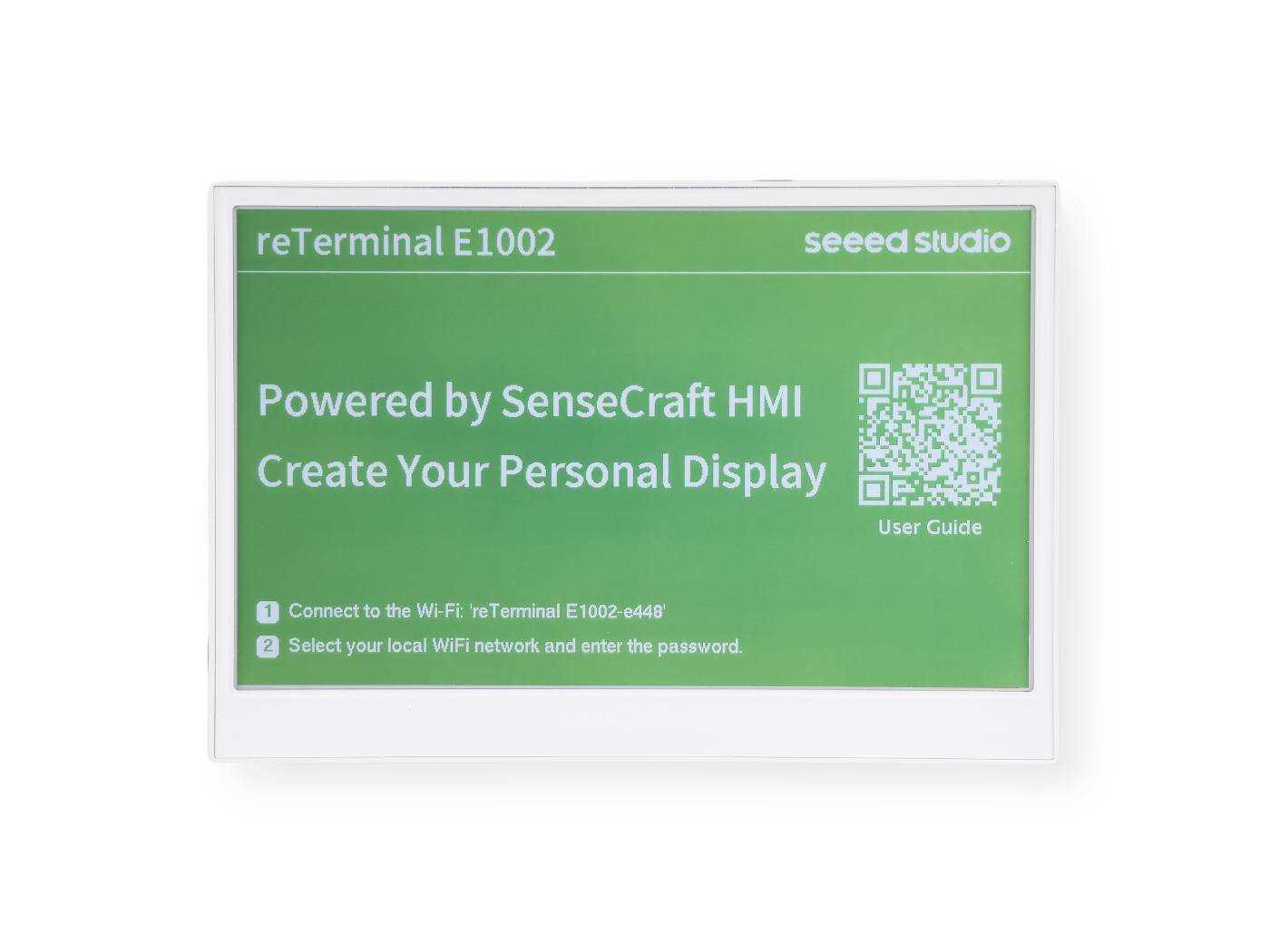 | 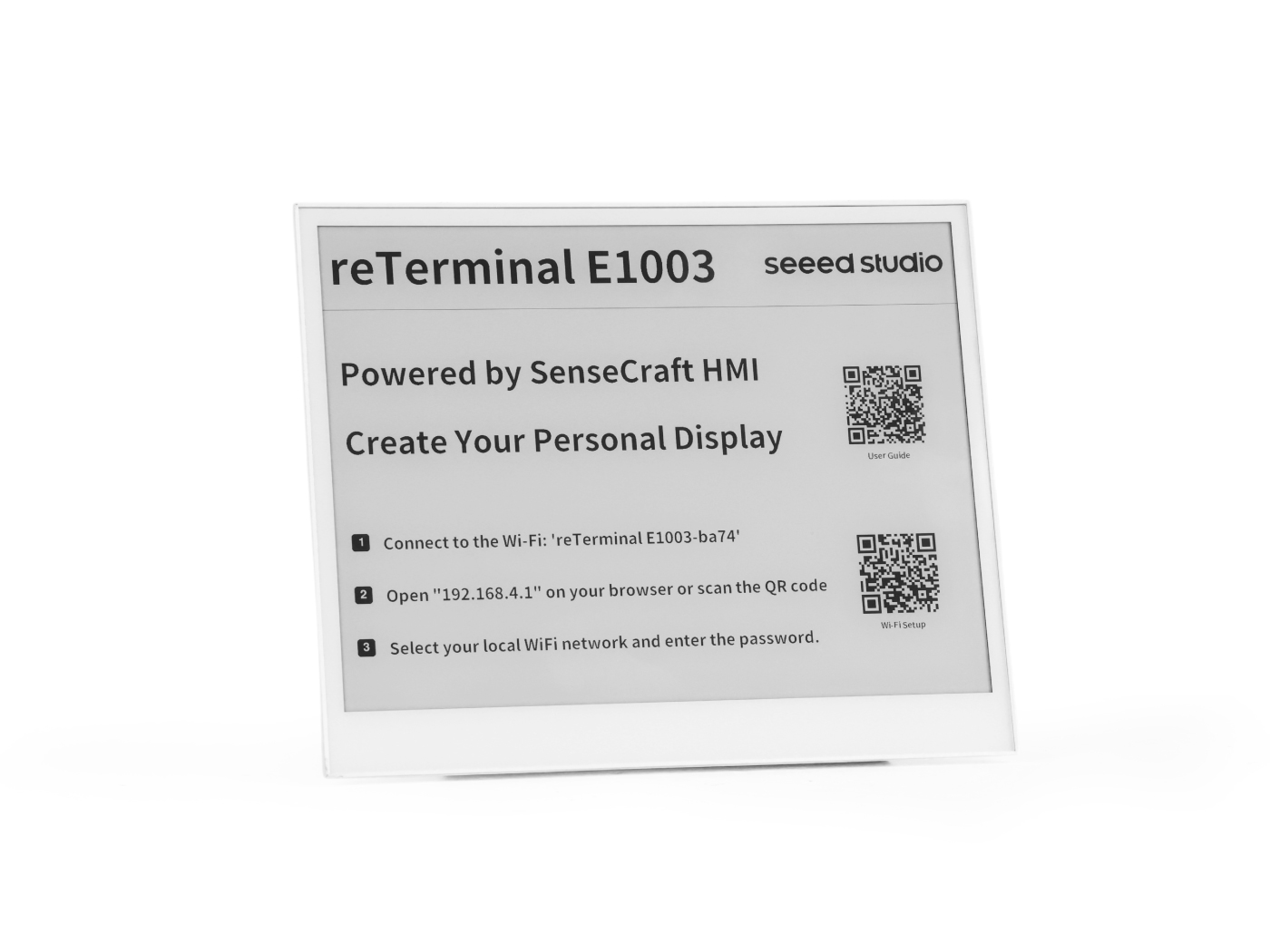 |  |
Prerequisites
Before running any example below, you should already have:
- The Arduino IDE installed with the ESP32 board package (≥ 3.0 for PDM microphone) and the XIAO_ESP32S3 board selected.
- PSRAM set to OPI PSRAM and Flash set to 8 MB in the Tools menu.
- A working USB-C data cable and the correct serial port selected.
- Verified that you can flash a basic sketch to the device — see the environment setup in Arduino Cookbook: ePaper Display if you haven't done this yet.
All sketches in this cookbook print debug information through Serial1 on pins GPIO44 (RX) / GPIO43 (TX) at 115200 baud — this is the carrier USB-UART bridge, not the USB-CDC Serial that the Arduino IDE auto-opens. Open the Arduino Serial Monitor and select the matching port and baud rate to follow along.
Hardware Compatibility Overview
Not every feature in this cookbook is available on all four models. The table below summarises what you can use:
| Feature | E1001 | E1002 | E1003 | E1004 |
|---|---|---|---|---|
| PCF8563 RTC (external, I2C 0x51, CR1220 backup) | ✅ | ✅ | ✅ | ✅ |
| Deep sleep / light sleep | ✅ | ✅ | ✅ | ✅ |
| Button wake-up (KEY0) | ✅ | ✅ | ✅ | ✅ |
| PDM Microphone recording | ✅ | ✅ | ✅ | ❌ |
| Capacitive touch panel | ❌ | ❌ | ✅ | ❌ |
Real-Time Clock (RTC)
Every reTerminal E Series model includes an onboard PCF8563 real-time clock chip from NXP, with its own 32.768 kHz crystal and a CR1220 coin-cell battery holder that keeps time ticking even when the main battery is removed or fully drained.
The CR1220 coin cell is not shipped with the device. You need to purchase a CR1220 battery separately and install it before the RTC can retain time across power cycles.
Installing the CR1220 Battery
The CR1220 battery holder is located on the back of the PCB. The disassembly steps differ slightly between models:
- E1001 / E1002
- E1003
- E1004
Step 1 — Power off the device
Disconnect the USB-C cable and make sure the device is fully powered off.
Step 2 — Remove the back cover
Remove the four screws on the back panel and lift off the rear cover to expose the PCB.
Step 3 — Locate the battery holder
Find the CR1220 coin-cell holder on the PCB (marked BT2 or CR1220).
Step 4 — Insert the battery
Place the CR1220 battery into the holder with the positive (+) side facing up. Gently press until it clicks into place.
Step 5 — Reassemble
Put the back cover back on and tighten the four screws. The RTC is now battery-backed and will keep time even when the main power is disconnected.
Step 1 — Power off the device
Disconnect the USB-C cable and make sure the device is fully powered off.
Step 2 — Remove the back cover
Remove the screws on the back panel and lift off the rear cover to expose the PCB.
Step 3 — Locate the battery holder
Find the CR1220 coin-cell holder on the PCB (marked BT2 or CR1220).
Step 4 — Insert the battery
Place the CR1220 battery into the holder with the positive (+) side facing up. Gently press until it clicks into place.
Step 5 — Reassemble
Put the back cover back on and tighten the screws. The RTC is now battery-backed and will keep time even when the main power is disconnected.
Step 1 — Power off the device
Disconnect the USB-C cable and make sure the device is fully powered off.
Step 2 — Remove the back cover
Remove the screws around the perimeter of the back panel and carefully lift off the rear cover to expose the PCB.
Step 3 — Locate the battery holder
Find the CR1220 coin-cell holder on the PCB (marked BT2 or CR1220).
Step 4 — Insert the battery
Place the CR1220 battery into the holder with the positive (+) side facing up. Gently press until it clicks into place.
Step 5 — Reassemble
Put the back cover back on and tighten all screws. The RTC is now battery-backed and will keep time even when the main power is disconnected.
Hardware Overview
| Parameter | Value |
|---|---|
| Chip | PCF8563M/TR (NXP) |
| Bus | I2C — address 0x51 (fixed in silicon) |
| SCL | GPIO20 |
| SDA | GPIO19 |
| Crystal | 32.768 kHz (OSCI / OSCO pins) |
| Backup battery | CR1220 coin cell — keeps time when main power is removed |
| VL flag | Set by the chip when backup battery voltage is too low; indicates time is unreliable |
Full Sketch: RTC_PCF8563
The complete sketch is available in the repository: examples/RTC_PCF8563/RTC_PCF8563.ino.
Click to expand the full RTC_PCF8563.ino code
// ============================================================
// USER CONFIGURATION
// ============================================================

// --- How to set the initial time ---
//
// OPTION A — Compile-time (recommended):
//   Uncomment USE_COMPILE_TIME.  The C compiler embeds __DATE__ / __TIME__
//   (the exact moment you clicked "Upload") into the binary automatically.
//   No need to type the date by hand — just compile and flash.
//
#define USE_COMPILE_TIME
//
// OPTION B — Manual:
//   Comment out USE_COMPILE_TIME above, then fill in the values below.
//   INITIAL_YEAR must be in the range 2000–2099.
#define INITIAL_YEAR   2026
#define INITIAL_MONTH     5   // 1–12
#define INITIAL_DAY      26   // 1–31
#define INITIAL_HOUR     14   // 0–23
#define INITIAL_MIN       0   // 0–59
#define INITIAL_SEC       0   // 0–59

// --- When to write the time ---
//
// You do NOT need to touch anything here for normal use.
//
// How it works automatically:
//   • New board / battery just replaced → PCF8563 sets VL=1 internally
//     → code detects VL=1 at boot → writes the initial time once → done.
//   • Every reboot after that (battery healthy, VL=0)
//     → stored time is kept, nothing is overwritten.
//
// FORCE_SET_TIME is only for manual re-calibration (e.g. correcting drift).
// If you uncomment it, the clock is overwritten on EVERY boot — make sure
// to comment it out again and re-flash right after calibrating.
//
// #define FORCE_SET_TIME

// ============================================================
// END OF USER CONFIGURATION — no need to edit below this line
// ============================================================

#include <Wire.h>
#include <time.h>
#include <sys/time.h>

// ============================================================
// RtcTime — carries all date/time fields returned by rtcGetTime().
//
// Defined here, right after the #includes, so that Arduino IDE's
// automatic function-prototype injection (which is inserted after
// the last #include) can see the type before using it in prototypes
// like  static bool rtcGetTime(RtcTime &rt).
// ============================================================
struct RtcTime {
    int  year;       // full year (e.g. 2026)
    int  month;      // 1–12
    int  day;        // 1–31
    int  weekday;    // 0=Sunday … 6=Saturday
    int  hour;       // 0–23
    int  minute;     // 0–59
    int  second;     // 0–59
    bool voltageOK;  // false → VL flag set, battery was drained, time unreliable
};

// ---------- Serial debug (carrier USB-UART bridge) ----------
#define PIN_SERIAL_RX   44
#define PIN_SERIAL_TX   43
#define LOG             Serial1

// ---------- I2C pins (identical on all E1001 / E1002 / E1003 / E1004) --------
#define PIN_I2C_SCL     20   // ESP_IO20 / I2C0_SCL
#define PIN_I2C_SDA     19   // ESP_IO19 / I2C0_SDA

// ---------- PCF8563 I2C address (7-bit, fixed in hardware) -------------------
#define PCF8563_ADDR    0x51

// ---------- PCF8563 register map (only the registers used here) --------------
#define REG_CTRL1       0x00   // Control/Status 1 — bit5 STOP halts the clock
#define REG_CTRL2       0x01   // Control/Status 2
#define REG_SECONDS     0x02   // bit7 = VL (voltage-low flag); bits6:0 = seconds
#define REG_MINUTES     0x03   // bits6:0 = minutes
#define REG_HOURS       0x04   // bits5:0 = hours
#define REG_DAYS        0x05   // bits5:0 = day-of-month
#define REG_WEEKDAYS    0x06   // bits2:0 = weekday (0=Sunday)
#define REG_MONTHS      0x07   // bit7 = century (0→2000s, 1→1900s); bits4:0 = month
#define REG_YEARS       0x08   // bits7:0 = year within century (BCD, 00–99)
#define REG_CLKOUT      0x0D   // CLKOUT control — bit7 FE enables clock output pin

// ============================================================
// BCD ↔ decimal conversion
// The PCF8563 stores all time fields in BCD (Binary-Coded Decimal):
//   e.g. decimal 26 → upper nibble=2, lower nibble=6 → 0x26
// ============================================================
static inline uint8_t bcdToDec(uint8_t bcd)
{
    return static_cast<uint8_t>(((bcd >> 4) * 10U) + (bcd & 0x0FU));
}

static inline uint8_t decToBcd(uint8_t dec)
{
    return static_cast<uint8_t>(((dec / 10U) << 4) | (dec % 10U));
}

// ============================================================
// I2C read / write helpers
// ============================================================

// Read `len` consecutive registers starting at `reg` into `buf`.
// Uses a repeated-START (no STOP between write and read) as required by the
// PCF8563 data sheet.
static bool rtcReadRegs(uint8_t reg, uint8_t *buf, size_t len)
{
    Wire.beginTransmission(PCF8563_ADDR);
    Wire.write(reg);
    if (Wire.endTransmission(false) != 0) return false;   // repeated START

    const uint8_t received = Wire.requestFrom(static_cast<uint8_t>(PCF8563_ADDR),
                                              static_cast<uint8_t>(len));
    if (received != len) return false;

    for (size_t i = 0; i < len; i++) {
        buf[i] = static_cast<uint8_t>(Wire.read());
    }
    return true;
}

// Write a single register.
static bool rtcWriteReg(uint8_t reg, uint8_t value)
{
    Wire.beginTransmission(PCF8563_ADDR);
    Wire.write(reg);
    Wire.write(value);
    return Wire.endTransmission() == 0;
}

// ============================================================
// PCF8563 API
// ============================================================

// Check whether the chip responds on the I2C bus.
static bool rtcProbe()
{
    Wire.beginTransmission(PCF8563_ADDR);
    return Wire.endTransmission() == 0;
}

// Clear the STOP bit so the oscillator runs, and disable the CLKOUT pin
// (saves a small amount of power when the clock output is not needed).
static bool rtcInit()
{
    if (!rtcWriteReg(REG_CTRL1, 0x00)) return false;   // STOP=0 → run
    if (!rtcWriteReg(REG_CTRL2, 0x00)) return false;   // clear alarm/timer flags
    if (!rtcWriteReg(REG_CLKOUT, 0x00)) return false;  // FE=0 → disable CLKOUT
    return true;
}

// Return false if the voltage-low flag is set (time data is unreliable).
static bool rtcVoltageOK()
{
    uint8_t sec = 0;
    if (!rtcReadRegs(REG_SECONDS, &sec, 1)) return false;
    return (sec & 0x80U) == 0U;   // VL bit = 0 means voltage has been OK
}

// Write date and time to the RTC.
// `year` must be in the range 2000–2099.
// Weekday is computed automatically from the supplied date.
static bool rtcSetTime(int year, int month, int day,
                       int hour, int minute, int second)
{
    if (year  < 2000 || year  > 2099) return false;
    if (month < 1    || month > 12  ) return false;
    if (day   < 1    || day   > 31  ) return false;
    if (hour  < 0    || hour  > 23  ) return false;
    if (minute < 0   || minute > 59 ) return false;
    if (second < 0   || second > 59 ) return false;

    // Use mktime() to derive the weekday (0=Sunday) from the calendar date.
    struct tm t = {};
    t.tm_year = year - 1900;
    t.tm_mon  = month - 1;
    t.tm_mday = day;
    mktime(&t);   // fills t.tm_wday

    // Write all 7 time registers in one burst starting at REG_SECONDS.
    // The PCF8563 auto-increments the internal address pointer after each byte.
    Wire.beginTransmission(PCF8563_ADDR);
    Wire.write(REG_SECONDS);
    Wire.write(decToBcd(static_cast<uint8_t>(second)));
    Wire.write(decToBcd(static_cast<uint8_t>(minute)));
    Wire.write(decToBcd(static_cast<uint8_t>(hour)));
    Wire.write(decToBcd(static_cast<uint8_t>(day)));
    Wire.write(static_cast<uint8_t>(t.tm_wday));         // weekday is not BCD
    Wire.write(decToBcd(static_cast<uint8_t>(month)));   // century bit = 0 → 2000s
    Wire.write(decToBcd(static_cast<uint8_t>(year % 100)));
    return Wire.endTransmission() == 0;
}

// Read the current date and time from the RTC into an RtcTime struct.
static bool rtcGetTime(RtcTime &rt)
{
    uint8_t raw[7] = {};
    // Burst-read 7 bytes: seconds, minutes, hours, days, weekdays, months, years
    if (!rtcReadRegs(REG_SECONDS, raw, 7)) return false;

    rt.voltageOK = (raw[0] & 0x80U) == 0U;                // VL flag
    rt.second    = bcdToDec(raw[0] & 0x7FU);
    rt.minute    = bcdToDec(raw[1] & 0x7FU);
    rt.hour      = bcdToDec(raw[2] & 0x3FU);
    rt.day       = bcdToDec(raw[3] & 0x3FU);
    rt.weekday   = bcdToDec(raw[4] & 0x07U);
    rt.month     = bcdToDec(raw[5] & 0x1FU);

    const int yr = bcdToDec(raw[6]);
    // Century bit 1 in REG_MONTHS → 1900s, bit 0 → 2000s
    rt.year      = ((raw[5] & 0x80U) != 0U) ? (1900 + yr) : (2000 + yr);

    return true;
}

// ============================================================
// Sync the ESP32's POSIX system clock from the RTC.
// After calling this, standard C functions like time(), localtime(),
// and strftime() will return the correct time.
// ============================================================
static void syncSystemClock(const RtcTime &rt)
{
    struct tm t = {};
    t.tm_year = rt.year - 1900;
    t.tm_mon  = rt.month - 1;
    t.tm_mday = rt.day;
    t.tm_hour = rt.hour;
    t.tm_min  = rt.minute;
    t.tm_sec  = rt.second;
    const time_t epoch = mktime(&t);
    struct timeval tv  = { epoch, 0 };
    settimeofday(&tv, nullptr);
}

// ============================================================
// Compile-time timestamp parser
//
// The C preprocessor provides two string literals in every translation unit:
//   __DATE__  →  "May 26 2026"  (month name, day, 4-digit year)
//   __TIME__  →  "14:53:00"    (HH:MM:SS, 24-hour)
//
// We parse them here so callers get plain integers without any library.
// ============================================================
#ifdef USE_COMPILE_TIME
static void getCompileTime(int &year, int &month, int &day,
                           int &hour, int &minute, int &second)
{
    // Map the 3-letter month abbreviation to 1–12.
    // strncmp compares only the first 3 characters, so this is safe.
    const char *abbr  = __DATE__;       // "May 26 2026"
    const char *names = "JanFebMarAprMayJunJulAugSepOctNovDec";
    month = 1;
    for (int i = 0; i < 12; i++) {
        if (strncmp(abbr, names + i * 3, 3) == 0) { month = i + 1; break; }
    }

    // __DATE__ + 4  →  "26 2026"  (day starts at offset 4)
    // __DATE__ + 7  →  "2026"     (year starts at offset 7)
    day  = atoi(__DATE__ + 4);
    year = atoi(__DATE__ + 7);

    // __TIME__      →  "14:53:00"
    // __TIME__ + 3  →  "53:00"
    // __TIME__ + 6  →  "00"
    hour   = atoi(__TIME__);
    minute = atoi(__TIME__ + 3);
    second = atoi(__TIME__ + 6);
}
#endif  // USE_COMPILE_TIME

// ============================================================
// Helpers
// ============================================================
static const char *kWeekdayNames[] = {
    "Sun", "Mon", "Tue", "Wed", "Thu", "Fri", "Sat"
};

// ============================================================
// Global state
// ============================================================
static unsigned long s_lastPrintMs = 0;

// ============================================================
// setup()
// ============================================================
void setup()
{
    // Use Serial1 (the USB-UART bridge on the carrier board, not USB-CDC).
    // GPIO43 = TX, GPIO44 = RX of the bridge chip.
    LOG.begin(115200, SERIAL_8N1, PIN_SERIAL_RX, PIN_SERIAL_TX);
    delay(500);

    LOG.println("=========================================");
    LOG.println("  RTC_PCF8563 — reTerminal E Series");
    LOG.println("=========================================");

    // ── Step 1: initialise I2C at 400 kHz (PCF8563 supports up to 400 kHz) ──
    Wire.begin(PIN_I2C_SDA, PIN_I2C_SCL);
    Wire.setClock(400000UL);
    LOG.printf("[I2C] Bus started: SDA=GPIO%d  SCL=GPIO%d  400 kHz\n",
               PIN_I2C_SDA, PIN_I2C_SCL);

    // ── Step 2: check the PCF8563 is reachable ──
    LOG.printf("[RTC] Probing PCF8563 at I2C address 0x%02X ...", PCF8563_ADDR);
    if (!rtcProbe()) {
        LOG.println(" NOT FOUND");
        LOG.println("[RTC] FATAL: check wiring and backup battery. Halting.");
        while (true) delay(1000);
    }
    LOG.println(" OK");

    // ── Step 3: clear STOP bit, disable CLKOUT ──
    if (!rtcInit()) {
        LOG.println("[RTC] FATAL: could not initialise PCF8563. Halting.");
        while (true) delay(1000);
    }

    // ── Step 4: decide whether the time needs to be set ──
    //
    // The VL (voltage-low) flag is stored inside the PCF8563 and survives
    // power cycles.  It is set by the chip whenever the backup battery
    // voltage has been too low to keep the clock running reliably.
    // We treat a set VL flag as "time is unknown and must be initialised".
    const bool voltageWasLow = !rtcVoltageOK();

#ifdef FORCE_SET_TIME
    const bool doSetTime = true;
    LOG.println("[RTC] FORCE_SET_TIME defined — overwriting RTC time.");
#else
    const bool doSetTime = voltageWasLow;
    if (voltageWasLow) {
        LOG.println("[RTC] WARNING: VL flag set — backup battery may be depleted.");
        LOG.println("[RTC] Time is unreliable; resetting to INITIAL_* constants.");
    } else {
        LOG.println("[RTC] Battery OK — retaining stored time.");
    }
#endif

    if (doSetTime) {
#ifdef USE_COMPILE_TIME
        // Parse the timestamp baked in at compile time.
        // __DATE__ / __TIME__ are evaluated by the C preprocessor during
        // compilation, so they reflect the moment "Upload" was clicked.
        int cy, cm, cd, ch, cmin, cs;
        getCompileTime(cy, cm, cd, ch, cmin, cs);
        LOG.printf("[RTC] Setting time from compile timestamp: "
                   "%04d-%02d-%02d  %02d:%02d:%02d\n",
                   cy, cm, cd, ch, cmin, cs);
        if (!rtcSetTime(cy, cm, cd, ch, cmin, cs)) {
            LOG.println("[RTC] ERROR: rtcSetTime() failed.");
        }
#else
        LOG.printf("[RTC] Setting time from INITIAL_* constants: "
                   "%04d-%02d-%02d  %02d:%02d:%02d\n",
                   INITIAL_YEAR, INITIAL_MONTH, INITIAL_DAY,
                   INITIAL_HOUR, INITIAL_MIN,   INITIAL_SEC);
        if (!rtcSetTime(INITIAL_YEAR, INITIAL_MONTH, INITIAL_DAY,
                        INITIAL_HOUR, INITIAL_MIN,   INITIAL_SEC)) {
            LOG.println("[RTC] ERROR: rtcSetTime() failed.");
        }
#endif
    }

    // ── Step 5: read back and sync the ESP32 system clock ──
    //
    // The ESP32 has its own software RTC that resets to Jan 1 1970 on each
    // power cycle.  By calling settimeofday() once at boot, we keep the
    // ESP32's POSIX time() / localtime() / strftime() in sync with the
    // hardware RTC so the rest of the firmware can use standard C time APIs.
    RtcTime rt;
    if (rtcGetTime(rt)) {
        syncSystemClock(rt);
        LOG.printf("[RTC] Current time: %04d-%02d-%02d (%s)  %02d:%02d:%02d\n",
                   rt.year, rt.month, rt.day, kWeekdayNames[rt.weekday],
                   rt.hour, rt.minute, rt.second);
        LOG.println("[RTC] ESP32 system clock synced.");
    } else {
        LOG.println("[RTC] ERROR: could not read time after init.");
    }

    LOG.println();
    LOG.println("[READY] Printing time every second.");
}

// ============================================================
// loop()
// ============================================================
void loop()
{
    const unsigned long now = millis();

    // Print time once per second (non-blocking: compare elapsed time instead
    // of calling delay(), so other tasks in loop() are never blocked).
    if (now - s_lastPrintMs >= 1000UL) {
        s_lastPrintMs = now;

        RtcTime rt;
        if (rtcGetTime(rt)) {
            // Show the time read directly from the hardware RTC.
            // The "[VL]" tag warns that the chip saw a low-voltage event.
            LOG.printf("[TIME] %04d-%02d-%02d (%s)  %02d:%02d:%02d%s\n",
                       rt.year, rt.month, rt.day,
                       kWeekdayNames[rt.weekday],
                       rt.hour, rt.minute, rt.second,
                       rt.voltageOK ? "" : "  [VL: battery low!]");

            // ── Optional: also print the time via the ESP32 POSIX API ──
            // This demonstrates that the system clock (synced at boot) is
            // ticking independently of the I2C bus.
            char buf[32];
            time_t epoch = time(nullptr);
            struct tm info;
            localtime_r(&epoch, &info);
            strftime(buf, sizeof(buf), "%Y-%m-%d %H:%M:%S", &info);
            LOG.printf("[SYS ] ESP32 system time: %s\n", buf);

        } else {
            LOG.println("[RTC] ERROR: rtcGetTime() failed — check I2C bus.");
        }
    }
}
How the Code Works
The code follows a 5-step initialization sequence in setup():
- Initialize I2C bus at 400 kHz on GPIO19 (SDA) / GPIO20 (SCL) — the standard reTerminal I2C pins shared with the SHT4x sensor.
- Probe the PCF8563 at address 0x51 to verify the chip is responding.
- Initialize the chip — clear the STOP bit (so the oscillator runs), clear alarm flags, and disable the CLKOUT pin to save power.
- Decide whether to set the time — the PCF8563 has a VL (Voltage Low) flag that is automatically set when the backup battery voltage drops too low. If VL is set (first boot or battery replaced), the code writes the initial time; otherwise it keeps the stored time.
- Sync the ESP32 system clock — after reading the PCF8563 time,
settimeofday()is called so that standard C time functions (time(),localtime(),strftime()) return the correct time throughout the rest of the firmware.
The loop() reads the RTC once per second via I2C and prints the formatted time. The [VL] tag appears if the backup battery voltage is low.
Time-Setting Options
| Option | How to activate | Behaviour |
|---|---|---|
| Compile-time (recommended) | #define USE_COMPILE_TIME | The C preprocessor embeds __DATE__ / __TIME__ (the moment you clicked Upload). Zero-effort — just compile and flash. |
| Manual | Comment out USE_COMPILE_TIME, fill in INITIAL_* constants | You type the exact date and time. Useful for offline environments. |
| Force overwrite | #define FORCE_SET_TIME | Overwrites the RTC on every boot. Use for re-calibration, then comment out and re-flash. |
The VL flag is persistent across power cycles. Once the time is set and the CR1220 battery is healthy, the PCF8563 keeps ticking and subsequent reboots do not overwrite it.
Expected Output
=========================================
  RTC_PCF8563 — reTerminal E Series
=========================================
[RTC] 2026-05-27 (Wed) 14:53:00
[READY] Printing time every second.
[TIME] 2026-05-27 (Wed) 14:53:01
[TIME] 2026-05-27 (Wed) 14:53:02
[TIME] 2026-05-27 (Wed) 14:53:03
If the backup battery is depleted or missing, you will see the [VL: battery low!] warning:
[RTC] WARNING: VL flag set — backup battery may be depleted.
[TIME] 2026-05-27 (Wed) 14:53:01  [VL: battery low!]
Low-Power Modes
The ESP32-S3 supports several power states. The two most useful for battery-powered ePaper applications are deep sleep and light sleep:
| Power State | CPU | Wi-Fi / BT | RAM | RTC | Wake Source |
|---|---|---|---|---|---|
| Active | Running | On | All | On | — |
| Light Sleep | Paused | Off | Retained | On | GPIO, Timer |
| Deep Sleep | Off | Off | Lost (except RTC) | On | GPIO, Timer, Touch |
Full Sketch: LowPower_DeepSleep
The complete sketch is available in the repository: examples/LowPower_DeepSleep/LowPower_DeepSleep.ino.
Click to expand the full LowPower_DeepSleep.ino code
// ============================================================
// USER CONFIGURATION
// ============================================================

// How many seconds to stay awake before entering deep sleep.
#define SLEEP_DELAY_SEC   5

// --- Wake-up button pin ---
// Uncomment the ONE line that matches your device.
// Only GPIO0–GPIO21 can wake the ESP32-S3 from deep sleep.
//
#define PIN_WAKE_BTN   3   // E1001 / E1002 / E1003 — KEY0
// #define PIN_WAKE_BTN   4   // E1004               — KEY0

// ============================================================
// END OF USER CONFIGURATION
// ============================================================

#include "esp_sleep.h"
#include "driver/rtc_io.h"

#define PIN_SERIAL_RX   44
#define PIN_SERIAL_TX   43
#define LOG             Serial1

// Survives deep sleep — increments on every wakeup.
RTC_DATA_ATTR static int s_bootCount = 0;

static const char* wakeupReason()
{
    switch (esp_sleep_get_wakeup_cause()) {
        case ESP_SLEEP_WAKEUP_EXT1:  return "GPIO button (EXT1)";
        default:                     return "power-on / manual reset";
    }
}

void setup()
{
    s_bootCount++;

    LOG.begin(115200, SERIAL_8N1, PIN_SERIAL_RX, PIN_SERIAL_TX);
    delay(100);

    LOG.println("========================================");
    LOG.println("  LowPower_DeepSleep — reTerminal E");
    LOG.println("========================================");
    LOG.printf("[WAKE] Boot #%d — wakeup: %s\n", s_bootCount, wakeupReason());
    LOG.printf("[WAKE] Entering deep sleep in %d seconds...\n", SLEEP_DELAY_SEC);
    LOG.printf("[WAKE] Press GPIO%d button to wake up.\n", PIN_WAKE_BTN);

    delay((uint32_t)SLEEP_DELAY_SEC * 1000);

    esp_sleep_enable_ext1_wakeup(1ULL << PIN_WAKE_BTN, ESP_EXT1_WAKEUP_ANY_LOW);

    // Normal GPIO pull-up is off during deep sleep; use keep-alive domain instead.
    rtc_gpio_pullup_en(static_cast<gpio_num_t>(PIN_WAKE_BTN));
    rtc_gpio_pulldown_dis(static_cast<gpio_num_t>(PIN_WAKE_BTN));

    LOG.println("[SLEEP] Entering deep sleep now.");
    LOG.flush();
    delay(10);

    esp_deep_sleep_start();
}

void loop()
{
    // esp_deep_sleep_start() in setup() never returns, so loop() is never reached.
    // If you see this message, deep sleep failed to start.
    LOG.println("[ERROR] deep sleep did not start!");
    delay(1000);
}
How the Code Works
setup()starts — increments theRTC_DATA_ATTRboot counter (this variable is kept in the ESP32-S3's RTC memory domain, so it survives deep sleep).- Prints status — shows the boot count and why the chip woke up (GPIO button vs power-on reset).
- Waits
SLEEP_DELAY_SECseconds (default 5) — this gives you time to read the serial output. - Configures wake-up source —
esp_sleep_enable_ext1_wakeup()registers the button pin (KEY0). The wake-up level isLOWbecause the buttons are active-low with hardware pull-ups. - Enables RTC pull-up — normal GPIO pull-ups are disabled during deep sleep.
rtc_gpio_pullup_en()uses the RTC-domain pull-up to keep the button line HIGH while asleep. - Enters deep sleep —
esp_deep_sleep_start()powers down everything except the RTC domain. Current drops to ~14 µA. - On button press — the RTC domain detects the GPIO falling edge, the chip reboots, and
setup()runs again from step 1.
loop() contains a print statement that should never execute. If you see [ERROR] deep sleep did not start! in the serial monitor, deep sleep failed. Silence after [SLEEP] means the device is truly asleep.
Button Wake-Up Pin Selection
The wake-up button differs between models due to the GPIO layout:
| Model | Wake-up pin | PIN_WAKE_BTN | Notes |
|---|---|---|---|
| E1001 / E1002 / E1003 | GPIO3 (KEY0) | 3 | Right-side button (Green Button on E1001/E1002) |
| E1004 | GPIO4 (KEY0) | 4 | Right direction button (front panel) |
Uncomment the correct line in the USER CONFIGURATION section before flashing.
Expected Output
First boot (power-on):
========================================
  LowPower_DeepSleep — reTerminal E
========================================
[WAKE] Boot #1 — wakeup: power-on / manual reset
[WAKE] Entering deep sleep in 5 seconds...
[WAKE] Press GPIO3 button to wake up.
[SLEEP] Entering deep sleep now.
After pressing KEY0 to wake up:
========================================
  LowPower_DeepSleep — reTerminal E
========================================
[WAKE] Boot #2 — wakeup: GPIO button (EXT1)
[WAKE] Entering deep sleep in 5 seconds...
[WAKE] Press GPIO3 button to wake up.
[SLEEP] Entering deep sleep now.
Wake → Work → Sleep Pattern
A common pattern for ePaper applications is:
- Wake up from deep sleep (timer or button).
- Read the RTC for timestamping.
- Read sensors (SHT4x, battery, etc.).
- Connect to Wi-Fi and fetch data — if needed.
- Update the ePaper display with the new information.
- Go back to deep sleep until the next scheduled wake-up.
To add a timer wake-up in addition to the button wake-up, simply add:
esp_sleep_enable_timer_wakeup(30 * 60 * 1000000ULL); // 30 minutes
before calling esp_deep_sleep_start(). Both wake sources can be active simultaneously — the first one to trigger wins.
Microphone (E1001 / E1002 / E1003)
The reTerminal E1004 does not include an onboard microphone. The examples in this section apply only to E1001, E1002, and E1003. If you are using an E1004, skip this section.
The reTerminal E1001 / E1002 / E1003 include an onboard PDM (Pulse Density Modulation) digital microphone. PDM microphones output a 1-bit sigma-delta stream that is decoded by the ESP32-S3's built-in PDM peripheral — no external codec chip is needed.
Hardware Overview
| Signal | GPIO Pin | Description |
|---|---|---|
| PDM_CLK | GPIO42 | Clock output to microphone |
| PDM_DATA | GPIO41 | 1-bit data input from microphone |
| MIC_PWR_EN | GPIO38 | Microphone power enable (active HIGH) — must be driven HIGH before use |
The pins are the same across E1001, E1002, and E1003. The microphone power enable pin (GPIO38) controls a load switch (TPS22916CYFPR) — you must drive it HIGH before recording and can drive it LOW afterward to save power.
The sketch uses the ESP-IDF 5.x PDM-RX API (driver/i2s_pdm.h) which is only available in Arduino ESP32 core version 3.0 and above. Make sure your board package is up to date.
Full Sketch: MicRecordToSD
The complete sketch is available in the repository: examples/MicRecordToSD/MicRecordToSD.ino.
Click to expand the full MicRecordToSD.ino code
// ============================================================
// USER CONFIGURATION
// ============================================================

// Uncomment ONE line to select your hardware model:
// #define DEVICE_E1001_E1002   // reTerminal E1001 or E1002
#define DEVICE_E1003      // reTerminal E1003

// Recording parameters
#define SAMPLE_RATE      16000U  // Sample rate in Hz (8000 / 16000 / 44100)
#define MAX_RECORD_SECS  30      // Auto-stop after this many seconds (0 = unlimited)
#define RECORD_DIR       "/REC"  // Directory on the SD card root

// ============================================================
// END OF USER CONFIGURATION — no need to edit below this line
// ============================================================

#include <SD.h>
#include <SPI.h>
#include <driver/i2s_pdm.h>    // ESP-IDF 5.x PDM-RX API (Arduino ESP32 >= 3.0)
#include <driver/i2s_common.h>

// ---------- Serial debug ---------
#define PIN_SERIAL_RX   44
#define PIN_SERIAL_TX   43
#define LOG             Serial1

// ---------- PDM Microphone -------
// Same on E1001, E1002, and E1003.
#define PIN_MIC_CLK     42   // GPIO42 — PDM_CLK  (R109 in schematic)
#define PIN_MIC_DATA    41   // GPIO41 — PDM_DATA (R110 in schematic)
#define PIN_MIC_PWR_EN  38   // GPIO38 — MIC power enable (TPS22916CYFPR EN, ESP_IO3B)

// ---------- SD Card --------------
// SPI bus is shared with the ePaper display; a separate CS keeps them independent.
#define PIN_SD_DET       15  // Card detect (LOW = card present)
#define PIN_SD_CS        14  // SPI Chip Select
#define PIN_SD_MISO       8
#define PIN_SD_MOSI       9
#define PIN_SD_SCK        7

// ---------- User Button ----------
#define PIN_BTN_KEY0      3  // KEY0 — active LOW (hardware pull-up)

// ---------- Model-specific pins --
#if defined(DEVICE_E1001_E1002)
  #define PIN_SD_EN    16    // GPIO16 — SD card power enable
  #define PIN_LED       6    // GPIO6  — onboard LED (inverted: LOW = ON)
#elif defined(DEVICE_E1003)
  #define PIN_SD_EN    39    // GPIO39 — SD card power enable
  #define PIN_LED      16    // GPIO16 — onboard LED (inverted: LOW = ON)
#else
  #error "Please define DEVICE_E1001_E1002 or DEVICE_E1003 in the USER CONFIGURATION section."
#endif

// ---------- I2S / Audio ----------
#define I2S_PORT          I2S_NUM_0
#define DMA_BUF_COUNT     8     // number of DMA descriptors
#define DMA_BUF_LEN       512   // frames per DMA descriptor
#define BITS_PER_SAMPLE   16
#define AUDIO_CHANNELS    1
#define BYTES_PER_SAMPLE  (BITS_PER_SAMPLE / 8)
#define BYTES_PER_SEC     (SAMPLE_RATE * AUDIO_CHANNELS * BYTES_PER_SAMPLE)

// Single-read chunk: matches one DMA buffer (512 frames × 2 bytes = 1024 bytes)
#define READ_BUF_BYTES    (DMA_BUF_LEN * BYTES_PER_SAMPLE)
static uint8_t s_dmaBuf[READ_BUF_BYTES];

// ============================================================
// WAV file header (44 bytes, little-endian)
// ============================================================
#pragma pack(push, 1)
struct WavHeader {
    // RIFF chunk
    char     riffTag[4];      // "RIFF"
    uint32_t riffSize;        // file size − 8
    char     waveTag[4];      // "WAVE"
    // fmt sub-chunk
    char     fmtTag[4];       // "fmt "
    uint32_t fmtSize;         // 16 for PCM
    uint16_t audioFormat;     // 1 = PCM
    uint16_t numChannels;     // 1 = mono
    uint32_t sampleRate;
    uint32_t byteRate;        // sampleRate × channels × bytesPerSample
    uint16_t blockAlign;      // channels × bytesPerSample
    uint16_t bitsPerSample;
    // data sub-chunk
    char     dataTag[4];      // "data"
    uint32_t dataSize;        // audio payload in bytes
};
#pragma pack(pop)

static_assert(sizeof(WavHeader) == 44, "WavHeader must be 44 bytes");

// ============================================================
// Global state
// ============================================================
static i2s_chan_handle_t s_rxHandle    = nullptr;  // ESP-IDF 5.x channel handle
static SPIClass          s_spiSD(HSPI);
static File        s_wavFile;
static bool        s_recording     = false;
static uint32_t    s_recordedBytes = 0;
static uint32_t    s_fileIndex     = 1;

// Button debounce
static bool          s_lastRawBtn    = HIGH;
static bool          s_stableBtn     = HIGH;
static unsigned long s_debounceMs    = 0;
static const unsigned long DEBOUNCE_DELAY = 50;

// LED blink
static unsigned long s_lastBlinkMs  = 0;
static bool          s_ledState     = false;

// ============================================================
// LED helpers (inverted logic)
// ============================================================
static void ledOn()  { digitalWrite(PIN_LED, LOW);  }
static void ledOff() { digitalWrite(PIN_LED, HIGH); }

// ============================================================
// WAV helpers
// ============================================================
static void writeWavHeader(File& f, uint32_t dataBytes)
{
    WavHeader h;
    memcpy(h.riffTag,  "RIFF", 4);
    h.riffSize     = 36 + dataBytes;
    memcpy(h.waveTag,  "WAVE", 4);
    memcpy(h.fmtTag,   "fmt ", 4);
    h.fmtSize      = 16;
    h.audioFormat  = 1;
    h.numChannels  = AUDIO_CHANNELS;
    h.sampleRate   = SAMPLE_RATE;
    h.byteRate     = BYTES_PER_SEC;
    h.blockAlign   = AUDIO_CHANNELS * BYTES_PER_SAMPLE;
    h.bitsPerSample = BITS_PER_SAMPLE;
    memcpy(h.dataTag,  "data", 4);
    h.dataSize     = dataBytes;
    f.write(reinterpret_cast<const uint8_t*>(&h), sizeof(h));
}

// ============================================================
// SD card helpers
// ============================================================
static bool mountSD()
{
    pinMode(PIN_SD_EN, OUTPUT);
    digitalWrite(PIN_SD_EN, HIGH);
    delay(10);

    s_spiSD.end();
    s_spiSD.begin(PIN_SD_SCK, PIN_SD_MISO, PIN_SD_MOSI, PIN_SD_CS);

    if (!SD.begin(PIN_SD_CS, s_spiSD)) {
        LOG.println("[SD] Initialization failed — check card and formatting (FAT32).");
        return false;
    }
    LOG.printf("[SD] Mounted. Type: %s  Size: %llu MB\n",
               SD.cardType() == CARD_SDHC ? "SDHC" : "SD",
               SD.cardSize() / (1024ULL * 1024ULL));
    return true;
}

static String nextFilename()
{
    if (!SD.exists(RECORD_DIR)) {
        SD.mkdir(RECORD_DIR);
    }
    char buf[32];
    while (true) {
        snprintf(buf, sizeof(buf), "%s/REC_%04u.WAV", RECORD_DIR, s_fileIndex);
        if (!SD.exists(buf)) break;
        s_fileIndex++;
        if (s_fileIndex > 9999) s_fileIndex = 1;
    }
    return String(buf);
}

// ============================================================
// PDM / I2S helpers  (ESP-IDF 5.x new-API, Arduino ESP32 >= 3.0)
// ============================================================
static bool initMic()
{
    // ── Step 1: power up the microphone via the load switch ──
    LOG.println("[MIC] Powering on microphone...");
    pinMode(PIN_MIC_PWR_EN, OUTPUT);
    digitalWrite(PIN_MIC_PWR_EN, HIGH);
    delay(50);  // give the LDO and PDM decimation filter time to start up

    // ── Step 2: create an I2S RX channel ──
    LOG.println("[MIC] Creating I2S channel...");
    i2s_chan_config_t chanCfg = I2S_CHANNEL_DEFAULT_CONFIG(I2S_NUM_0, I2S_ROLE_MASTER);
    chanCfg.dma_desc_num  = DMA_BUF_COUNT;
    chanCfg.dma_frame_num = DMA_BUF_LEN;
    chanCfg.auto_clear    = true;

    esp_err_t err = i2s_new_channel(&chanCfg, nullptr, &s_rxHandle);
    if (err != ESP_OK) {
        LOG.printf("[MIC] i2s_new_channel failed: 0x%x\n", err);
        return false;
    }

    // ── Step 3: configure PDM-RX mode ──
    LOG.println("[MIC] Configuring PDM-RX mode...");
    i2s_pdm_rx_config_t pdmCfg = {};
    pdmCfg.clk_cfg  = I2S_PDM_RX_CLK_DEFAULT_CONFIG(SAMPLE_RATE);
    pdmCfg.slot_cfg = I2S_PDM_RX_SLOT_DEFAULT_CONFIG(I2S_DATA_BIT_WIDTH_16BIT,
                                                      I2S_SLOT_MODE_MONO);
    pdmCfg.gpio_cfg.clk             = static_cast<gpio_num_t>(PIN_MIC_CLK);
    pdmCfg.gpio_cfg.din             = static_cast<gpio_num_t>(PIN_MIC_DATA);
    pdmCfg.gpio_cfg.invert_flags.clk_inv = false;

    err = i2s_channel_init_pdm_rx_mode(s_rxHandle, &pdmCfg);
    if (err != ESP_OK) {
        LOG.printf("[MIC] i2s_channel_init_pdm_rx_mode failed: 0x%x\n", err);
        i2s_del_channel(s_rxHandle);
        s_rxHandle = nullptr;
        return false;
    }

    // ── Step 4: enable (starts the clock and DMA) ──
    LOG.println("[MIC] Enabling channel...");
    err = i2s_channel_enable(s_rxHandle);
    if (err != ESP_OK) {
        LOG.printf("[MIC] i2s_channel_enable failed: 0x%x\n", err);
        i2s_del_channel(s_rxHandle);
        s_rxHandle = nullptr;
        return false;
    }

    // ── Step 5: warm-up — discard a few DMA buffers with a finite timeout ──
    // The PDM decimation filter needs several milliseconds to settle.
    // Using a 500 ms timeout instead of portMAX_DELAY prevents hanging if
    // the hardware is not producing data for any reason.
    LOG.println("[MIC] Warming up PDM filter...");
    size_t dummy;
    for (int i = 0; i < 3; i++) {
        i2s_channel_read(s_rxHandle, s_dmaBuf, sizeof(s_dmaBuf),
                         &dummy, pdMS_TO_TICKS(500));
    }

    LOG.printf("[MIC] PDM initialized. Rate=%u Hz  Bits=%d  CLK=GPIO%d  DATA=GPIO%d\n",
               SAMPLE_RATE, BITS_PER_SAMPLE, PIN_MIC_CLK, PIN_MIC_DATA);
    return true;
}

// ============================================================
// Recording control
// ============================================================
static bool startRecording()
{
    String fname = nextFilename();
    s_wavFile = SD.open(fname, FILE_WRITE);
    if (!s_wavFile) {
        LOG.printf("[REC] Cannot create file: %s\n", fname.c_str());
        return false;
    }
    writeWavHeader(s_wavFile, 0);   // placeholder — filled in when recording stops
    s_recordedBytes = 0;
    s_recording     = true;
    ledOn();
    LOG.printf("[REC] Recording started → %s\n", fname.c_str());
    return true;
}

static void stopRecording()
{
    s_recording = false;
    ledOff();

    // Seek back to the beginning and rewrite the header with the real data size.
    s_wavFile.seek(0);
    writeWavHeader(s_wavFile, s_recordedBytes);
    s_wavFile.close();

    float seconds = static_cast<float>(s_recordedBytes) / BYTES_PER_SEC;
    LOG.printf("[REC] Recording stopped. %u bytes saved (%.1f s).\n",
               s_recordedBytes, seconds);
    s_fileIndex++;
}

// ============================================================
// setup()
// ============================================================
void setup()
{
    LOG.begin(115200, SERIAL_8N1, PIN_SERIAL_RX, PIN_SERIAL_TX);
    delay(500);   // brief pause for the serial bridge to enumerate

    LOG.println("=========================================");
    LOG.println("  MicRecordToSD — reTerminal E Series");
#if defined(DEVICE_E1001_E1002)
    LOG.println("  Device: E1001 / E1002");
#else
    LOG.println("  Device: E1003");
#endif
    LOG.println("=========================================");

    // LED
    pinMode(PIN_LED, OUTPUT);
    ledOff();

    // Startup blink to confirm power-on
    for (int i = 0; i < 3; i++) {
        ledOn();  delay(100);
        ledOff(); delay(100);
    }

    // User button (hardware pull-up, active LOW)
    pinMode(PIN_BTN_KEY0, INPUT);

    // SD card
    LOG.println("[SD] Mounting...");
    if (!mountSD()) {
        LOG.println("[SD] FATAL: could not mount SD card. Halting.");
        while (true) { delay(1000); }
    }

    // PDM microphone
    LOG.println("[MIC] Initializing PDM microphone...");
    if (!initMic()) {
        LOG.println("[MIC] FATAL: microphone init failed. Halting.");
        while (true) { delay(1000); }
    }

    LOG.println();
    LOG.printf("[READY] Press KEY0 to start recording (max %d s).\n", MAX_RECORD_SECS);
    LOG.printf("[READY] Files will be saved to %s/REC_XXXX.WAV\n", RECORD_DIR);
}

// ============================================================
// loop()
// ============================================================
void loop()
{
    // -------------------------------------------------------
    // Debounced button handling
    // -------------------------------------------------------
    const bool rawBtn = digitalRead(PIN_BTN_KEY0);
    if (rawBtn != s_lastRawBtn) {
        s_debounceMs = millis();
        s_lastRawBtn = rawBtn;
    }
    if ((millis() - s_debounceMs) > DEBOUNCE_DELAY && rawBtn != s_stableBtn) {
        s_stableBtn = rawBtn;
        if (s_stableBtn == LOW) {   // falling edge = button pressed
            if (!s_recording) {
                startRecording();
            } else {
                stopRecording();
            }
        }
    }

    // -------------------------------------------------------
    // Audio capture (only while recording)
    // -------------------------------------------------------
    if (s_recording) {
        size_t bytesRead = 0;
        // Use a 200 ms timeout so the button check in the next loop iteration
        // is still reached even if the DMA is unexpectedly slow.
        const esp_err_t err = i2s_channel_read(s_rxHandle, s_dmaBuf, sizeof(s_dmaBuf),
                                               &bytesRead, pdMS_TO_TICKS(200));
        if (err == ESP_OK && bytesRead > 0) {
            s_wavFile.write(s_dmaBuf, bytesRead);
            s_recordedBytes += bytesRead;
        } else if (err != ESP_OK && err != ESP_ERR_TIMEOUT) {
            LOG.printf("[REC] i2s_channel_read error: 0x%x — stopping.\n", err);
            stopRecording();
            return;
        }

        // Auto-stop when MAX_RECORD_SECS is reached
        if (MAX_RECORD_SECS > 0 && s_recordedBytes >= static_cast<uint32_t>(BYTES_PER_SEC) * MAX_RECORD_SECS) {
            LOG.println("[REC] Maximum duration reached — stopping automatically.");
            stopRecording();
            return;
        }

        // LED blink at 500 ms period while recording
        const unsigned long now = millis();
        if (now - s_lastBlinkMs >= 500) {
            s_lastBlinkMs = now;
            s_ledState    = !s_ledState;
            if (s_ledState) ledOn(); else ledOff();
        }
    }
}
How the Code Works
Initialization sequence (setup()):
- Startup blink — the onboard LED blinks 3 times to confirm power-on.
- Mount the SD card — powers on the SD slot via
PIN_SD_EN, initializes the HSPI bus, and callsSD.begin(). - Initialize the PDM microphone — this is a 4-step process:
- Power on the microphone via
PIN_MIC_PWR_EN(GPIO38) — drives the TPS22916 load switch HIGH. - Create an I2S channel using
i2s_new_channel(). - Configure PDM-RX mode with
i2s_channel_init_pdm_rx_mode()— sets the sample rate, bit depth (16-bit), mono mode, and GPIO pins. - Enable and warm up —
i2s_channel_enable()starts the clock, then 3 DMA buffers are read and discarded to let the sigma-delta decimation filter settle.
- Power on the microphone via
Recording loop (loop()):
- Button debounce — reads KEY0 with a 50 ms debounce window. On falling edge (pressed):
- If not recording → start recording (create WAV file, write placeholder header).
- If recording → stop recording (rewrite header with actual size, close file).
- Audio capture —
i2s_channel_read()reads one DMA buffer (512 samples = 1024 bytes) at a time with a 200 ms timeout. Data is written directly to the SD card. - Auto-stop — if
MAX_RECORD_SECSis reached, recording stops automatically. - LED blink — the LED blinks at 500 ms intervals while recording is active.
Model-Specific Configuration
The sketch requires you to uncomment one #define in the USER CONFIGURATION section:
| Model | #define | SD_EN pin | LED pin |
|---|---|---|---|
| E1001 / E1002 | DEVICE_E1001_E1002 | GPIO16 | GPIO6 |
| E1003 | DEVICE_E1003 | GPIO39 | GPIO16 |
Preparing the SD Card
For instructions on inserting and formatting the microSD card, see the Using the MicroSD Card section in the first peripherals cookbook.
The reTerminal E Series supports microSD cards up to 64 GB, formatted as FAT32.
The reTerminal E1004 comes with a microSD card already inserted. You do not need to purchase or install one separately. For other models (E1001 / E1002 / E1003), you need to insert a card yourself.
Quick preparation:
- Format the microSD card as FAT32 (skip this step for E1004 if using the pre-installed card).
- The sketch will automatically create a
/RECdirectory on first recording. - Make sure the card is inserted before powering on.
Expected Output
=========================================
  MicRecordToSD — reTerminal E Series
=========================================
[SD] Mounting...
[SD] Mounted. Size: 31918 MB
[MIC] Powering on microphone...
[MIC] Creating I2S channel...
[MIC] Configuring PDM-RX mode...
[MIC] Enabling channel...
[MIC] Warming up PDM filter...
[MIC] PDM ready. Rate=16000  CLK=GPIO42  DATA=GPIO41
[READY] Press KEY0 to record (max 30 s).
[READY] Files saved to /REC/REC_XXXX.WAV

[REC] Started → /REC/REC_0001.WAV
[REC] Stopped. 320000 bytes (10.0 s).
Touch Screen (E1003 Only)
The capacitive touch panel is only available on the reTerminal E1003 (10.3" model). The E1001, E1002, and E1004 do not have a touch panel. If you are using any model other than E1003, skip this section.
The reTerminal E1003 features a GT911 capacitive touch controller connected via I2C. Combined with the 16-level gray ePaper display, you can build interactive applications that respond to screen taps.
Hardware Overview
| Parameter | Value |
|---|---|
| Touch controller | GT911 (Goodix) |
| Bus | I2C0 — address 0x5D or 0x14 (auto-detected) |
| SDA | GPIO19 |
| SCL | GPIO20 |
| INT | GPIO2 |
| RESET | GPIO48 |
| Panel resolution | 1872 × 1404 px |
The touch controller shares the same I2C bus (GPIO19/GPIO20) with the PCF8563 RTC and the SHT4x sensor.
Full Sketch: E1003_TouchDraw
The complete sketch is available in the repository: examples/E1003_TouchDraw/E1003_TouchDraw.ino.
Click to expand the full E1003_TouchDraw.ino code
#include <Arduino.h>
#include <Wire.h>

#include "driver.h"
#include "TFT_eSPI.h"
#include "TouchMapper.h"

// ---------- Serial status logs (carrier USB-UART bridge) ----------
#define PIN_SERIAL_RX       44
#define PIN_SERIAL_TX       43
#define LOG                 Serial1

// ---------- E1003 touch pins from the schematic ----------
#define PIN_I2C_SDA         19
#define PIN_I2C_SCL         20
#define PIN_TOUCH_INT        2
#define PIN_TOUCH_RESET     48

// ---------- GT911 register map ----------
#define GT911_ADDR_1      0x5D
#define GT911_ADDR_2      0x14
#define GT911_REG_COMMAND 0x8040
#define GT911_REG_PRODUCT 0x8140
#define GT911_REG_STATUS  0x814E
#define GT911_REG_POINT1  0x814F
#define GT911_REG_MAX_X   0x8048

#define TOUCH_POLL_MS       30
#define DRAW_MIN_MS        450
#define DRAW_MIN_DELTA_PX   12
#define DOT_RADIUS          10

#define E1003_PANEL_WIDTH   1872
#define E1003_PANEL_HEIGHT  1404

// Set to 1 only when the panel has obvious ghosting and you want a slow
// black-white cleanup before the example screen appears. Normal boot uses one
// refresh in drawStartupScreen().
#define STRONG_BOOT_CLEAR    0

static EPaper display_;

static uint8_t s_touchAddr = 0;
static uint16_t s_touchMaxX = 1;
static uint16_t s_touchMaxY = 1;
static uint16_t s_lastRawX = 0;
static uint16_t s_lastRawY = 0;
static bool s_haveLastPoint = false;
static TouchDisplayPoint s_lastPoint = {0, 0};
static TouchDisplayPoint s_displaySize = {E1003_PANEL_WIDTH, E1003_PANEL_HEIGHT};
static bool s_displayReady = false;
static unsigned long s_lastPollMs = 0;
static unsigned long s_lastDrawMs = 0;

static void updateDisplaySize()
{
  resolveDisplaySize(static_cast<uint16_t>(display_.width()),
                     static_cast<uint16_t>(display_.height()),
                     E1003_PANEL_WIDTH,
                     E1003_PANEL_HEIGHT,
                     &s_displaySize);
}

static bool i2cRead16(uint8_t addr, uint16_t reg, uint8_t* buf, size_t len)
{
  Wire.beginTransmission(addr);
  Wire.write(static_cast<uint8_t>(reg >> 8));
  Wire.write(static_cast<uint8_t>(reg & 0xFF));
  if (Wire.endTransmission(false) != 0) return false;

  const uint8_t got = Wire.requestFrom(addr, static_cast<uint8_t>(len));
  if (got != len) return false;

  for (size_t i = 0; i < len; i++) {
    buf[i] = static_cast<uint8_t>(Wire.read());
  }
  return true;
}

static bool i2cWrite16(uint8_t addr, uint16_t reg, uint8_t value)
{
  Wire.beginTransmission(addr);
  Wire.write(static_cast<uint8_t>(reg >> 8));
  Wire.write(static_cast<uint8_t>(reg & 0xFF));
  Wire.write(value);
  return Wire.endTransmission() == 0;
}

static void resetTouchController()
{
  pinMode(PIN_TOUCH_INT, INPUT);
  pinMode(PIN_TOUCH_RESET, OUTPUT);

  digitalWrite(PIN_TOUCH_RESET, LOW);
  delay(20);
  digitalWrite(PIN_TOUCH_RESET, HIGH);
  delay(120);
}

static bool probeGt911(uint8_t addr)
{
  uint8_t product[4] = {};
  if (!i2cRead16(addr, GT911_REG_PRODUCT, product, sizeof(product))) {
    return false;
  }
  LOG.printf("[touch] GT9xx found at 0x%02X, product: %c%c%c%c\n",
             addr, product[0], product[1], product[2], product[3]);
  return true;
}

static void readTouchLimits()
{
  uint8_t raw[4] = {};
  if (!i2cRead16(s_touchAddr, GT911_REG_MAX_X, raw, sizeof(raw))) {
    s_touchMaxX = s_displaySize.x;
    s_touchMaxY = s_displaySize.y;
    return;
  }

  const uint16_t maxX = static_cast<uint16_t>(raw[0] | (raw[1] << 8));
  const uint16_t maxY = static_cast<uint16_t>(raw[2] | (raw[3] << 8));

  if (maxX > 0 && maxY > 0) {
    s_touchMaxX = maxX;
    s_touchMaxY = maxY;
  }

  LOG.printf("[touch] Touch range: %u x %u, display: %u x %u\n",
             s_touchMaxX, s_touchMaxY, s_displaySize.x, s_displaySize.y);
}

static bool initTouch()
{
  resetTouchController();

  if (probeGt911(GT911_ADDR_1)) {
    s_touchAddr = GT911_ADDR_1;
  } else if (probeGt911(GT911_ADDR_2)) {
    s_touchAddr = GT911_ADDR_2;
  } else {
    LOG.println("[touch] GT9xx touch controller not found.");
    return false;
  }

  readTouchLimits();
  i2cWrite16(s_touchAddr, GT911_REG_COMMAND, 0x00);
  i2cWrite16(s_touchAddr, GT911_REG_STATUS, 0x00);
  pinMode(PIN_TOUCH_INT, INPUT_PULLUP);
  LOG.println("[touch] Ready.");
  return true;
}

static bool readTouchPoint(TouchDisplayPoint* point)
{
  uint8_t status = 0;
  if (!i2cRead16(s_touchAddr, GT911_REG_STATUS, &status, 1)) {
    LOG.println("[touch] Failed to read GT911 status register.");
    return false;
  }

  const int intLevel = digitalRead(PIN_TOUCH_INT);
  const uint8_t pointCount = status & 0x0F;
  if (!gt911StatusRequestsRead(status, intLevel)) {
    return false;
  }

  uint8_t raw[8] = {};
  const bool ok = i2cRead16(s_touchAddr, GT911_REG_POINT1, raw, sizeof(raw));
  i2cWrite16(s_touchAddr, GT911_REG_STATUS, 0x00);
  if (!ok) {
    LOG.println("[touch] Failed to read GT911 point data.");
    return false;
  }

  if (pointCount == 0 && (raw[1] == 0 && raw[2] == 0 && raw[3] == 0 && raw[4] == 0)) {
    return false;
  }

  const uint16_t rawX = static_cast<uint16_t>(raw[1] | (raw[2] << 8));
  const uint16_t rawY = static_cast<uint16_t>(raw[3] | (raw[4] << 8));
  s_lastRawX = rawX;
  s_lastRawY = rawY;
  const bool mapped = mapTouchToDisplay(rawX, rawY, s_touchMaxX, s_touchMaxY,
                                        s_displaySize.x,
                                        s_displaySize.y,
                                        point);
  return mapped;
}

static bool shouldDrawPoint(const TouchDisplayPoint& point)
{
  const unsigned long now = millis();
  if (!s_haveLastPoint) return true;
  if (now - s_lastDrawMs < DRAW_MIN_MS) return false;

  const int dx = abs(static_cast<int>(point.x) - static_cast<int>(s_lastPoint.x));
  const int dy = abs(static_cast<int>(point.y) - static_cast<int>(s_lastPoint.y));
  return dx >= DRAW_MIN_DELTA_PX || dy >= DRAW_MIN_DELTA_PX;
}

static void drawStartupScreen(bool touchReady)
{
  if (!s_displayReady) return;

  display_.fillSprite(TFT_WHITE);
  display_.setTextDatum(TC_DATUM);
  display_.setTextColor(TFT_BLACK, TFT_WHITE, true);
  display_.setTextSize(5);
  display_.drawString("E1003 Touch Draw", display_.width() / 2, 90);

  display_.setTextSize(3);
  display_.drawString(touchReady ? "Tap anywhere to draw dots." : "Touch controller not found.",
                      display_.width() / 2, 180);
  display_.drawFastHLine(80, 260, display_.width() - 160, TFT_BLACK);
  display_.update();
}

static void drawPoint(const TouchDisplayPoint& point)
{
  if (!s_displayReady) return;

  display_.fillCircle(point.x, point.y, DOT_RADIUS, TFT_BLACK);
  display_.drawCircle(point.x, point.y, DOT_RADIUS + 4, TFT_GRAY_6);
  display_.update();
  LOG.printf("[touch] raw=(%u,%u) screen=(%u,%u)\n",
             s_lastRawX, s_lastRawY, point.x, point.y);

  s_lastPoint = point;
  s_haveLastPoint = true;
  s_lastDrawMs = millis();
}

static bool setupDisplay()
{
  LOG.printf("[display] PSRAM found: %s, free PSRAM: %u bytes\n",
             psramFound() ? "yes" : "no",
             static_cast<unsigned>(ESP.getFreePsram()));

  if (!psramFound()) {
    LOG.println("[display] ERROR: enable Tools -> PSRAM -> OPI PSRAM.");
    return false;
  }

  display_.begin();
  updateDisplaySize();

  if (display_.width() == 0 || display_.height() == 0) {
    LOG.println("[display] ERROR: 1-bit ePaper buffer was not created.");
    return false;
  }

#if STRONG_BOOT_CLEAR
  LOG.println("[display] Clearing old ePaper image...");
  display_.fillScreen(TFT_BLACK);
  display_.update();
  delay(800);

  display_.fillScreen(TFT_WHITE);
  display_.update();
  delay(800);
#endif

  display_.initGrayMode(GRAY_LEVEL16);
  updateDisplaySize();

  if (display_.width() == 0 || display_.height() == 0) {
    LOG.println("[display] ERROR: 16-gray ePaper buffer was not created.");
    return false;
  }

  LOG.printf("[display] Ready: %u x %u\n", s_displaySize.x, s_displaySize.y);
  return true;
}

void setup()
{
  LOG.begin(115200, SERIAL_8N1, PIN_SERIAL_RX, PIN_SERIAL_TX);
  delay(100);

  LOG.println("========================================");
  LOG.println("  E1003_TouchDraw - reTerminal E1003");
  LOG.println("========================================");

  s_displayReady = setupDisplay();
  s_touchMaxX = s_displaySize.x;
  s_touchMaxY = s_displaySize.y;

  Wire.begin(PIN_I2C_SDA, PIN_I2C_SCL);
  Wire.setClock(400000UL);

  const bool touchReady = initTouch();
  drawStartupScreen(touchReady);

  if (!s_displayReady) {
    LOG.println("[hint] Display is not ready; check PSRAM and Seeed_GFX setup.");
  }
}

void loop()
{
  if (s_touchAddr == 0) {
    delay(1000);
    return;
  }

  const unsigned long now = millis();
  if (now - s_lastPollMs < TOUCH_POLL_MS) return;
  s_lastPollMs = now;

  TouchDisplayPoint point = {};
  if (readTouchPoint(&point) && shouldDrawPoint(point)) {
    drawPoint(point);
  }
}
How the Code Works
Initialization sequence (setup()):
- Initialize the ePaper display —
setupDisplay()checks PSRAM availability (required for the 1872×1404 frame buffer), creates the EPaper object, and switches to 16-level gray mode for smoother drawing. - Initialize I2C at 400 kHz on GPIO19/GPIO20 — the same bus used by the PCF8563 RTC and SHT4x sensor.
- Reset and probe the GT911 — the touch controller is hardware-reset via GPIO48, then probed at two possible I2C addresses (0x5D and 0x14). The sketch auto-detects which address the chip responds to.
- Read touch resolution — queries the GT911's internal max-X/max-Y registers to get the touch coordinate range.
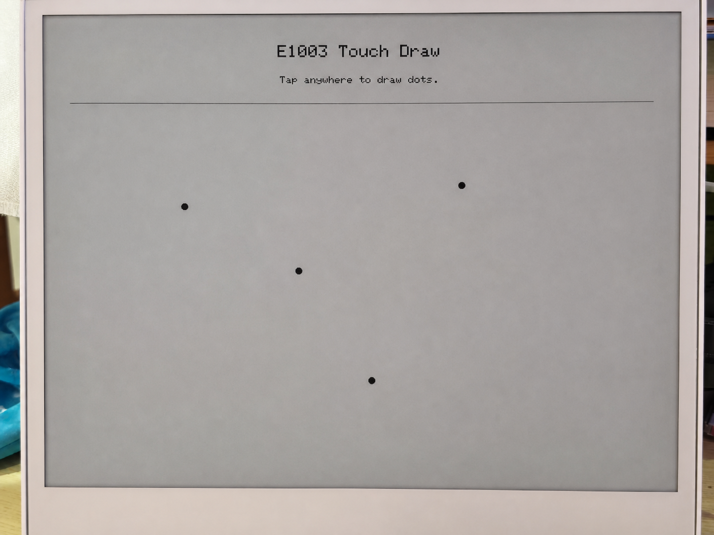
- Draw the startup screen — displays "E1003 Touch Draw" and a prompt on the ePaper.
Touch polling loop (loop()):
- Poll every 30 ms — reads the GT911 status register to check if a new touch event is available.
- Read touch coordinates — extracts the raw X/Y from the GT911 point data registers, then maps them to display coordinates using
mapTouchToDisplay()(which accounts for any difference between touch resolution and display resolution). - Debounce and distance check — a new dot is only drawn if:
- At least 450 ms have passed since the last draw, or
- The touch point has moved at least 12 pixels from the last drawn point.
- Draw on the ePaper —
fillCircle()draws a solid black dot,drawCircle()adds a gray halo ring, thenupdate()pushes the frame buffer to the ePaper panel.
Each update() call triggers a full ePaper refresh, which takes about 1–2 seconds on the E1003 panel. This is normal — ePaper is not a fast-refresh display. The debounce logic (DRAW_MIN_MS = 450 ms) is designed to avoid overwhelming the panel with refresh requests.
Prerequisites
Before running this sketch:
- Install the Seeed_GFX library via Arduino Library Manager.
- Set PSRAM to OPI PSRAM in the Tools menu — without PSRAM, the display buffer cannot be allocated and
display_.width()will return 0. - Set Flash Size to 8 MB.
- Select the XIAO_ESP32S3 board.
Expected Output
========================================
  E1003_TouchDraw - reTerminal E1003
========================================
[display] PSRAM found: yes, free PSRAM: 8159232 bytes
[display] Ready: 1872 x 1404
[touch] GT9xx found at 0x5D, product: 911
[touch] Touch range: 1872 x 1404, display: 1872 x 1404
[touch] Ready.
After tapping the screen:
[touch] raw=(468,302) screen=(468,302)
[touch] raw=(920,756) screen=(920,756)
[touch] raw=(1400,1100) screen=(1400,1100)
Troubleshooting
Q1: Serial output is still visible in deep sleep — does that mean the low-power sketch is not working?
This is normal and does not mean the deep sleep failed.
The serial output you see is handled by the carrier board's USB-UART bridge chip (not the ESP32-S3 itself). The bridge chip is powered directly from the USB connection, so it stays active regardless of whether the ESP32-S3 is awake or asleep. This is actually a deliberate design choice — it ensures you can always see serial output and upload new firmware even if the device enters a rapid deep-sleep cycle.
To confirm deep sleep is truly active, check the serial log:
- If you see
[SLEEP] Entering deep sleep now.followed by silence, the device is in deep sleep. - If you see
[ERROR] deep sleep did not start!, then something went wrong.
Q2: How do I correctly use the RTC sketch for different scenarios?
- First Boot
- Reboot / Repower
- Recalibrate
Scenario: Brand-new board or just replaced the CR1220 battery.
You don't need to change anything — just upload the sketch as-is.
On a brand-new board, the PCF8563's internal VL (Voltage Low) flag is always 1 because the battery has never powered the clock. The sketch reads VL=1 on startup and automatically writes the compile timestamp to the RTC.
Confirm your USER CONFIGURATION looks like this:
#define USE_COMPILE_TIME     // ← enabled ✓
// #define FORCE_SET_TIME   // ← keep commented ✓
→ Click Upload → Done.
Scenario: The board was already running, then rebooted or power-cycled.
You don't need to do anything — just power on.
The CR1220 battery keeps the PCF8563 ticking while the main power is off. On startup, the sketch reads VL=0 (battery healthy) and skips writing, preserving the stored time. The serial output will show the correct time immediately.
Scenario: The RTC time is wrong and needs to be re-calibrated.
Step 1 — Force overwrite. Uncomment FORCE_SET_TIME, then upload:
#define USE_COMPILE_TIME
#define FORCE_SET_TIME      // ← uncomment this line
→ Click Upload → The time is now forced to the compile timestamp.
Step 2 — Disable force overwrite. Immediately comment it back out and upload again:
#define USE_COMPILE_TIME
// #define FORCE_SET_TIME   // ← comment it back out
→ Click Upload → From now on, every reboot preserves the stored time.
Tech Support & Product Discussion
Thank you for choosing our products! We are here to provide you with different support to ensure that your experience with our products is as smooth as possible. We offer several communication channels to cater to different preferences and needs.