Getting Started with reTerminal E Series ePaper Display and EEZ Studio
Introduction
This guide will walk you through designing a professional user interface for the reTerminal E Series using the visual design tool EEZ Studio. You will learn how to create UI elements, generate the necessary code, and finally deploy it to the device using the Arduino IDE. This process allows you to build custom interfaces with excellent visibility and ultra-low power consumption, ideal for HMI applications.
Materials Required
To complete this tutorial, please prepare one of the following reTerminal E Series devices:
| reTerminal E1001 | reTerminal E1002 |
|---|---|
 |  |
What is EEZ Studio?
EEZ Studio is a modern visual programming and UI design environment primarily developed for building user interfaces for test and measurement instruments, embedded devices, and other interactive applications. It combines drag-and-drop GUI design, scripting capabilities, and device integration tools, allowing developers, engineers, and makers to quickly create professional interfaces without starting from scratch.
In short, EEZ Studio acts as a bridge between hardware and software, enabling you to design, prototype, and deploy user experiences more efficiently.
Why use EEZ Studio?
- Visual Interface Design – Create complex UIs with a WYSIWYG editor, reducing the need for manual coding.
- Rapid Prototyping – Quickly test and validate design ideas, saving development time and cost.
- Cross-platform Support – Build applications that can run on multiple operating systems and embedded targets.
- Integration with Hardware – Directly connect and control lab instruments, IoT devices, and custom boards.
- Open Source Ecosystem – Benefit from a community-driven toolset with transparency and flexibility.
With EEZ Studio, you can move from concept to working prototype in a fraction of the time, while ensuring that your designs are both professional and adaptable to future requirements.
Difference with SquareLine Studio
Although EEZ Studio and SquareLine Studio are both GUI design tools, they focus on different goals and user scenarios:
| Aspect | EEZ Studio | SquareLine Studio |
|---|---|---|
| Primary Purpose | Designed for test & measurement instruments, embedded systems, and hardware/software integration | Focused on building GUIs for embedded systems (especially with LVGL) |
| Target Users | Engineers, product developers, makers, lab/test instrument designers | Embedded UI developers, hobbyists, IoT product designers |
| Hardware Integration | Direct integration with instruments, measurement devices, and automation systems | Mostly focused on display/UI generation, not external device integration |
| Open Source | Community-driven, transparent, extensible Premium/paid technical support is available | Closed-source, commercial product with licensing |
| Workflow | Can prototype, simulate, and control real devices from one environment | Primarily generates UI code to be compiled into an embedded project |
Getting Started with EEZ Studio
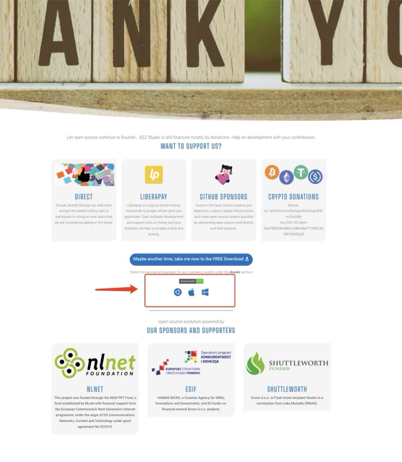
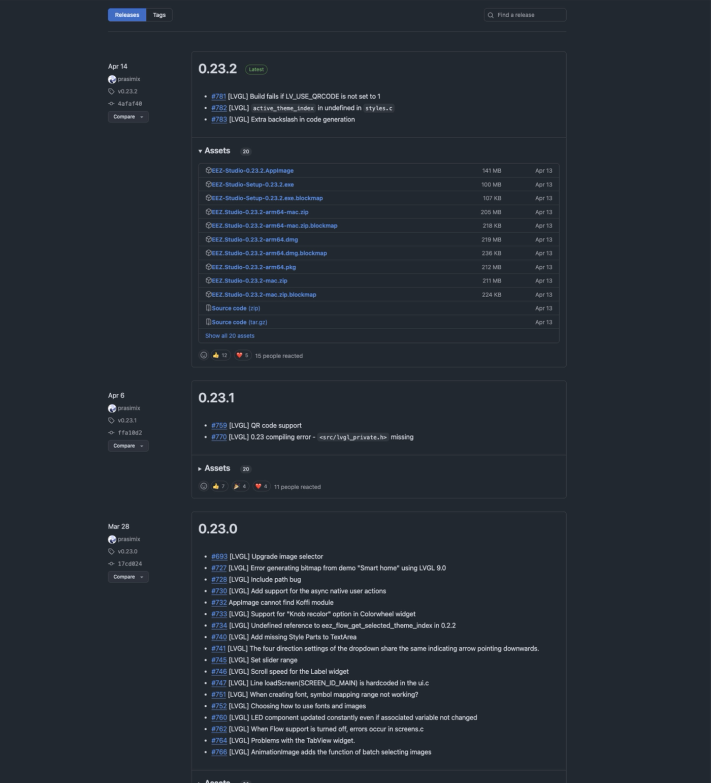
EEZ Studio Installation
EEZ Studio Install Link After accessing the download link, select the system version compatible with your computer to download.
Create Project
Starting a New LVGL Project
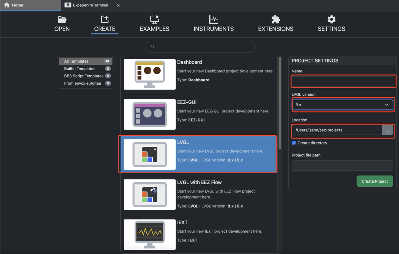
At the top of the EEZ Studio interface, click the “CREATE” button. In the project template list on the left, locate and select the “LVGL” project.
Name:Name your project file,For the sake of convenience in explaining subsequent content in our articles, we will refer to it here as EEZ_UI.LVGL Version:Specifies the LVGL library version used by the project.Select 9.x from the dropdown menu.Location:Specify the storage path for project files on your computer.The default path typically points to a default project folder within your EEZ Studio download or installation directory (e.g., C:\Users\YourUser\Documents\EEZ Studio\Projects or a similar path).If you need to change the storage location, click the folder icon (or ellipsis ...) to the right of the Location text box.
Project Settings Configuration
When building your LVGL UI project for the E-paper reTerminal, you need to configure the EEZ Studio Project Settings properly to ensure that the generated UI files are compatible with your Arduino or embedded environment.
Step 1. Open Project Settings
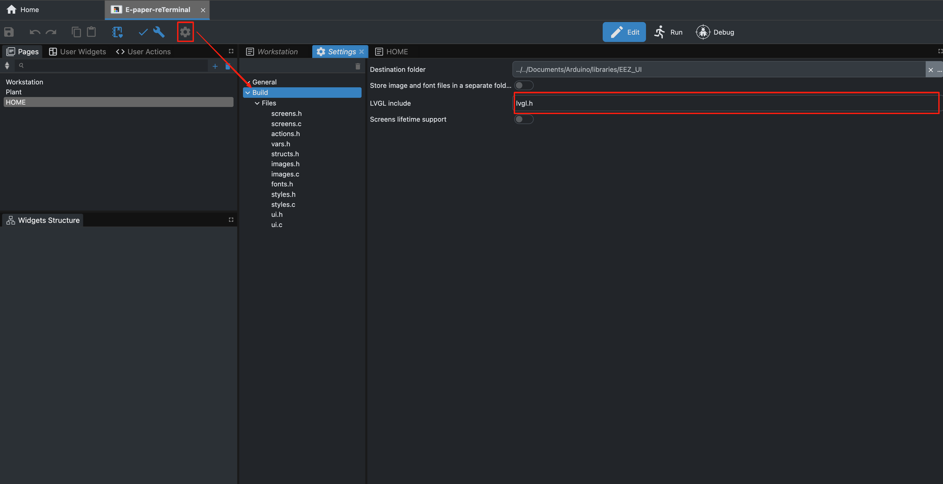
Click the ⚙️ (Settings) icon on the top toolbar, as shown below. This will open the Project Settings panel on the right side of the workspace.
Step 2. Configure Build Output and LVGL Include
Under General → Build, locate the following fields:
- LVGL include: Input lvgl.h to include the correct LVGL header during compilation.
💡 This ensures the generated UI code can correctly reference the LVGL library during build.
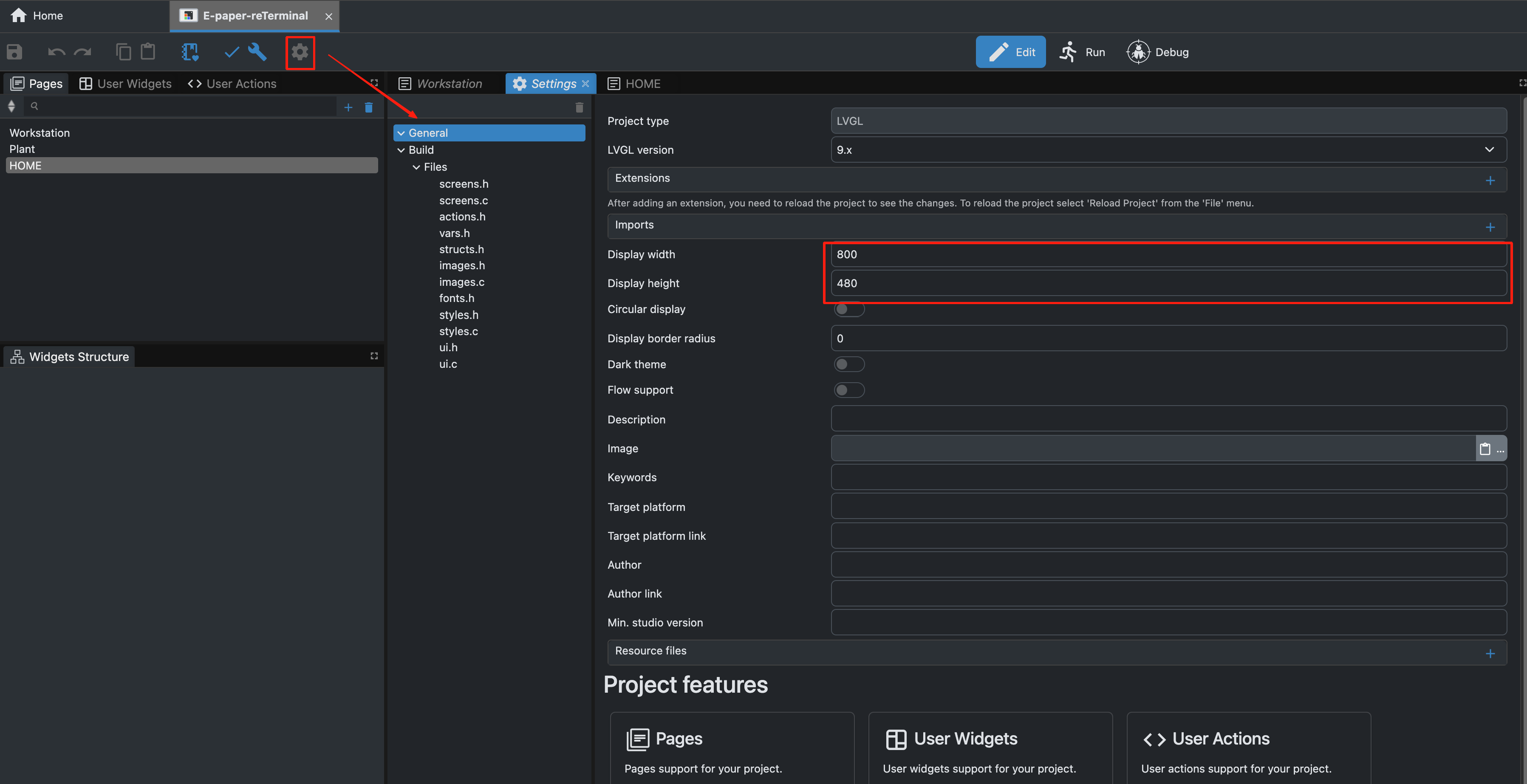
Step 3. Set Display Resolution
Next, still under Settings → General, configure your display’s resolution:
- Display width: 800
- Display height: 480
🧩 These parameters define the target E-paper screen resolution for the UI layout and coordinate mapping. Make sure the values match your specific E-paper model (for example, 7.5-inch E-paper – 800×480).
Project Parameter Settings & UI Interface Design
UI Interface Design
UI (User Interface) design is crucial in embedded product development, as it directly determines the user experience. An aesthetically pleasing, intuitive, and responsive interface not only enhances the product's usability but also boosts its overall appeal.
In EEZ Studio, you can rapidly assemble interfaces by dragging and dropping components. Utilize tools like Styles, Fonts, Bitmaps, and Themes to precisely control visual effects, crafting a professional and distinctive user experience.
Below is an introduction to the recommended tools:
Introduction to the Rightmost Component
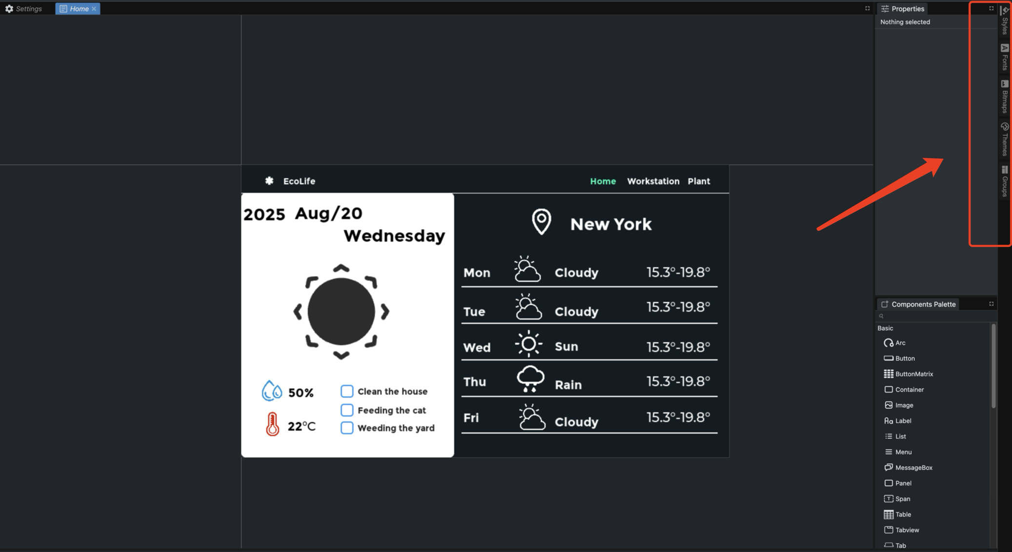
- Styles: Visual attributes used to unify and reuse interface elements, ensuring consistency and efficient maintenance.
- Bitmap: Commonly used for backgrounds, icons, logos, etc., to enhance visual presentation.
- Fonts: Ensure clear text readability while supporting multilingual content and brand styling.
- Themes: Define overall interface aesthetics, enabling quick toggles like light/dark mode.
- Groups: Organize multiple widgets together for unified management and layout.
In this tutorial, I'll guide you through designing the UI for a website or app's homepage. Once you master the core techniques, you'll be able to apply them to create any interface you desire with ease.
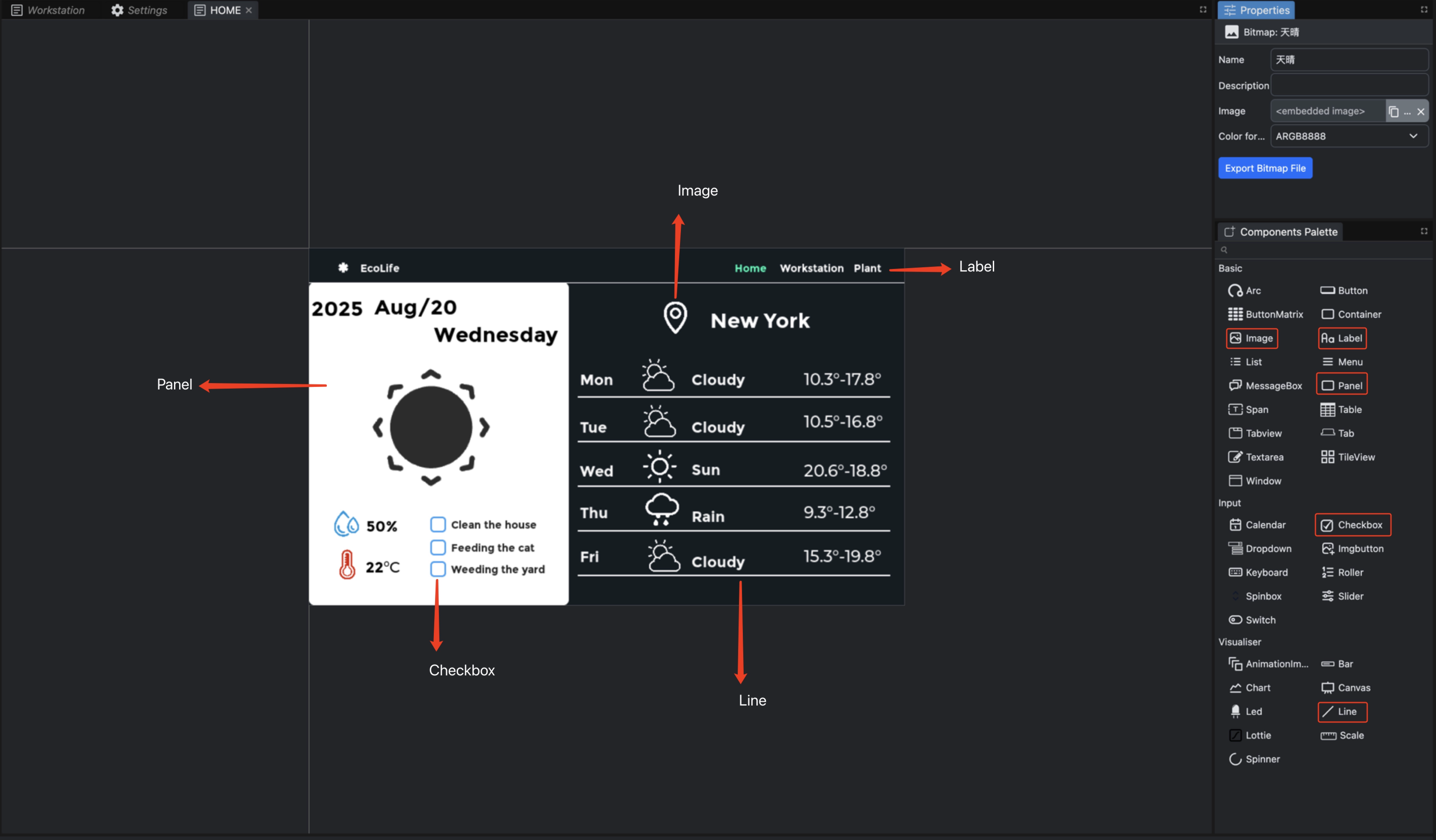
This page is composed of five components:
- Panel
- Label
- Line
- Checkbox
- Image
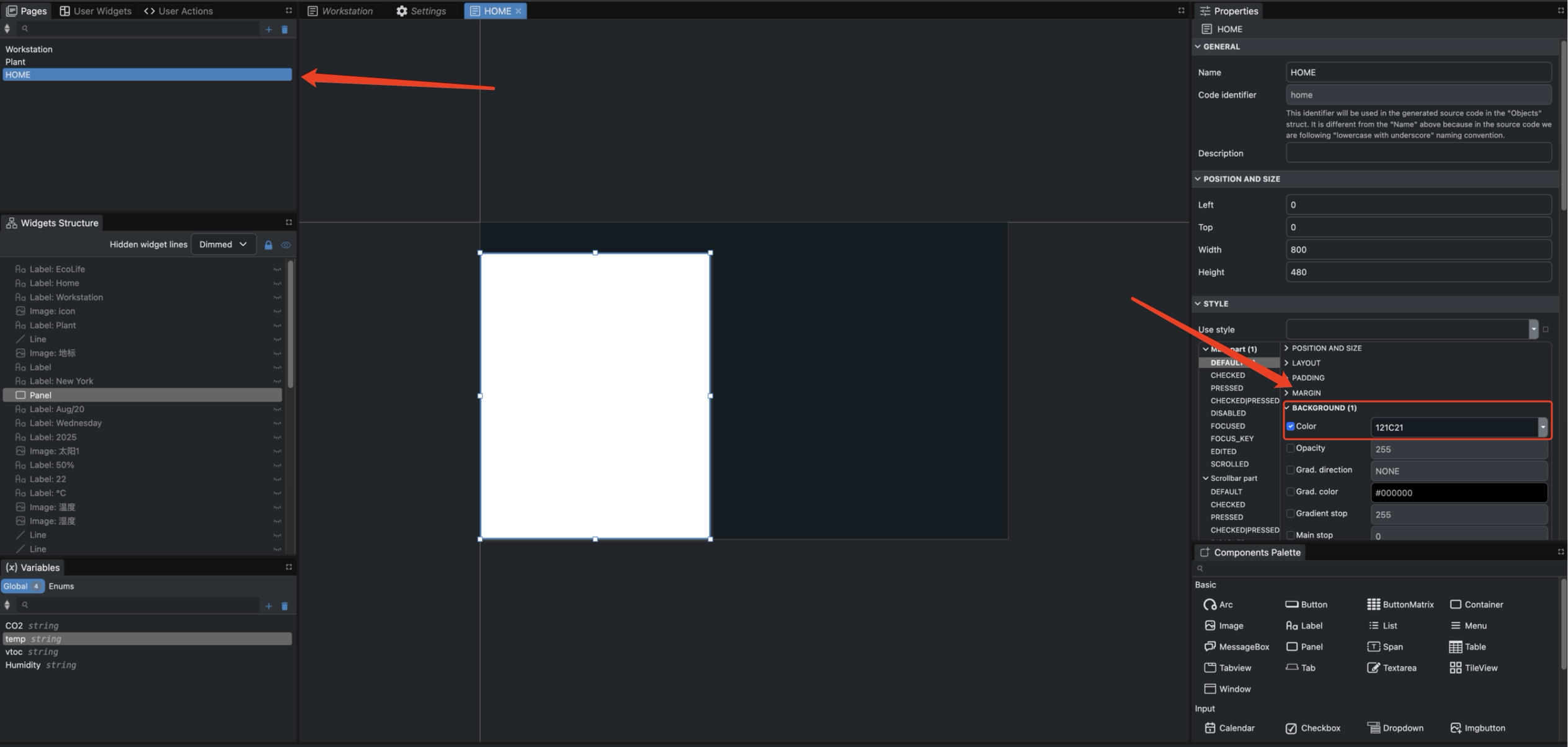
Step 1 .Change the background color of the canvas
- Select the canvas whose background color you need to change.
- Check Color, then select your preferred hexadecimal color code.
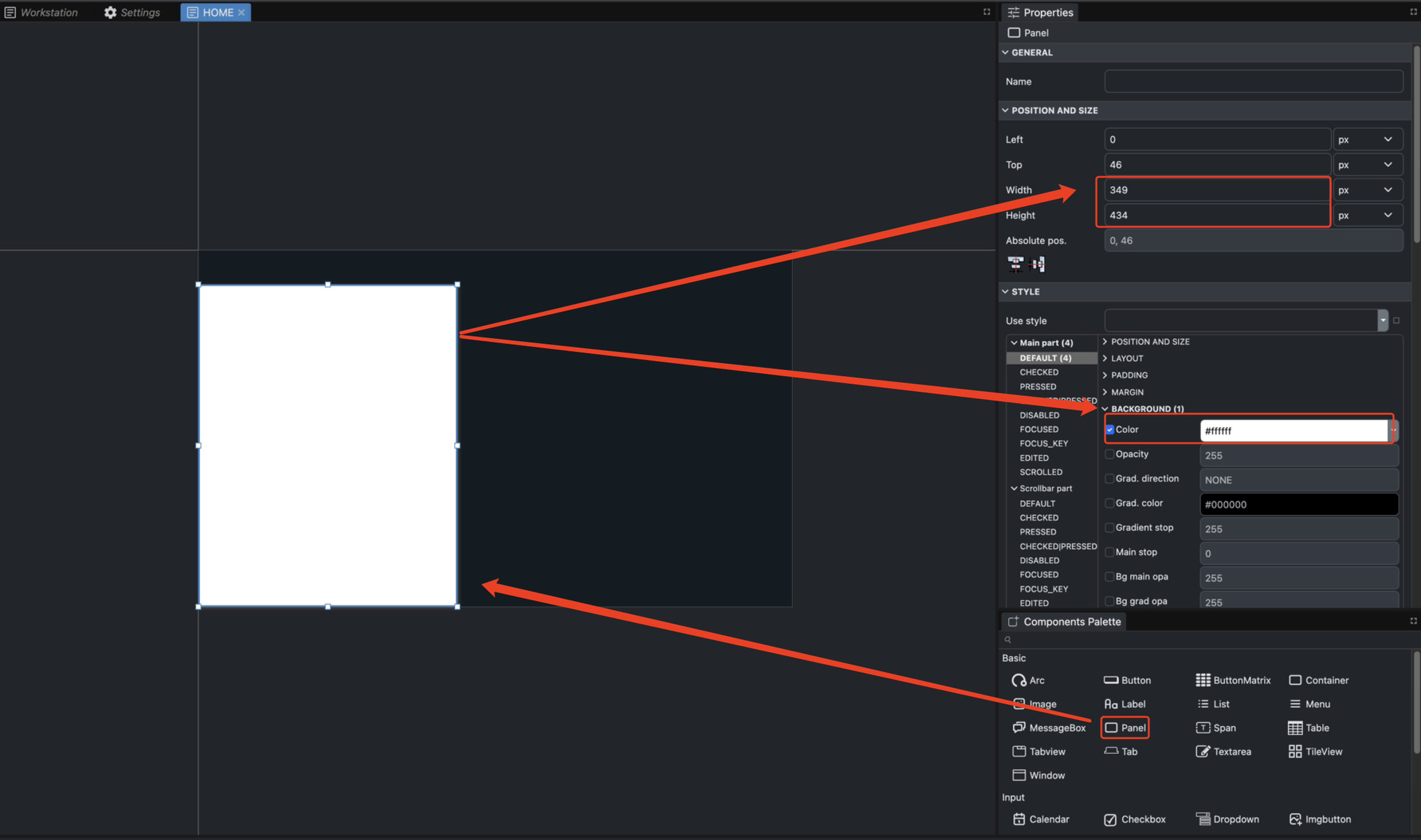
Step 2 .Add Panel
-
Drag the Panel component from the Basic section onto the canvas and adjust its Width and Height.
-
Check Color, then select your preferred hexadecimal color code.
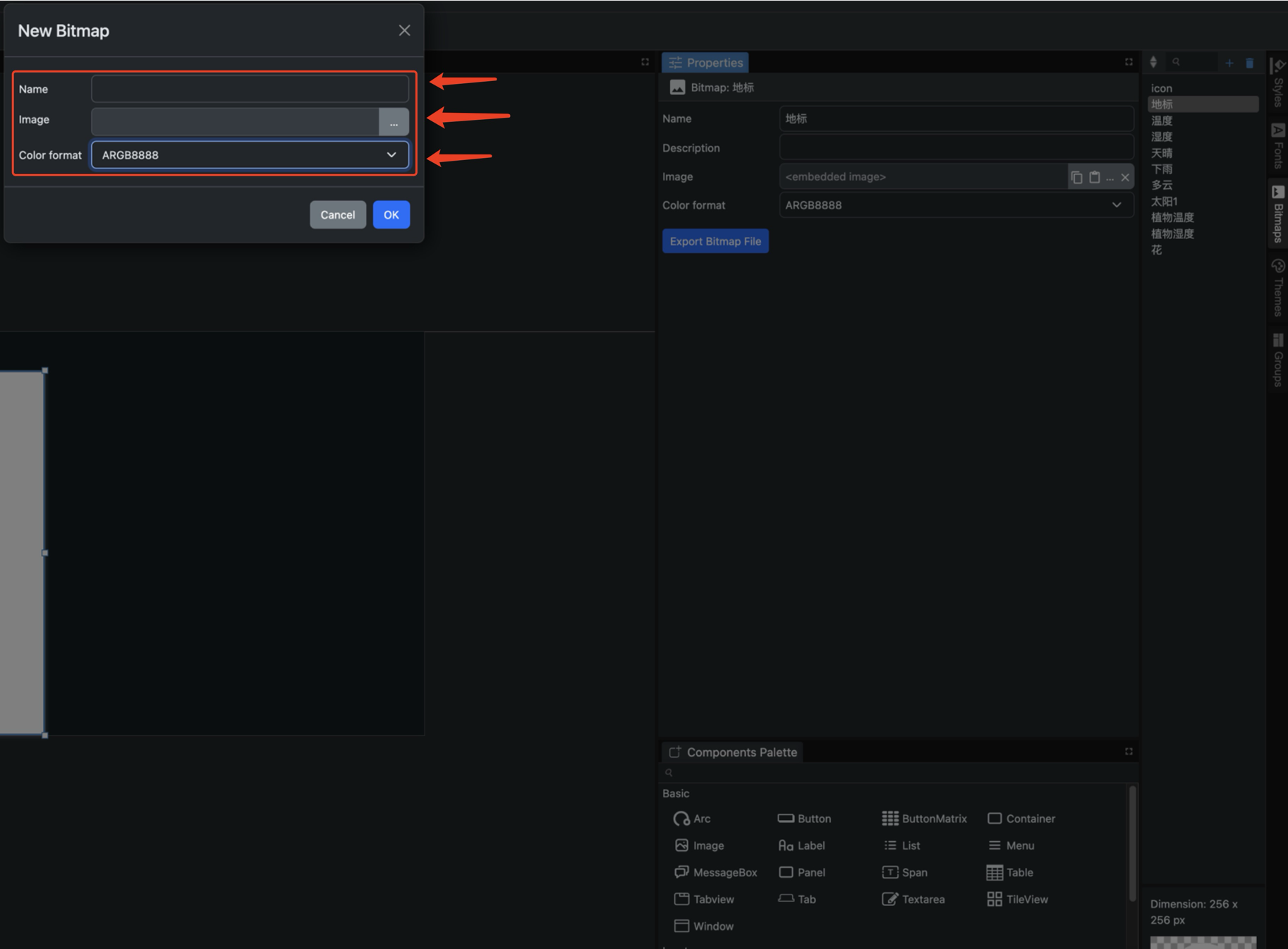
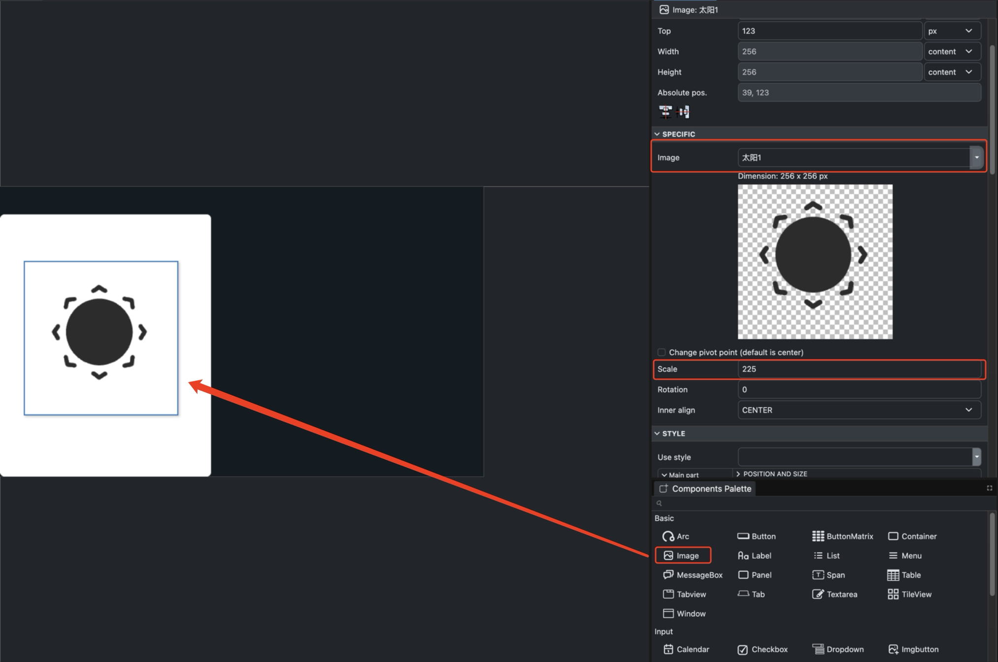
Step 3 .Add Bitmaps
- Click the Bitmaps icon in the far-right sidebar to add an image.
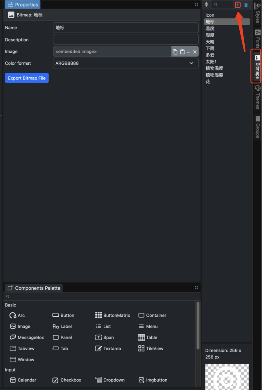
- Name the images you select; you will need to choose images based on your naming convention later.
- Drag the Image component from the Basic group onto the canvas, then select your image and set the size using Scale.
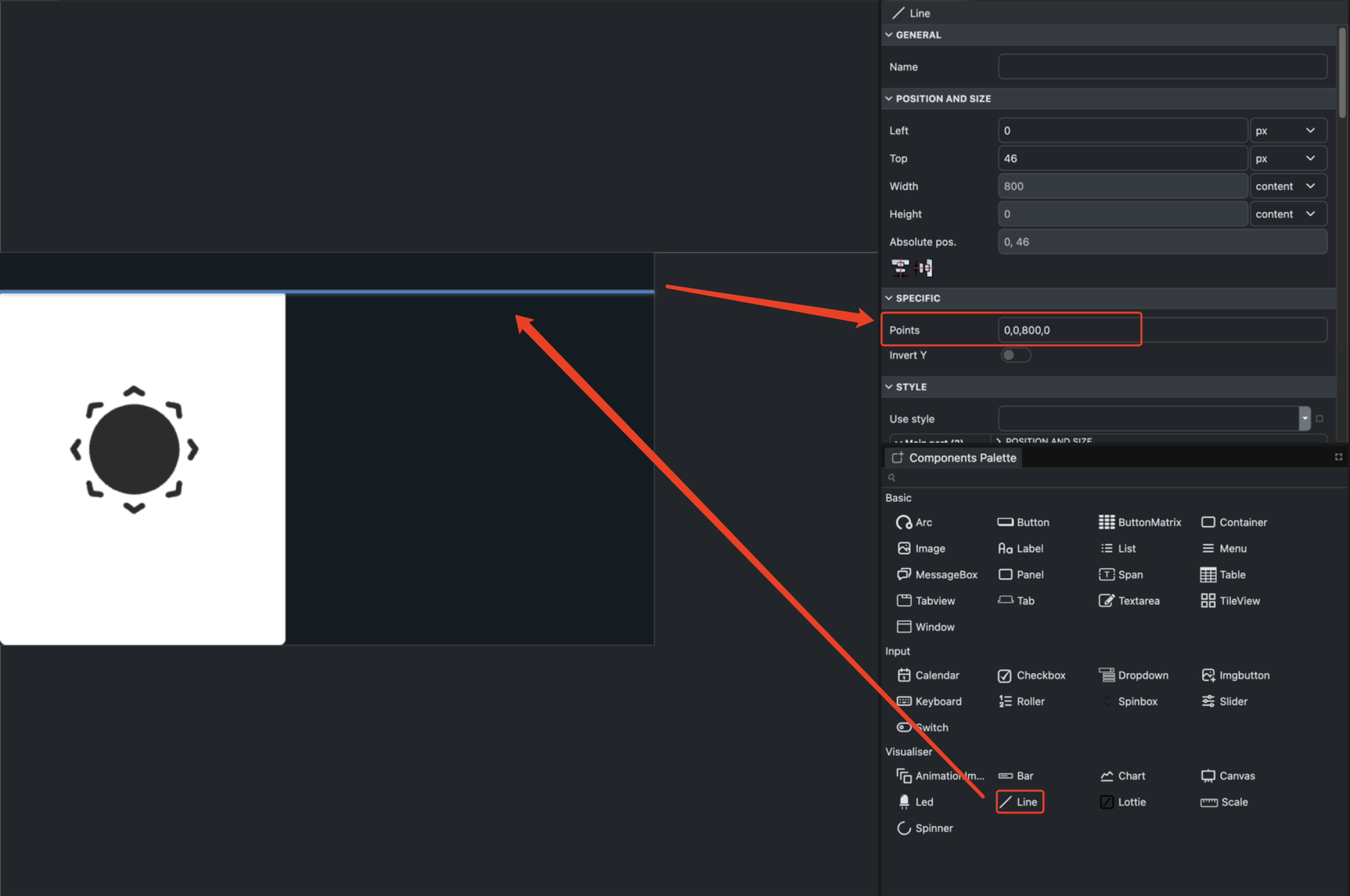
Step 4 .Add Line
- Drag the Line component from the Visualiser group onto the canvas. Set the start and end points of the Points to determine the line's length and height.
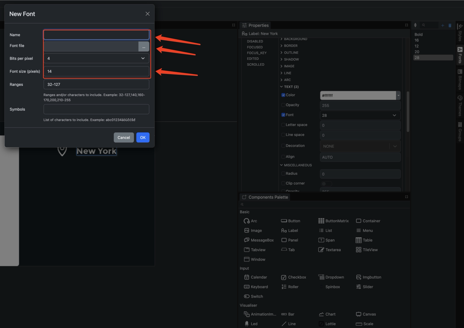
Step 5 .Add Label
- Drag the Label component from the Basic group onto the canvas, then select your font color and font format settings.
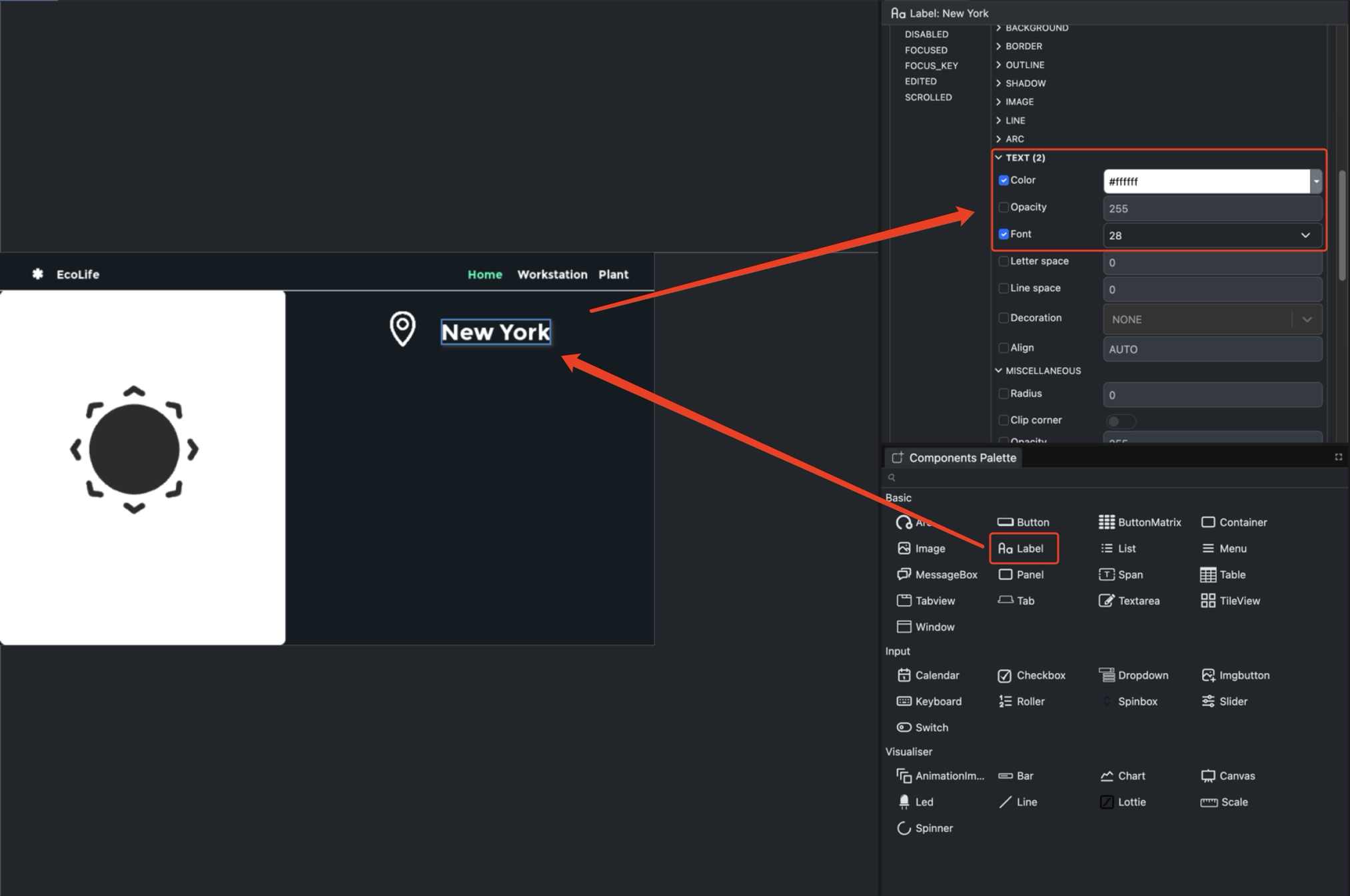
- Click the Fonts box in the rightmost column to add your font formats.
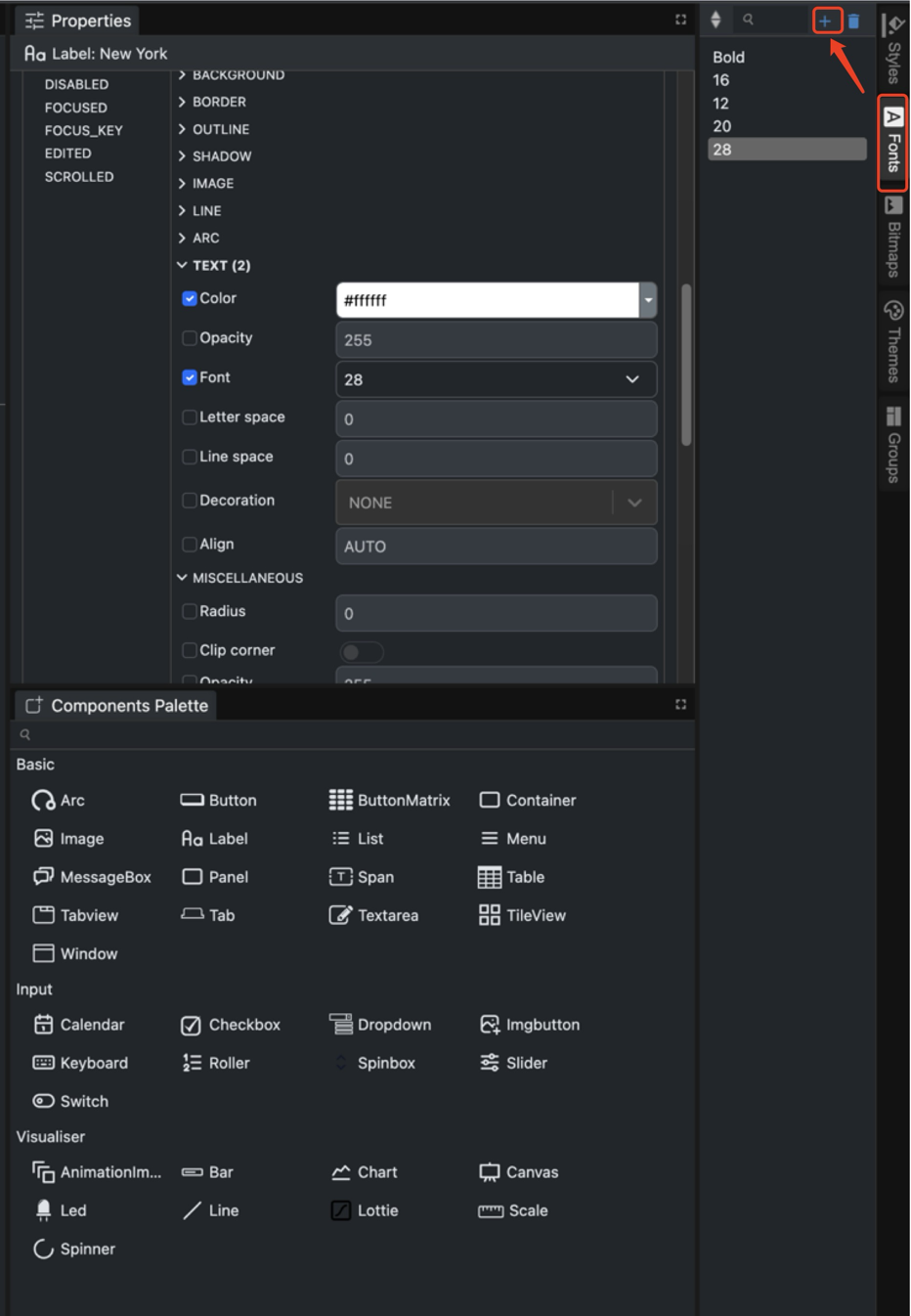
- Set the font name and size
The above outlines the basic usage of these five components. You can arrange them according to the reference diagram or your own designed UI interface.
Code Generation and Deployment
After completing the UI design, you need to save the project and preview it in the simulator. Once verified, execute the build operation to generate code files executable on the target hardware.
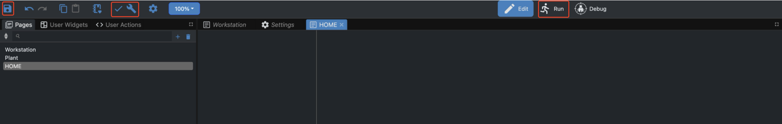
Step 1 .Save Project
Click the Save icon (floppy disk shape, located next to the “OPEN” button) at the top of the interface to save your project.
Step 2 .Preview Design
Click the Run icon (play button) in the toolbar to launch the simulator and interactively preview the UI effects.
Step 3 .Build Project
Click the Compile icon (checkmark button) to check for syntax or logic errors in the project. Click the Build icon (wrench button) to generate files such as UI code, image data, and font data.
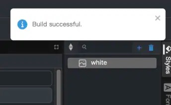
Step 4 .Confirming Successful Build
Upon completion, EEZ Studio displays a green prompt stating “Build successful,” indicating the code has been generated successfully.
Environmental Preparation
To program reTerminal E Series ePaper Display with Arduino, you'll need to set up the Arduino IDE with ESP32 support.
If this is your first time using Arduino, we highly recommend you to refer to Getting Started with Arduino.
Arduino IDE Setup
Step 1. Download and install the Arduino IDE and launch the Arduino application.
Step 2. Add ESP32 board support to Arduino IDE.
In Arduino IDE, go to File > Preferences and add the following URL to the "Additional Boards Manager URLs" field:
https://raw.githubusercontent.com/espressif/arduino-esp32/gh-pages/package_esp32_index.json
Step 3. Install ESP32 board package.
Navigate to Tools > Board > Boards Manager, search for "esp32" and install the ESP32 package by Espressif Systems.
Step 4. Select the correct board.
Go to Tools > Board > ESP32 Arduino and select XIAO_ESP32S3.
Step 5. Connect your reTerminal E Series ePaper Display to your computer using a USB-C cable.
Step 6. Select the correct port from Tools > Port.
ePaper Display Programming
The reTerminal E1001 features a 7.5-inch black and white ePaper display, while the reTerminal E1002 is equipped with a 7.3-inch full color ePaper display. Both displays provide excellent visibility in various lighting conditions with ultra-low power consumption, making them ideal for industrial applications that require always-on displays with minimal power usage.
Using the Seeed_GFX Library
To control the ePaper display, we'll use the Seeed_GFX library, which provides comprehensive support for various Seeed Studio display devices.
Step 1. Download the Seeed_GFX library from GitHub:
Step 2. Install the library by adding the ZIP file in Arduino IDE. Go to Sketch > Include Library > Add .ZIP Library and select the downloaded ZIP file.
If you have previously installed the TFT_eSPI library, you may need to temporarily remove or rename it from your Arduino libraries folder to avoid conflicts, as Seeed_GFX is a fork of TFT_eSPI with additional features for Seeed Studio displays.
- Programming reTerminal E1001
- Programming reTerminal E1002
Programming reTerminal E1001 (7.5-inch Black & White ePaper)
Let's explore a simple example that demonstrates basic drawing operations on the black and white ePaper display.
Step 1. Open the example sketch from the Seeed_GFX library: File > Examples > Seeed_GFX > ePaper > Basic > HelloWorld
Step 2. Create a new file named driver.h in the same folder as your sketch. You can do this by clicking the arrow button in the Arduino IDE and selecting "New Tab", then naming it driver.h.

Step 3. Go to the Seeed GFX Configuration Tool and select reTerminal E1001 from the device list.

Step 4. Copy the generated configuration code and paste it into the driver.h file. The code should look like this:
#define BOARD_SCREEN_COMBO 520 // reTerminal E1001 (UC8179)
Programming reTerminal E1002 (7.3-inch Full Color ePaper)
The full color ePaper display supports red, black, and white colors, allowing for more visually rich interfaces.
Step 1. Open the color example sketch from the Seeed_GFX library: File > Examples > Seeed_GFX > ePaper > Colorful > HelloWorld
Step 2. Create a new file named driver.h in the same folder as your sketch, following the same process as before.

Step 3. Go to the Seeed GFX Configuration Tool and select reTerminal E1002 from the device list.

Step 4. Copy the generated configuration code and paste it into the driver.h file. The code should look like this:
#define BOARD_SCREEN_COMBO 521 // reTerminal E1002 (UC8179C)
Deploying the EEZ Studio Project to Arduino
First, locate OPI PSRAM in the ‘Tools’ menu bar and open it.

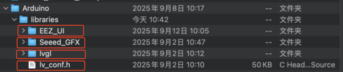
These two underlying driver files need to be added to our project directory.

Port the following project files (including four files) to the Arduino Library for use in Arduino projects.
The EEZ_UI file is generated during the build process in EEZStudio. You need to locate the path where you saved it.
- 🔗 [ZIP] Code
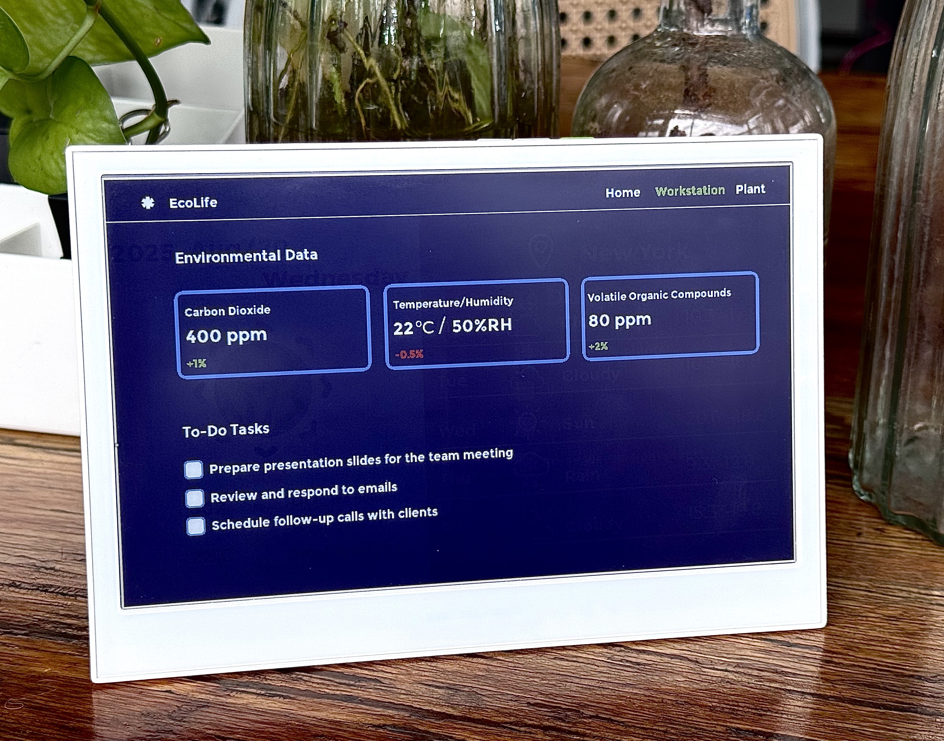
Here is the main Arduino sketch to run the UI: Three buttons correspond to three different screens, starting with green: HOME\Workstation\Plant in sequence.
#include <TFT_eSPI.h>
#include <lvgl.h>
#include <ui.h>
#include "e1002_display.h"

const int BUTTON_KEY0 = 3;
const int BUTTON_KEY1 = 4;
const int BUTTON_KEY2 = 5;

int32_t page_index;

bool lastKey0State = HIGH;
bool lastKey1State = HIGH;
bool lastKey2State = HIGH;

e1002_driver_t e1002_driver;

void setup()
{
    String LVGL_Arduino = "Automotive Dashboard Demo - LVGL ";
    LVGL_Arduino += String('V') + lv_version_major() + "." + lv_version_minor() +
                    "." + lv_version_patch();
    Serial.begin(115200);
    Serial.println(LVGL_Arduino);
    Serial.println("Initializing 6-color e-paper display...");
    e1002_display_init(&e1002_driver);

    pinMode(BUTTON_KEY0, INPUT_PULLUP);
    pinMode(BUTTON_KEY1, INPUT_PULLUP);
    pinMode(BUTTON_KEY2, INPUT_PULLUP);

    lastKey0State = digitalRead(BUTTON_KEY0);
    lastKey1State = digitalRead(BUTTON_KEY1);
    lastKey2State = digitalRead(BUTTON_KEY2);

    ui_init();
    page_index = SCREEN_ID_HOME;
    loadScreen((ScreensEnum)page_index);
    Serial.println("Boot: Main Screen");
}

void loop()
{
    lv_timer_handler();
    ui_tick();
    delay(50);

    bool currentKey0State = digitalRead(BUTTON_KEY0);
    bool currentKey1State = digitalRead(BUTTON_KEY1);
    bool currentKey2State = digitalRead(BUTTON_KEY2);

    if (lastKey0State == HIGH && currentKey0State == LOW) {
        page_index = SCREEN_ID_HOME;
        loadScreen((ScreensEnum)page_index);
        Serial.println("Switched to Main Screen");
        delay(50);
    }

    if (lastKey1State == HIGH && currentKey1State == LOW) {
        page_index = SCREEN_ID_WORKSTATION;
        loadScreen((ScreensEnum)page_index);
        Serial.println("Switched to Plant Screen");
        delay(50);
    }

    if (lastKey2State == HIGH && currentKey2State == LOW) {
        page_index = SCREEN_ID_PLANT;
        loadScreen((ScreensEnum)page_index);
        Serial.println("Switched to Setting Screen");
        delay(50);
    }

    lastKey0State = currentKey0State;
    lastKey1State = currentKey1State;
    lastKey2State = currentKey2State;

    if (e1002_display_should_refresh(&e1002_driver))
    {
        Serial.println("Refreshing e-paper display...");
        e1002_display_refresh(&e1002_driver);
        Serial.println("Display refresh complete");
    }

    delay(10);
}
-
e1002_display_init():Initializes the e-ink display hardware and sets its operating parameters. -
pinMode(..., INPUT_PULLUP):Configures the button pin as an input mode and enables the internal pull-up resistor. This ensures the pin remains at a high level (HIGH) when the button is not pressed and connects to ground, becoming low (LOW), when pressed. -
ui_init()andloadScreen():These functions initialize the LVGL user interface library and load the specified screen -
lv_timer_handler():This is an essential function in the LVGL library that handles timer events within LVGL, such as animations and screen updates. -
if (lastKey0State == HIGH && currentKey0State == LOW):This line is the core of key event detection. It checks whether a key state has changed from unpressed to pressed. -
When the condition is met, the program updates
page_indexand calls theloadScreen()function to load a new page. -
State Update:
lastKey0State = currentKey0State;This line is crucial. It saves the current key state for use in the nextloop()iteration, enabling the next state comparison. -
E-ink Refresh:
e1002_display_should_refresh()ande1002_display_refresh()manage the E-ink screen refresh. Unlike LCD screens, E-ink cannot refresh in real-time. It typically requires selective or full-screen refreshes at specific intervals to conserve power and extend lifespan. This code implements that on-demand refresh mechanism. -
delay(10): This is a simple software debouncing measure to prevent the program from misinterpreting physical key wobble as multiple presses.
Interface Display Diagram
| Home Page | Workstation Page | Photo Page |
|---|---|---|
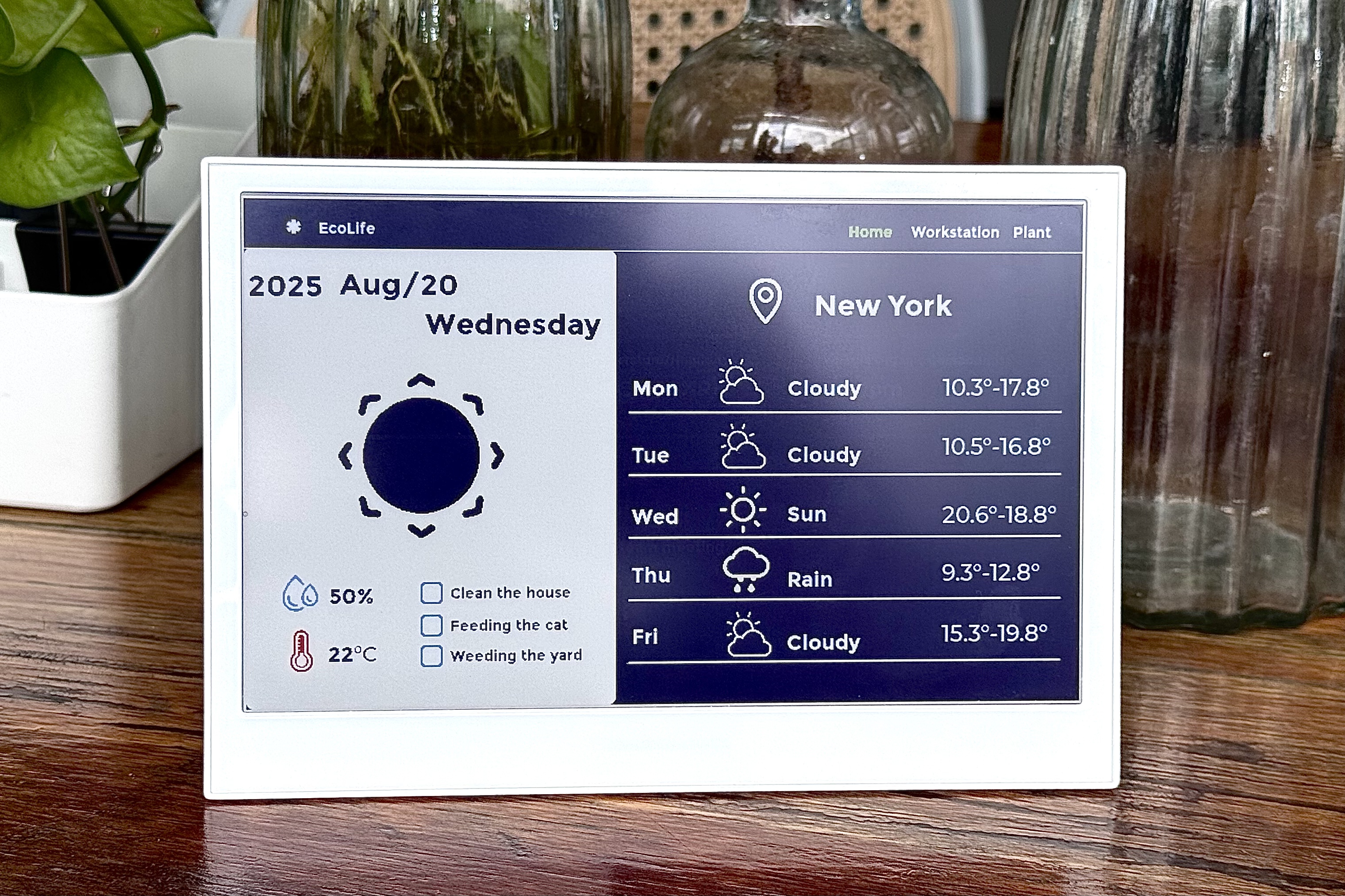 | | 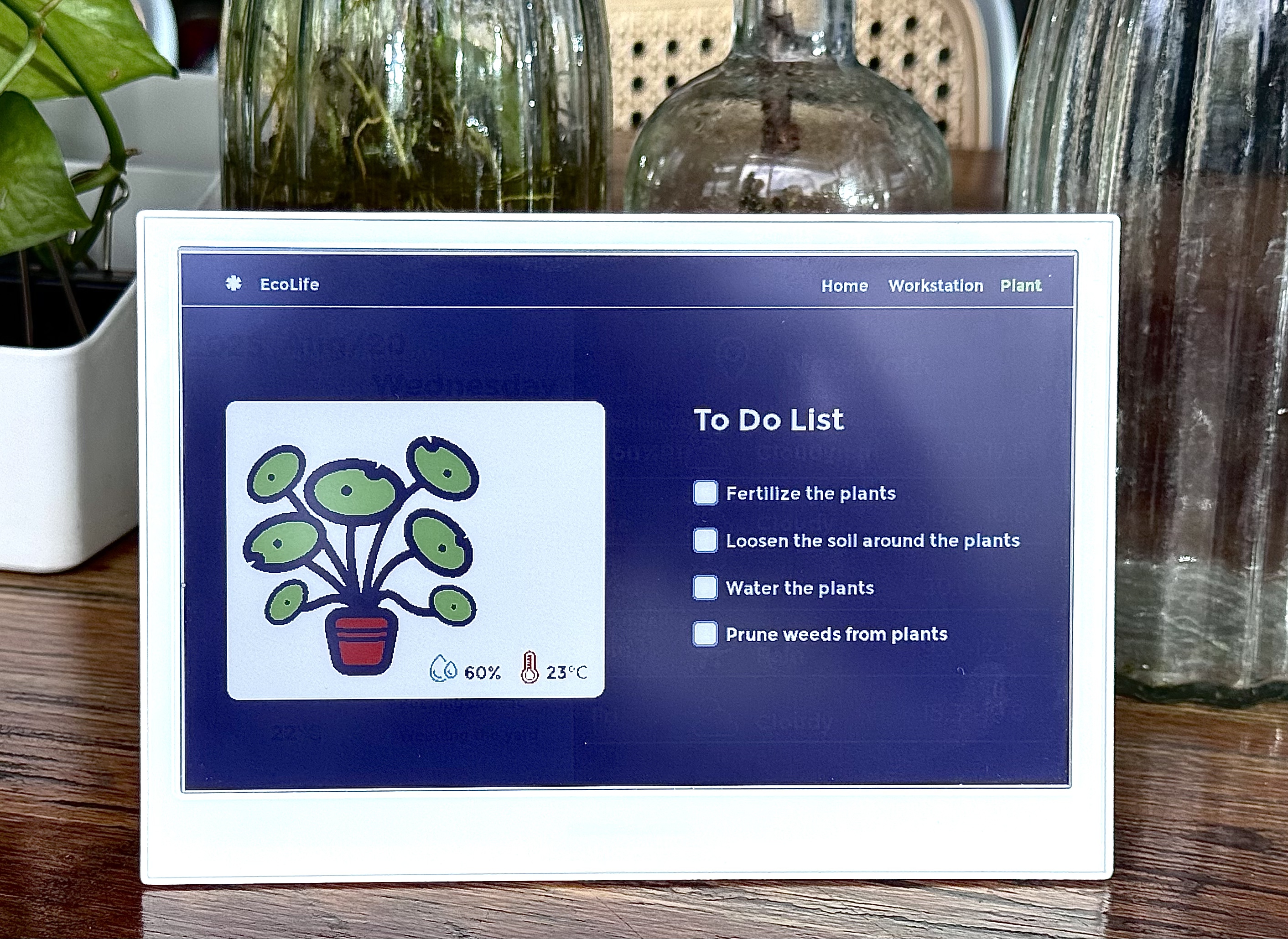 |
Tech Support & Product Discussion
Thank you for choosing our products! We are here to provide you with different support to ensure that your experience with our products is as smooth as possible. We offer several communication channels to cater to different preferences and needs.